

Page 1

EN | FR | DE | ES | IT | NL
ADVIZOR | METRON
INSTRUCTION MANUAL
www.suunto.com
Page 2
1. 2.
4.3.
8.7.6.5.
10.9.
12.11.
Page 3
13. 14.
16.15.
20.19.18.17.
22.21.
24.23.
Page 4
25. 26.
28.27.
32.31.30.29.
34.33.
36.35.
Page 5
37. 38.
40.39.
42.41.
46.45.
44.43.
48.47.
Page 6
49.
50.
52.51.
54.53.
58.57.
55.
59. 60.
56.
Page 7
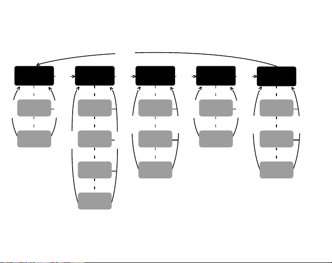
[MODE]
[MODE] [MODE] [MODE] [MODE]
TIME BAROMETERALTIMETER
[SELECT]
> >
DAILY
[SELECT]
ALARMS
[SELECT]
[MODE]
DUAL TIME
[SELECT]
>
DIFFERENCE
MEASUREMENT
[SELECT]
>
24 HOUR
MEMORY
[SELECT]
[SELECT]
>
LOGBOOK
[SELECT]
>
LOGBOOK
HISTORY
[MODE]
[SELECT]
>
DIFFERENCE
MEASUREMENT
[SELECT]
>
[SELECT]
4 DAY
MEMORY
[SELECT]
>
SEA LEVEL
PRESSURE
[MODE]
COMPASS
[SELECT]
DECLINATION
ADJUSTMENT
[SELECT]
[SELECT]
COMPASS
CALIBRATION
HEART RATE
MONITOR
[MODE]
[SELECT]
STOPWATCH
[SELECT]
[SELECT]
INTERVAL
TIMER
[SELECT]
>
>
[MODE]
>
>
>
MEMORY
Page 8

INSTRUCTION MANUAL
Customer SERVICE Contacts
Suunto USA
Phone 1 (800) 543-9124
Suunto Canada
Phone 1 (800) 776-7770
Web Site
Suunto Europe
Phone +33 3 90 20 74 30
Fax +33 3 90 20 74 40
Web Site
Suunto Oy
Phone +358 9 875 870
Fax +358 9 8758 7301
Web Site
Congratulations, your newly purchased Wristop Computer is designed to provide years of enjoyment in whatever
outdoor activities you undertake.
Along with this product you will find a Warranty card (only in USA and Canada), this Users Guide, and a full
service support team ready to assist you anytime, anywhere, quickly and professionally.
We wish you many unforgettable moments with your new Wristop Computer!
www.suuntousa.com
www.suuntoeurope.com
www.suunto.com
1
EN
Page 9

TABLE OF CONTENTS
CHAPTER 1 INTRODUCTION ........................................................... 6
1.1 GENERAL INFORMATION ............................................................................................ 6
1.2 MAIN FUNCTIONS (MODES) ........................................................................................ 6
1.2.1 Water Resistance ............................................................................................ 6
1.2.2 Backlight Features ........................................................................................... 7
1.3 BUTTON FUNCTIONS ................................................................................................... 7
1.3.1 The [Mode] Button ........................................................................................... 7
1.3.2 The [+] Button .................................................................................................. 7
1.3.3 The [-] Button ................................................................................................... 7
1.3.4.The [Select] Button .......................................................................................... 8
1.4 LCD DISPLAY .................................................................................................................8
1.5 MEASUREMENTS AND UNITS .................................................................................... 9
1.5.1 Selecting the Units of Measurement ............................................................. 10
1.6 PRESSURE SENSOR CALIBRATION ........................................................................ 11
1.7 CARE AND MAINTENANCE ........................................................................................ 11
1.8 SERVICE ...................................................................................................................... 11
1.8.1 Battery Replacement of the Wristop Computer ............................................ 12
1.8.2 Battery Replacement of the transmitter belt ................................................. 13
CHAPTER 2 HEART RATE MONITOR ............................................ 13
2.1 SUUNTO WRISTOP COMPUTER AND TRANSMITTER IN A WATER
ENVIRONMENT ........................................................................................................ 13
2.2 SUUNTO WRISTOP COMPUTER AND INTERFERENCE ........................................ 14
2.3 WARNINGS .................................................................................................................. 1 4
2.4 CARE ............................................................................................................................ 15
2.5 ACTIVATING THE HEART RATE MONITOR .............................................................. 15
2
Page 10

2.6 OPERATION ................................................................................................................. 16
2.6.1 How to Set the Target Zones of the Heart Rate Monitor .............................. 17
2.7 STOPWATCH SUB MODE .......................................................................................... 18
2.7.1 How to Use the Stopwatch ............................................................................ 18
2.8 INTERVAL COUNTDOWN TIMER SUB MODE .......................................................... 20
2.8.1 How to Set the Countdown Timer ................................................................. 20
2.8.2 How to Start the Countdown Timer ............................................................... 21
2.9 HRM MEMORY ............................................................................................................ 22
CHAPTER 3 TIME MODE ................................................................ 24
3.1 HOW TO SET THE TIME ............................................................................................. 25
3.2 DAILY ALARM SUB MODE .......................................................................................... 26
3.2.1 How to Set the Daily Alarms .......................................................................... 26
3.3 DUAL TIME SUB MODE .............................................................................................. 27
3.3.1 Setting the Dual Time Function ..................................................................... 27
CHAPTER 4 ALTIMETER MODE ..................................................... 28
4.1 SETTING THE ALTIMETER ......................................................................................... 30
4.2 ALTITUDE DIFFERENCE MEASUREMENT SUB MODE .......................................... 32
4.2.1 How to Start the Altitude Difference Measurement ....................................... 32
4.3 24-HOUR MEMORY SUB MODE ................................................................................ 33
4.4 LOGBOOK SUB MODE ............................................................................................... 33
4.4.1 Closer examination of the logbook ................................................................ 35
4.4.2 How to Start and Stop a Logbook ................................................................. 36
4.5 LOGBOOK HISTORY SUB MODE .............................................................................. 36
4.5.1 Clearing the Logbook History ........................................................................ 37
CHAPTER 5 BAROMETER MODE ................................................... 37
5.1 PRESSURE DIFFERENCE MEASUREMENT SUB MODE ....................................... 38
3
Page 11

5.1.1 How to Start the Pressure Difference Measurement .................................... 39
5.2 4-DAY MEMORY SUB MODE ...................................................................................... 39
5.3 SEA LEVEL PRESSURE SUB MODE ......................................................................... 40
5.3.1 Setting the Sea Level Pressure .................................................................... 40
5.4 BAROMETRIC TREND INDICATOR ........................................................................... 41
CHAPTER 6 COMPASS MODE ........................................................ 42
6.1 BEARING TRACKING SUB MODE ............................................................................. 43
6.2 DECLINATION ADJUSTMENT SUB MODE ............................................................... 43
6.2.1 Setting the Local Declination ......................................................................... 44
6.3. CALIBRATING THE COMPASS ................................................................................. 44
CHAPTER 7 FREQUENTLY ASKED QUESTIONS ........................... 45
7.1 GENERAL .....................................................................................................................45
7.1.1 Is the Wristop Computer waterproof? ........................................................... 45
7.1.2 How long will the battery last? ....................................................................... 45
7.1.3 What do the segments on the circumference mean? ................................... 46
7.1.4 Why do the segments on the circumference go to the left
(counterclockwise)? ....................................................................................... 46
7.1.5 Why are there two symbols above the mode texts and
7.2 HEART RATE MONITOR ............................................................................................. 47
7.3 TIME .............................................................................................................................. 47
7.4 ALTIMETER .................................................................................................................. 47
what do they mean? ...................................................................................... 46
7.2.1 What should I do if there is no heart rate reading? ...................................... 47
7.2.2 What is the longest time I can set in the timer? ............................................ 47
7.3.1 Why do the segments on the circumference increase and decrease
when I am in the Watch mode? .................................................................... 47
4
Page 12

7.4.1 How do you clear the logbook? ..................................................................... 47
7.4.2 How does the logbook self-erase? ................................................................ 47
7.4.3 How many logbooks can you record? ........................................................... 48
7.4.4 What is the duration readout? ....................................................................... 48
7.4.5 What is the maximum capacity of total vertical ascent or descent
feet/meters in the logbook history? ............................................................... 48
7.4.6 If hiking from a level of 5,000 ft down hill to 3,000 ft and then back up to
8,000 feet, how is the Wristop Computer going to read this or average
it out? ............................................................................................................. 48
7.4.7 Why does the vertical ascent/descent measurement show different
7.5 BAROMETER ............................................................................................................... 50
7.6 COMPASS .................................................................................................................... 51
7.7 EFFECT OF AIR TEMPERATURE ON ALTITUDE MEASUREMENT ........................ 51
readings even though I am inside and staying in the same room? ............. 49
7.5.1 What is the little box on the top left of the display? ...................................... 50
7.5.2 Does the Wristop Computer show future trends in weather conditions? ..... 50
7.5.3 What does absolute pressure and relative pressure mean? ................... 50
7.5.4 What is temperature compensation? ............................................................ 50
7.6.1 What is the purpose of the rotating outer bezel? .......................................... 51
7.6.2 Where do I find the correct declination for my area so I can set my
Wristop Computer? ....................................................................................... 51
8. SPARE PARTS AVAILABLE ........................................................ 54
9. ABBREVIATIONS ....................................................................... 55
10. COPYRIGHT AND TRADEMARK NOTICE ................................ 55
11. CE COMPLIANCE ..................................................................... 56
12. LIMITS OF LIABILITY AND ISO 9001 COMPLIANCE .............. 56
5
Page 13

CHAPTER 1 INTRODUCTION
1.1 GENERAL INFORMATION
The Wristop Computer is a reliable high precision electronic instrument, intended for recreational use. The
outdoor enthusiast who enjoys venturing out into sports like skiing, kayaking, mountain climbing, hiking and
biking can rely on the Advizor/Metrons accuracy.
The ergonomically designed Advizor/Metron Wristop Computer weighs only 2 ounces (55 g) and features a
large number style LCD display intended to be clearly visible in almost any condition.
Note: The Wristop Computer is not intended to be used as a substitute for professional or industrial precision
measurements and should never be used to acquire measurements when skydiving, hang gliding, paragliding,
gyrocopter riding and flying small aircraft.
IMPORTANT NOTE: A PULLOUT PAGE IS LOCATED ON THE FRONT COVER. THE PAGE GRAPHICALLY
ILLUSTRATES AND IDENTIFIES THE PROPERTIES OF THE WRISTOP COMPUTER AND LCD DISPLAY.
IT WILL FACILITATE THE USERS UNDERSTANDING OF THE FUNCTIONS AND PROCESSES NECESSARY
TO SETUP THOSE FUNCTIONS.
1.2 MAIN FUNCTIONS (MODES)
The Wristop Computer features five main functions: TIME, ALTIMETER, BAROMETER, COMPASS, and HEART
RATE MONITOR. Each function provides several sub modes further enhancing the usefulness to its owner. All
main functions (modes) and sub modes are discussed in detail following this section.
Note: The Heart Rate Monitor is the premier feature of the Wristop Computer. Details regarding this function
are shown in Chapter 2 of this manual.
1.2.1 Water Resistance
The Wristop Computer is waterproof to a depth of 30m/100ft.
Note: The Wristop Computer is not a dive instrument, therefore buttons should not be operated (put to use)
while under water.
6
Page 14

1.2.2 Backlight Features
The Wristop Computer has an electroluminescent backlight. This is initiated by pressing and holding the [Mode]
button for 2 seconds. The backlight will remain on for 5 seconds. Pressing any button during this time will
restart the 5 second period, continuing the backlight feature.
1.3 BUTTON FUNCTIONS
Four buttons are used to operate the Wristop Computer: [Mode], [+] (ON/OFF), [-] (Fast Cumulative), and
[Select].
1.3.1 The [Mode] Button
Is located on the top right of the Wristop Computer.
In the main mode level, pressing the [Mode] button allows the user to select or move from one main mode
or function to the next (TIME, ALTI, BARO, COMP, HRM).
In the sub mode level, pressing the [Mode] button returns the user to the main mode level.
In the setup process, pressing the [Mode] button accepts the changes or preferences. Pressing the button
again will return the user to the main mode level.
Pressing the button for 2 seconds activates the backlight feature.
1.3.2 The [+] Button
Is located on the bottom right of the Wristop Computer.
In the setup process, pressing the [+] button changes or scrolls the value upward.
In the timing and recording functions, this button acts as a start/stop (On/Off) button.
In the memory and logbook functions, this button advances through previous recorded screens.
1.3.3 The [-] Button
Is located on the bottom left of the Wristop Computer.
In the setup process, pressing the [-] button changes or scrolls the value downward.
7
Page 15

Also known as the Fast Cumulative button, by pressing the [-] button in any of the main modes, except the
compass mode, the Wristop Computer will quickly access information about total vertical ascent/descent,
number of runs completed as well as maximum, minimum and average heart rate of the current or last
completed recording. In the compass mode, the [-] button locks the current bearing for 10 seconds.
In the timing functions, this button acts as a reset or pause button.
In the memory and logbook functions, this button backtracks through previously recorded screens.
1.3.4 The [Select] Button
Is located on the top left of the Wristop Computer.
In the main mode level, pressing the [Select] button allows the user to enter into the sub modes of the
particular function or return to the main mode the user is in.
In the main mode or sub mode, pressing and holding the [Select] button for more than 2 seconds allows the
user to enter the setup process.
In the setup process, the [Select] button allows the user to move between settable units or values and
determine preferences.
1.4 LCD DISPLAY
The display is designed to offer maximum clarity and simplicity and is divided into six distinct viewable areas.
The Outer Circumference encompasses the outer boundary of the LCD display.
A Barometric Trend Indicator provides a quick reference for analyzing and collating possible conditions in
the weather.
Field 1 displays values in either numbers or text depending on the mode or sub mode the user is in.
Field 2 displays large numbers and/or related unit of measure within the function.
The Mode Indicator bar displays the five main modes (functions) of the Wristop Computer (a triangle arrow
is just below indicating the mode). The fifth main mode, HRM is displayed on the Outer circumference on the
bottom right. When the one segment under HRM is lit, the mode is activated for viewing and selection
purposes.
Field 3 displays either numbers and/or text.
8
Page 16
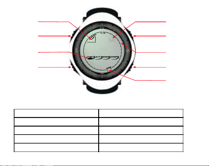
%DURPHWHU
7UHQ G
,QGLFDWRU
6(/(&7
%87721
0RGH
,QGLFDWRU
Field 1
Field 2
%XEEOH/HYHO
$GYL]RU
02'(
%87721
2XWHU
&LUFXPIHUHQFH
%87721
Field 3
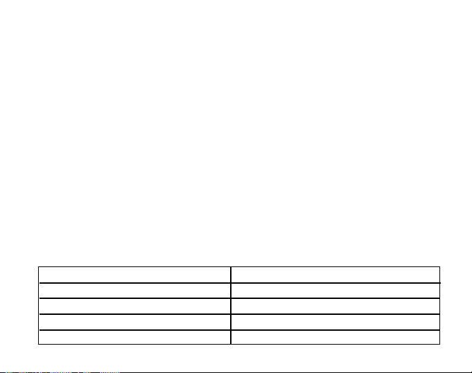
1.5 MEASUREMENTS AND UNITS
The Wristop Computer supplies two units of measure: metric or imperial.
Metric Unit of Measure Imperial Unit of Measure
mft
m/min ft/min
°C °F
mbar InHg
9
%87721
+50,QGLFDWRU
Page 17

1.5.1 Selecting the Units of Measurement
To change the units of measure displayed:
1. Check the mode indicator. If the mode arrow is not on TIME, PRESS the [Mode] button until the arrow is
directly below TIME.
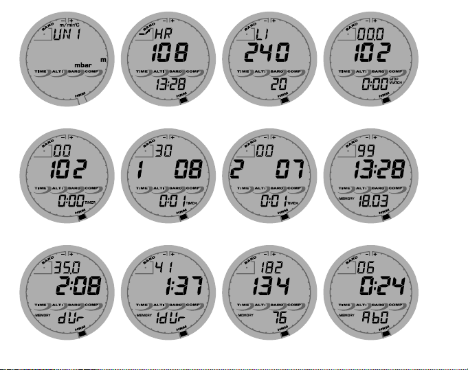
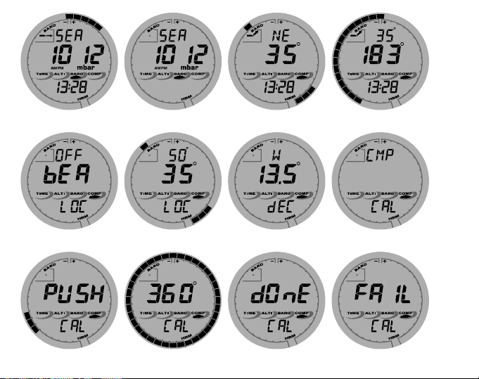
2. PRESS the [Mode] and [Select] buttons simultaneously and hold for 3 seconds. Field 1 will display SET
momentarily and then display UNI (Fig. 1).
WARNING: If the user presses the [Select] button (and does not hold in for 3 seconds) while in the UNI setting
mode, the user will be in the Pressure Sensor Calibration. Refer to the next sub-section for details.
3. PRESS the [Select] button and hold in for 2 seconds. Located to the right in Field 2, m or ft will begin to
flash.
4. PRESS the [+] button to toggle between m and ft.
5. At the unit of measure desired, PRESS the [Select] button to move to the next unit. Located below the m or
ft in Field 2, mbar or inHg will begin to flash.
6. PRESS the [+] button to toggle between mbar and inHg.
7. At the unit of measure desired, PRESS the [Select] button to move to the next unit. Located at the top right
in Field 1 (just above the bubble),
8. PRESS the [+] button to toggle between °C and °F.
9. At the unit of measure desired, PRESS the [Select] button to move to the next unit. Located at the top center
in Field 1, m/min or ft/min will begin to flash.
10.PRESS the [+] button to toggle between m/min and ft/min.
11.At the unit of measure desired, PRESS the [Mode] button to accept the changes. PRESS the [Mode] button
again to return to the main time mode.
Selecting the units of measurement is complete.
Note: If the user does not press any button for 1 minute in the setup mode, the display will automatically exit
setup.
O
C or OF will begin to flash.
10
Page 18

1.6 PRESSURE SENSOR CALIBRATION
WARNING: This is a FACTORY CALIBRATION SETTING. Do not enter this mode.
If you enter this mode in error, exit immediately by pressing the [MODE] button to return to the UNI setting
mode. Normally there is no need to alter the calibration.
If the Pressure Setting Calibration has been altered, you can return the factory setting. Proceed as follows: In
the calibration setting mode, scroll the barometric pressure value up or down until text dEF appears. This is
the factory setting. Then exit by pressing [MODE].
1.7 CARE AND MAINTENANCE
Perform only the detailed processes discussed in this manual. Do not perform any other service to the Wristop
Computer or attempt to open the case or remove the buttons or the bezel.
Protect your Wristop Computer from shocks, extreme heat and prolonged exposure to direct sunlight. If not in
use, your Wristop Computer should be stored in a clean, dry environment at room temperature.
The Wristop Computer can be wiped clean with a lightly moistened (warm water) cloth. Applying a mild soap to
the area can clean stubborn stains or marks.
Avoid exposing the Wristop Computer to strong chemicals like gasoline, cleaning solvents, acetone, alcohol,
adhesives, and paint, as they will damage the units seals, case and finish.
Never attempt to take the Wristop Computer apart or service it yourself. Make sure the area around the sensors
(backside of the instrument) is kept free of dirt and sand. Never insert any objects into the sensor openings of
the Wristop Computer.
1.8 SERVICE
When your Wristop Computer needs service, follow the instructions mentioned below.
SENDING INSTRUCTIONS
1. Pack the product carefully to avoid damage.
11
Page 19

2. Include both the Wristop Computer and the transmitter belt. A full periodic check will be done on the whole
product.
3. Include proof of purchase (a receipt or its photocopy) if the product is under warranty.
4. Include a detailed description of the problem.
5. Include your name, return address and daytime telephone number.
6. Ship postage prepaid to your local Suunto dealer or distributor.
1.8.1 Battery Replacement of the Wristop Computer
The Wristop Computer operates on a three-volt lithium cell Type: CR 2430. The maximum life expectancy is
approximately 12-18 months.
A low battery warning indicator is activated when 5-15 percent of the battery capacity is still available. When
this occurs we recommend replacement of the battery.
Extreme cold weather may activate the low battery-warning indicator. Though the indicator is activated, the
battery may not need to be replaced due to this condition. In temperatures above 10
warning indicator is activated, the battery will need to be replaced.
Note: Heavy use of the electroluminescent backlight, the heart rate function, altimeter, and compass will
significantly reduce the life of the battery.
To replace the battery:
1. flip over the Wristop Computer to view the backside;
2. insert a coin in the coin slot located on the battery compartment cover;
3. turn the coin counterclockwise to the open position marked on the back of the case;
4. remove the battery compartment cover;
5. remove the old cell from the battery compartment and ensure the O-ring and all surfaces are clean, dry and
not damaged. Do not stretch the O-ring.
6. place the new cell into the battery compartment (negative side down, positive side up);
7. ensure that the O-ring is in place to keep the Wristop Computer waterproof and place the battery compartment
cover back onto the backside of the Wristop Computer;
12
O
C (50OF) if the low battery
Page 20

8. insert a coin back into the coin slot; and
9. turn the coin clockwise to the close position marked on the back of the case.
Note: Battery replacement should be performed with extreme care so as to ensure the Wristop Computer
continues to remain waterproof. It is the operators responsibility to take due care to ensure that the Wristop
Computer remains waterproof.
Note: After every battery replacement, it is necessary to calibrate the magnetic sensor. Details on performing
this process are found in Calibrating the Compass section of this manual.
1.8.2 Batter y Replacement of the Suunto Transmitter Belt
The Suunto transmitter belt batterys average expected life is 300 hours. When the battery life has exhausted,
the user can replace the battery by following the same instructions that are given concerning the battery
replacement of the Wristop Computer.
CHAPTER 2 HEART RATE MONITOR
Suunto Advizor/Metron is available with or without Suunto transmitter belt.
The transmitter features:
Battery type: CR 2032 (replaceable by the user).
Battery life: approximately 300 hours.
Available in different sizes.
The Suunto transmitter belt has to be sent along with the Wristop Computer in case of maintenance.
2.1 SUUNTO WRISTOP COMPUTER AND TRANSMITTER IN
A WATER ENVIRONMENT
Suunto Wristop Computer is water proof to a depth of 30m/100ft. To maintain the water resistance, it is strongly
recommended to have all service done by authorised Suunto service personnel.
13
Page 21

Heart rate measurement in a water environment is technically demanding for the following reasons:
Pool water with a high chlorine content and seawater may be very conductive and the electrodes of the
transmitter may get short circuited and ECG (ECG = electrocardiogram) signals cannot be detected by the
transmitter unit.
Jumping into the water or strenuous muscle movement during competitive swimming may cause water
resistance that shifts the transmitter on the body to a location where it is not possible to pick up the ECG
signal.
The ECG signal strength varies depending on the individuals tissue composition and the percentage of
people who have problems with heart rate measurement is considerably higher in a water environment than
in other use.
Note: The Wristop Computer is not a dive instrument, and therefore buttons should not be operated (put to use)
while under water.
2.2 SUUNTO WRISTOP COMPUTER AND INTERFERENCE
ELECTROMAGNETIC INTERFERENCE
Disturbances may occur near high voltage power lines, traffic lights, overhead lines of electric railways, electric
bus lines or trams, televisions, car motors, bike computers, some motor driven exercise equipment, cellular
phones or when you walk through electric security gates.
Electromagnetic interference may cause inaccuracy in receiving heart rate signals. The sum of the above,
below and in heart rate values may be shorter than the total elapsed time. The reason for this inaccuracy is
that the electromagnetic interference may prevent the Wristop Computer from receiving signals of the transmitter
belt perfectly.
2.3 WARNINGS
Persons who have a pacemaker, defibrillator or other implanted electronic device use the Heart Rate Monitor
at their own risk. Before starting the initial use of the Heart Rate Monitor, we highly recommend an exercise
test under a doctors supervision. This will ensure the safety and reliability of the pacemaker and Heart Rate
Monitor when simultaneously being used.
14
Page 22

Exercise may include some risk, especially for those who have been sedentary. We strongly advise consulting
your doctor prior to beginning a regular exercise program.
Disturbances may occur near high voltage power lines, televisions, cars, bike computers, motor driven
exercise equipment or cell phones.
It is best to position the Wristop Computer within 3 feet or 1 meter of the transmitter. Ensure no other
transmitters are within that range; signals from another transmitter(s) can cause an incorrect readout.
2.4 CARE
Wash the transmitter regularly with mild soap and water after each use. Rinse with pure water; dry thoroughly
and carefully.
Store in a cool dry place. Never store the transmitter wet. Moisture keeps the electrodes wet and transmitter
activated thereby shortening the life of the battery.
Do not bend or stretch the transmitter; this may damage the electrodes.
2.5 ACTIVATING THE HEART RATE MONITOR
1. Attach the transmitter to the elastic strap.
2. Adjust the strap length to fit snugly and comfortably. Secure the strap around your chest, below the chest
muscles. Lock the buckle.
3. Raise the transmitter a little off your chest and wet the grooved electrode areas on the back of it. It is
important that the electrodes are wet during exercise.
4. Check that the wet electrode areas are firmly against your skin and the logo is in a central upright position.
5. Wear the wristop computer as you would wear an ordinary watch.
Note: It is recommended that you wear the transmitter against your bare skin to ensure flawless operation.
However, if you wish to wear the transmitter over a shirt, moisten the shirt well under the electrodes.
When the Wristop Computer is in the Altimeter main mode, HRM main mode or any of the HRM sub modes and
the transmitter is worn, the Wristop Computer will automatically search for a heart rate signal. This procedure
also initiates the heart rate measurement.
15
Page 23

During the first minute, measurements are taken every second, then for the next 4 minutes every 5 seconds. If
no heart rate signal has been received during the first five minutes, the search for a heart rate signal will end.
After this process, the user can manually activate the heart rate measurement by pressing the [+] button in the
HRM main mode.
NOTE: Pressing the [+] button during the first 5 minutes in the heart rate mode, will stop the search for a heart
rate signal. To reactivate the measurement, press the [+] button again.
2.6 OPERATION
The Heart Rate Monitor function provides the user with:
a heart rate range from 20 - 240 beats/min;
a stopwatch range of up to 23:59.59, stores up to 30 split times and heart rate readings;
an interval countdown timer range of up to 23:59.59;
upper and lower limits adjustable in one beat increments to set target heart rate zone;
audible alarms alert the user of exceeding upper or lower limit;
heart rate displayed in relation to current time or running time (stopwatch and countdown timer);
auto-repeat of countdown timer for interval training (training interval, recovery interval, number of intervals);
and
HRM memory activated from the starting of the stopwatch or the countdown timer storing total training time,
maximum, minimum and average heart rate during training, as well as time spent in, above and below target
heart rate zone. When stopwatch is used, the memory also stores up to 30 split times and heart rates for
viewing.
To view and use the Heart Rate Monitor function:
Check the LCD. If the segment under HRM is not highlighted, PRESS the [Mode] button until the segment
directly under HRM is lit.
In the HRM mode (Fig. 2):
Field 1 displays the text HR (HR = heart rate).
16
Page 24

Field 2 displays the current heart rate.
Field 3 displays the current time.
Note: In order to activate this feature, the transmitter belt must be worn around the chest area. The middle row
will show zero until there is a proper reading to display.
2.6.1 How to Set the Target Zones of the Heart Rate Monitor
To set the upper and lower limits in the HRM mode:
1. PRESS the [Select] button and hold for 2 seconds.
Field 1 displays the text LI (LI = Limits).
Field 2 displays the text OFF.
2. PRESS the [+] button or the [-] button to toggle between off and on. Choose On to activate the audible
heart rate limit alarms.
3. PRESS the [Select] button to move to the next setting (setting the upper limit) (Fig. 3).
Field 1 displays the text LI (LI = Limits).
Field 2 flashes the upper limit where the default value is 240.
Field 3 displays the lower limit.
4. PRESS the [+] button to scroll the value upward or PRESS the [-] button to scroll the value downward.
5. At the value desired, PRESS the [Select] button to accept the upper limit value and move to the next setting
(setting the lower limit) (Fig. 3).
Field 1 displays the text LI (LI = Limits).
Field 2 displays the new upper limit setting.
Field 3 flashes the lower limit where the default value is 20.
6. PRESS the [+] button to scroll the lower limit value upward or PRESS the [-] button to scroll the value
downward.
7. At the value desired, PRESS the [Mode] button to accept the upper and lower limits and exit.
The HRM target heart rate zone is set.
17
Page 25

Limits On means that the Wristop Computer will audibly alert the user that a chosen upper or lower limit has
been exceeded. Limits OFF means that the Wristop Computer will not alert the user, but the limits will however
be used to calculate time spent in, above and below the target heart rate zone.
The outer circumference will graphically show the heart rate level reached by the user, in relation to the heart
rate limit set. The circumference will adjust to equal any limit settings starting from the 12 oclock position going
clockwise. E.g. if the upper limit is set to 140 beats/minute and the lower limit to 130 beats/minute, one full circle
on the outer circumference will equal 10 beats/minute.
2.7 STOPWATCH SUB MODE
The Wristop Computer stopwatch feature can provide split time measurement up to 23 hours 59 minutes and
59 seconds up to 30 split times and heart rate readings can be stored into the HRM memory.
In the HRM mode, PRESS the [Select] button once to enter this submode.
In the Stopwatch mode (Fig. 4):
Field 1 displays the seconds and tenths of a second,
Field 2 displays the current heart rate, and
Field 3 displays hours and minutes and to the far right stopwatch.
Note: When the transmitter is not worn, Field 2 displays the current time.
The HRM memory for one event is automatically activated when starting the stopwatch (or countdown timer).
The memory stores total training time, maximum, minimum and average heart rate during training, as well as
time spent in, above and below the target heart rate zone for one event. The next time the stopwatch (or
countdown timer) is activated, the previous events information will be erased.
2.7.1 How to Use the Stopwatch
There are three timing modes the user can employ:
an elapsed time measurement;
a split time measurement; and
a finish time measurement for up to 30 runners.
18
Page 26
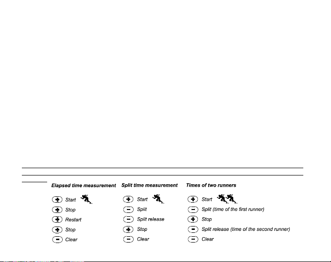
In the elapsed time mode:
1. PRESS the [+] button to start, stop, and restart the stopwatch in the stopwatch sub mode.
2. PRESS the [-] button to reset the stopwatch to zero once the stopwatch has stopped.
In the split time mode:
1. PRESS the [+] button to start the stopwatch.
2. PRESS the [-] button once to stop the stopwatch and to display a split time. This split time and the
momentaneous heart rate reading will be stored in the memory for later viewing. The stopwatch will
automatically start running after displaying the split time for 5 seconds. Repeat this procedure for each split
time.
3. PRESS the [+] button to stop the stopwatch.
4. PRESS the [-] button to reset the stopwatch to zero once the stopwatch has been stopped.
In the two finish time mode:
1. PRESS the [+] button to start the stopwatch.
2. PRESS the [-] button once to stop the stopwatch and to display the first finish time. This finnish time will be
stored in the memory for later viewing. The stopwatch will automatically start running after displaying the
finish time for 5 seconds. Repeat this procedure for each runner.
3. PRESS the [+] button to stop the stopwatch.
4. PRESS the [-] button to reset the stopwatch to zero once the stopwatch has been stopped.
Note: If the user is in other modes or submodes when the stopwatch function is activated, the stopwatch will
continue and remain in the background. A flashing stopwatch text in Field 3 indicates that the stopwatch is still
activated.
19
Page 27

2.8 INTERVAL COUNTDOWN TIMER SUB MODE
In the HRM mode, PRESS the [Select] button twice to enter this sub mode.
In the interval countdown timer mode (Fig. 5):
Field 1 displays the seconds,
Field 2 displays the current heart rate, and
Field 3 displays the hour and minutes with the text TIMER located to the right.
Note: When the transmitter is not worn, Field 2 displays the current time.
The HRM memory for one event is automatically activated when starting the countdown timer (or stopwatch).
The memory stores total training time, training interval duration (1dur), maximum, minimum and average heart
rate during training, as well as time spent in, above and below target heart rate zone for one event. The next
time the countdown timer (or stopwatch) is activated, the previous events information will be erased.
There are two types of intervals: training and recovery. The countdown timer can be set to repeat a specific
interval a specific number of times automatically. Adjustments to training interval, recovery interval and
number of intervals can be made through the setup process.
Please note that the HRM memory will only store heart rate information for the training intervals.
2.8.1 How to Set the Countdown Timer
In the Interval Countdown Timer mode:
1. PRESS the [Select] button and hold in for 2 seconds. The first page is the training interval (Fig. 6).
Field 1 displays the seconds;
Field 2 displays the number 1 indicating the training interval and the number of intervals up to
99; and
Field 3 displays the hours and minutes up to 23:59 and the text TIMER.
2. PRESS the [+] button to scroll the seconds upward or PRESS the [-] button to scroll the seconds downward.
3. At the seconds desired, PRESS the [Select] button to move to the next setting. Located on right of Field 3,
the minutes will begin to flash.
20
Page 28

4. PRESS the [+] button to scroll the minutes upward or PRESS the [-] button to scroll the minutes downward.
5. At the minutes desired, PRESS the [Select] button to move to the next setting. Located in the center of Field
3, the hour will begin to flash.
6. PRESS the [+] button to scroll the hour upward or PRESS the [-] button to scroll the hour downward.
7. At the hour value desired, PRESS the [Select] button to move to the next setting. Located in Field 2, the
number of intervals can be chosen.
8. PRESS the [+] button to increase the number of intervals up to 99 or PRESS the [-] button to decrease the
# of intervals desired. If no repeats of the interval are desired adjust this value to read 01.
9. At the number of intervals desired, PRESS the [Select] button to move to the second page. The second
page is the recovery interval (Fig. 7).
Field 1 displays the seconds;
Field 2 displays the number 2 indicating the Recovery Interval; and
Field 3 displays the hours and minutes up to 23:59 and the text TIMER.
10.PRESS the [+] button to scroll the seconds upward or PRESS the [-] button to scroll the seconds downward.
11.At the seconds desired, PRESS the [Select] button to move to the next setting. Located on right of Field 3,
the minutes will begin to flash.
12.PRESS the [+] button to scroll the minutes upward or PRESS the [-] button to scroll the minutes downward.
13.At the minutes desired, PRESS the [Select] button to move to the next setting. Located in the center of Field
3, the hour will begin to flash.
14.PRESS the [+] button to scroll the hour upward or PRESS the [-] button to scroll the hour downward.
15.At the hour value desired, PRESS the [Mode] button to accept the changes and exit the setup program.
The interval countdown timer setup for Training and Recovery is complete.
2.8.2 How to Start the Countdown Timer
During the training interval, the set heart rate limits are in use and the heart rate information is calculated and
stored in the HRM memory. When the time has been counted down, a beep is heard, and simultaneously a new
interval will begin.
21
Page 29

If the recovery interval has a value other than zero, this interval will now be counted down. During the recovery
interval the heart rate is displayed, but not measured nor stored for later calculations and will not effect max/
min/average heart rate readings nor the time spent in/above/below the target zone readings. The limits established
are not in use during this interval either.
If the recovery interval has been set to 0, another training interval is immediately started. This interval is
repeated as many times as set in the setup of the countdown timer. When the last interval is completed, a triplebeep is heard signifying to the user the end of the countdown timer process.
To start the countdown timer:
1. PRESS the [+] button to start, stop, and restart the timer in the countdown timer sub mode.
2. During an activity, PRESS the [-] button to view the number of intervals remaining. This will be displayed in
Field 2.
3. Once the timer has stopped, PRESS the [-] button to reset the timer to zero.
Note: If the user is in other modes or sub modes when the countdown time has been activated, the countdown
timer will continue and remain in the background. A flashing timer text in Field 3 indicates that the timer is still
activated.
2.9 HRM MEMORY
The HRM memory sub mode stores the maximum, minimum, and average heart rates during selected intervals
(training or recovery), as well as the time spent in, above and below selected heart rates (target zones). If the
heart rate goes beyond the selected zone, an alarm sounds.
To view the HRM Memory, in the HRM mode, PRESS the [Select] button three times to enter this submode.
In the HRM Memory mode, there are six display screens.
1. In the first display (main display) (Fig. 8):
Field 1 displays the year of the start date;
Field 2 displays the start time; and
Field 3 displays the start date.
22
Page 30

2. In the second display (duration of the event) (Fig. 9):
Field 1 displays the seconds of training time;
Field 2 displays the hours and minutes of the training time; and
Field 3 displays the text dUr (dUr = duration of the event).
3. In the third display (duration of the training intervals) (Fig. 10):
Field 1 displays the seconds of training time;
Field 2 displays the hours and minutes of the training time; and
Field 3 displays the text 1dUr (1dUr = duration of the training intervals).
Note: The third display will be shown only when the countdown timer is used.
4. In the fourth display (heart rate information): (Fig. 11)
Field 1 displays the maximum heart rate recorded;
Field 2 displays the average heart recorded; and
Field 3 displays the minimum heart rate recorded.
5. In the fifth display (time spent above the target heart rate zone) (Fig. 12):
Field 1 displays the seconds;
Field 2 displays the hours and minutes; and
Field 3 displays the text AbO (AbO = above target heart rate).
6. In the sixth display (time spent in the target heart rate zone) (Fig. 13):
Field 1 displays the seconds;
Field 2 displays the hours and minutes; and
Field 3 displays the text In (In = within the target heart rate).
7. In the seventh display (time spent below the target heart rate zone) (Fig 14):
Field 1 displays the seconds;
Field 2 displays the hours and minutes; and
Field 3 displays the text bEL (bEL = below target heart rate).
23
Page 31

Note: The HRM memory is for one event only. This feature is automatically activated when starting the stopwatch
or countdown timer and will cause the previous events information to be erased.
To view the split times and heart rate readings stored in the memory when using the stopwatch, hold the
[Select] button in for 2 seconds when on any of the HRM memory displays.
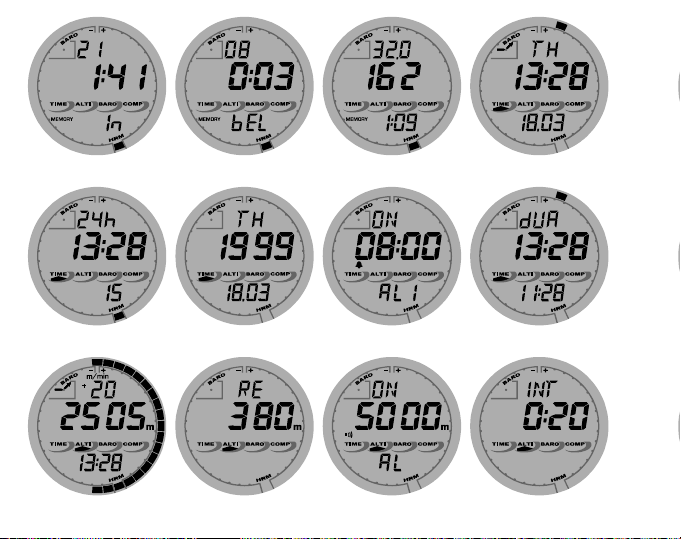
The display shows the following information (Fig. 15):
Field 1 displays seconds and tenths of seconds of the stopwatch;
Field 2 displays your momentaneous heart rate; and
Field 3 displays hours and minutes of the stopwatch.
Press the [+] button to scroll through the stored split times and heart rate readings.
You can exit the viewing of stored split times and heart rate readings at any time by pressing the [Mode] button.
CHAPTER 3 TIME MODE
The Suunto Wristop Computer watch function provides the user with:
an adjustable 24/12 hour clock display;
a calendar pre-programmed to the year 2089;
three daily alarms; and
a dual time operation.
To view and use the Time mode function:
Check the Mode Indicator arrow. If the mode arrow is not on TIME, PRESS the [Mode] button until the arrow is
directly below TIME.
In the TIME mode (Fig. 16):
Field 1 displays the day of the week.
Field 2 displays the current time.
Field 3 displays the date (month/day if the 12-hour clock has been chosen; day/month if the 24-hour clock
has been chosen).
24
Page 32

The Outer Circumference graphically displays time in seconds.
The TIME mode and all sub modes can be adjusted through the setup program of the Wristop Computer.
3.1 HOW TO SET THE TIME
To set the Time:
1. PRESS the [Select] button and hold in for 2 seconds. Located in Field 3, the seconds will begin to flash (Fig.
17).
2. PRESS the [+] button to scroll the seconds upward or PRESS the [-] button to reset the seconds to zero.
3. At the seconds desired, PRESS the [Select] button to move to the next setting. Located on right of Field 2,
the minutes will begin to flash.
4. PRESS the [+] button to scroll the minutes upward or PRESS the [-] button to scroll the minutes downward.
5. At the minutes desired, PRESS the [Select] button to move to the next setting. Located in the center of Field
2, the hour will begin to flash.
6. PRESS the [+] button to scroll the hour upward or PRESS the [-] button to scroll the hour downward.
7. At the hour desired, PRESS the [Select] button to move to the next setting. Located in Field 1, the 24 or 12
hour clock setting will begin to flash.
8. PRESS either the [+] or the [-] button to toggle between the 24hr and 12hr.
Note: if the 12 hour clock is chosen either AM/PM will appear below the hour in Field 2.
9. At the clock setting desired, PRESS the [Select] button to move to the next setting. Located in the center of
Field 2, the year will begin to flash (Fig. 18).
10.PRESS the [+] button to scroll the year upward or PRESS the [-] button to scroll the year downward.
11.At the year desired, PRESS the [Select] button to move to the next setting. Located in the center of Field 3,
the month represented by a number will begin to flash.
12.PRESS the [+] button to scroll the month upward or PRESS the [-] button to scroll the month downward.
13.At the month desired, PRESS the [Select] button to move to the next setting. Located to the right of Field 3,
the day will begin to flash.
14.PRESS the [+] button to scroll the day upward or PRESS the [-] button to scroll the date downward.
25
Page 33

Note: Once the user has determined the year, month and day, Wristop Computer will supply the day of the
week in Field 1.
Note: If the 12-hour clock is chosen, the date will be displayed as month/day. If the 24-hour clock is chosen, the
date will be displayed day/month.
15.At the desired day, PRESS the [Mode] button to accept the changes and return to the main mode.
Note: If the user does not press any button for 1 minute in the setup mode, the display will automatically exit
setup.
Setting the time is now complete.
3.2 DAILY ALARM SUB MODE
The Daily Alarm sub mode allows the user to select and set up to 3 alarms. The alarm volume cannot be
changed.
In the TIME mode, PRESS the [Select] button once to enter this sub mode.
In the Daily Alarm mode (Fig. 19):
Field 1 displays ON or OFF (the activation status of a particular alarm),
Field 2 displays the time of a particular alarm, and
Field 3 displays the alarm (1, 2, or 3) the user is viewing.
Pressing the [+] or the [-] button will toggle between the alarms 1, 2, or 3 to view the settings for each alarm.
3.2.1 How to Set the Daily Alar ms
1. PRESS the [+] or the [-] button to select the desired alarm to be set (1, 2, or 3).
2. PRESS the [Select] button and hold in for 2 seconds. Located in Field 1, the ON or OFF will begin to
flash.
3. PRESS either the [+] or the [-] button to toggle between ON and OFF.
4. At the setting desired, PRESS the [Select] button to move to the next setting. Located in the center of Field
2, the hour will begin to flash.
26
Page 34

5. PRESS the [+] button to scroll the hour upward or PRESS the [-] button to scroll the hour downward.
6. At the hour desired, PRESS the [Select] button to move to the next setting. Located on the right of Field 2,
the minutes will begin to flash.
7. PRESS the [+] button to scroll the minutes upward or PRESS the [-] button to scroll the minutes downward.
8. At the minutes desired, PRESS the [Mode] button to accept the changes and exit the setup program. A small
bell will appear at the bottom left side in Field 2 to signify an alarm has been activated.
The Alarm setup is complete. To activate up to three alarms, please repeat steps 1-8 for the selected alarm (1,
2, or 3).
3.3 DUAL TIME SUB MODE
The Dual Time sub mode allows you to set the watch to display a time other than the main one.
In the TIME mode, PRESS the [Select] button twice to enter this sub mode.
In the dual time mode (Fig. 20):
Field 1 displays dUA indicating dual time,
Field 2 displays the current time, and
Field 3 displays the dual time (e.g. your home time).
The user can display the seconds while in this sub mode by pressing the [+] button, in Field 3 the seconds will
appear for 10 seconds. Afterwards the display returns to showing the dual time.
3.3.1 Setting the Dual Time Function
In the dual time mode:
1. PRESS the [Select] button and hold in for 2 seconds. Located in Field 3, the hours will begin to flash.
2. PRESS the [+] button to scroll the hours upward or PRESS the [-] button to scroll the hours downward.
3. At the hour desired, PRESS the [Select] button to move to the next setting. Located in Field 3 to the right of
the hour value, the minutes will begin to flash.
4. PRESS the [+] button to scroll the minutes upward or PRESS the [-] button to scroll the minutes downward.
27
Page 35

5. At the minutes desired, PRESS the [Mode] button to accept the changes and exit the setup program.
The dual time setup is complete.
The dual time stays the same, even though the time in the main time mode is adjusted. For example, if you set
the dual time to show your home time, your home time will always be displayed in this sub mode even though
you travel to a different time zone and adjust the time in the main time mode.
Note: The dual time function is completely independent and does not effect the alarms or the memory functions.
These are dependent on the current local time.
CHAPTER 4 ALTIMETER MODE
The Suunto Wristop Computer Altimeter function provides the user with:
an adjustable unit of measure either meter or feet: meter ranging from -500 to 9,000; ft ranging -1,600 to
29,500;
a resolution of 5m or 10ft;
a display update on the rate of vertical movement in intervals of one second for 3 minutes, then every 10
seconds or less;
a difference measurement function allowing zeroing of the altimeter for following vertical progress between
stages;
an automatic 24-hour memory in one hour intervals showing altitude and vertical ascent/descent rate; and
A logbook of recordings storing total vertical ascent/descent, average vertical ascent/descent rate, number
of runs (e.g. skied), duration of log, as well as minimum, maximum and average heart rate during log, and
time spent in, above and below target heart rate zone.
To view and use the Altimeter function:
Check the Mode Indicator arrow. If the mode arrow is not on ALTI, PRESS the [Mode] button until the arrow is
directly below ALTI.
In the ALTIMETER mode (Fig. 21):
Field 1 displays the vertical ascent or descent rate;
28
Page 36

Field 2 displays the current altitude in increments of 5 meters or 10 feet (depending on the unit of measure
selected); and
Field 3 displays the current time or the current heart rate if the transmitter is worn.
The Outer Circumference graphically displays the altitude in hundreds of meters or feet over a full thousand
where one complete circle is equivalent to 1000.
Note: In order for the HRM feature to be activated the user must be wearing the transmitter belt around his/her
chest. The HRM indicator in the lower right section of the LCD flashes according to the measured heart rate
(beats/minute). Refer to Section 2 Heart Rate Monitor for details in setting and activiting this feature.
When wearing the belt, the current time can be viewed for 10 seconds by pressing the [+] button. If the belt is
not worn, the current time is shown on the bottom row (Field 3), in place of the heart rate.
IMPORTANT NOTE: In order to set the altitude in the Altimeter mode, the altitude must be known. That information
can be found by utilizing a topographical map identifying the current location with the associated altitude marked.
The user can then proceed and follow the instructions, setting the altimeter, provided in the section below.
DETAILS REGARDING THE EFFECT OF AIR TEMPERATURE ON ALTITUDE MEASUREMENT ARE SHOWN
ON PAGE 50 OF THIS MANUAL.
IF THE ALTITUDE IS NOT KNOWN, THE USER CAN SET THE SEA LEVEL PRESSURE IN THE
BAROMETER MODE (refer to page 39, Setting the Sea Level Pressure).
SETTING THE SEA LEVEL PRESSURE WILL ADJUST THE ALTIMETER TO THE CURRENT ALTITUDE
WITHIN APPROXIMATELY TEN METERS OR 30 ft. A 1-mbar CHANGE RESULTS APPROXIMATELY AN 8METER (OR 26 ft) CHANGE IN ALTITUDE, AND A 0,05 inHG CHANGE RESULTS A 45 ft. CHANGE IN
ALTITUDE.
INFORMATION ON THE CURRENT SEA LEVEL PRESSURE CAN BE OBTAINED THROUGH NEWSPAPERS,
LOCAL NEWS AND RADIO WEATHER REPORTS, THE LOCAL AIRPORT FACILITY OR THROUGH THE
INTERNET UNDER LOCAL WEATHER.
29
Page 37
4.1 SETTING THE ALTIMETER
In setting the Altimeter, there are three processes that can be performed: the Reference Altitude (known altitude
at the current location); Altitude Alarm (signals the user when a certain altitude, programmed, is reached); and
Logbook Recording Interval (allows the user to view the altitude, average rate of vertical movement and heart
rate within a chosen interval of time).
1. PRESS the [Select] button and hold in for 2 seconds. Located in Field 1 is the text RE (indicating reference
altitude), located in Field 2, the current altitude will begin to flash (Fig. 22).
2. PRESS the [+] button to scroll the altitude upward or PRESS the [-] button to scroll the altitude downwards.
3. At the desired reference altitude, either PRESS the [Mode] button to accept the changes and return to the
main mode or PRESS the [Select] button to move to the next setting. Located in Field 1, the ON or OFF
will begin to flash (Fig. 23).
4. PRESS either the [+] or the [-] button to toggle between the ON and OFF for the Altitude Alarm.
5. At the desired setting, PRESS the [Select] button to move to the next setting. Located in the center of Field
2, the alarm altitude will begin to flash.
6. PRESS the [+] button to scroll the altitude upward or PRESS the [-] button to scroll the altitude downwards.
7. At the desired altitude, either PRESS the [Mode] button to accept the changes and return to the main mode
or PRESS the [Select] button to move to the next setting. Located in Field 1, the text INT and located in Field
2 the time interval will begin to flash (Fig. 24).
8. PRESS either the [+] or the [-] button to scroll through the intervals. There are four time intervals: 20 seconds,
1 minute, 10 minute or 60 minutes.
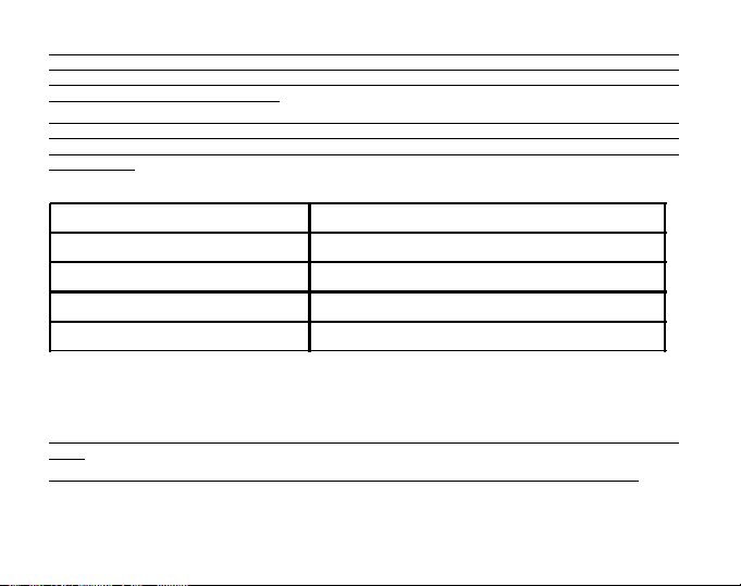
Recommended interval to use:
ACTIVITY INTERVAL
Skiing 20 sec or 1 minute
Biking 20 sec or 1 minute
Hiking 10 minute
Mountaineering 10 minute or 60 minute
30
Page 38
Note: In selecting the interval, the user chooses a) the time period for recording the altitude, the vertical ascent/
descent rate as well as the heart rate to be stored into the logbook and b) the timeout or maximum recording
time of a logbook. The shorter the interval the more accurate the information due to the fact the sampling rate
is faster. Timeouts are discussed below.
Note: If the logbook is recording, based on the interval chosen, the logbook will record up to that particular time
period. Once the time period has been reached, the Wristop Computer will alert the user that the logbook
recording has expired (known as a timeout). For setting the logbook interval refer to Setting the Altimeter on
previous page.
The timeouts are as follows:
LOGBOOK INTERVAL MAX. CONTINUOUS RECORDING TIME
20 Second 10 hours
1 minute 12 hours
10 minute 7 days
60 m inute 10 days
9. At the desired interval, PRESS the [Mode] button to accept the changes and exit the setup program.
Once the user completes the process in setting the reference altitude of the current location to the known
altitude, the Wristop Computer will also correct the sea level pressure, and therefore, it will not be necessary for
this function to be set.
Note: If the user does not press any button for 1 minute in the setup mode, the display will automatically exit
setup.
Note: A 10 minute recording interval means that the Wristop Computer records data every 10 minutes.
31
Page 39

4.2 ALTITUDE DIFFERENCE MEASUREMENT SUB MODE
In the Altimeter mode, PRESS the [Select] button once to enter this sub mode.
In the Altitude Difference measurement mode (Fig. 25):
Field 1 displays the vertical ascent or descent rate;
Field 2 displays the current altitude in increments of 5 meters or 10 feet depending on the unit of measure
selected; and
Field 3 displays the running time; to the left of the time is the text differ.
The Outer Circumference graphically displays the altitude in hundreds of meters or feet over a full thousand
where one complete circle is equivalent to 1000.
The running time is displayed up to 39 hours and 59 minutes; after which three dashes (-:--) appear on the
display in Field 3. If the user allows the difference measurement sub mode to remain on visual display continuously
for 12 hours, Wristop Computer will after this period automatically return to the main time mode.
This mode does continue in the background and allows the user to move to other modes. The user can return
to this sub mode to view the current status at his/her convenience.
Note: The difference measurement mode is a relative measurement. Any change in the reference altitude
during the altitude difference measurement will effect the measured altitude. We recommend that the reference
altitude always be checked and set again prior to beginning a new measurement.
4.2.1 How to Start the Altitude Difference Measurement
1. PRESS the [Select] button and hold in for 2 seconds. Located in Field 1 is the text SET; located in Field 2,
zero will begin to flash (Fig. 26).
2. PRESS the [Mode] button to accept the flashing zero and start the difference measurement.
If the user does not want to set the altitude difference to zero to restart the difference measurement, PRESS
either the [+] or the [-] button to return to the original altitude difference reading and then PRESS the [Mode]
button to validate that reading.
Note: If the user does not press any button for 1 minute in the setup mode, the display will return to the main
mode without zeroing the altimeter.
32
Page 40

4.3 24-HOUR MEMORY SUB MODE
In the Altimeter mode, PRESS the [Select] button twice to enter this sub mode.
In the 24-hour memory mode (Fig. 27):
Field 1 displays the vertical ascent or descent rate;
Field 2 displays the current altitude in increments of 5 meters or 10 feet, depending on the unit of measure
selected ; and
Field 3 displays the particular hour and to the left the text memory.
The Outer Circumference displays graphically the altitude in hundreds of meters or feet over a full thousand
where one complete circle is equivalent to 1000.
To view the information compiled in the 24-hr memory:
1. PRESS the [-] button to scroll back down in increments of one hour and view the vertical ascent/descent
rate and the altitude for that particular hour.
2. PRESS the [+] button to scroll back up.
Note: Replacing the battery will not erase this information.
4.4 LOGBOOK SUB MODE
In the Altimeter mode, PRESS the [Select] button three times to enter this sub mode. In the logbook mode, nine
summarizing displays are shown. The displays automatically rotate showing the first display for 7 seconds then
proceeds to show the next displays at 4 second intervals.
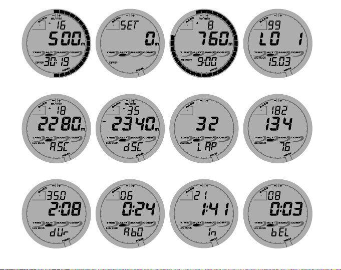
In the first display (Fig. 28):
Field 1 displays the year;
Field 2 displays the text LO with the current logbook number flashing; and
Field 3 displays the month and day of the particular logbook number. To the left of the month/day, is the text
Log Book.
The user can PRESS the [-] to scroll down to view previous logs captured and then PRESS [+] to scroll up to
view the most current logbook.
33
Page 41

The second display shows the ascent information for the particular logbook that is being viewed (Fig. 29).
Field 1 displays the average vertical ascent rate during the event;
Field 2 displays the total vertical ascent ; and
Field 3 displays the text ASC along with the text Log Book to the left.
The third display shows the descent information for the particular logbook that is being viewed (Fig. 30).
Field 1 displays the average vertical descent rate during the event;
Field 2 displays the total vertical descent; and
Field 3 displays the text dSC along with the text Log Book to the left.
The fourth display shows the number of laps (runs, ascents and descents) completed for the particular logbook
that is being viewed (Fig. 31).
Field 2 displays the total number of laps; and
Field 3 displays the text LAP along with the text Log Book to the left.
Note: A Lap is a vertical movement of ascent and descent equaling 150 ft/50m or more.
The fifth display shows the time duration of recording information in the particular logbook that is being viewed
(Fig. 32).
Field 2 displays the total time of the log ; and
Field 3 displays the text dUr along with the text Log Book to the left.
The sixth display shows the heart rate information recorded in the particular logbook that is being viewed (Fig.
33).
Field 1 displays the maximum heart rate during the event;
Field 2 displays the average heart rate; and
Field 3 displays the minimum heart rate along with the one segment highlighted under HRM.
The seventh display shows the time spent above the target HR zone selected (Fig. 34).
Field 1 displays the seconds;
34
Page 42

Field 2 displays the time spent above the target HR zone; and
Field 3 displays the text AbO (AbO=above) along with the one segment highlighted under HRM.
The eigth display shows the time spent in the target HR zone selected (Fig. 35).
Field 1 displays the seconds;
Field 2 displays the time spent in the target HR zone; and
Field 3 displays the text In (In=within target zone) along with the one segment highlighted under HRM.
The ninth display shows the time spent below the target HR zone selected (Fig. 36).
Field 1 displays the seconds;
Field 2 displays the time spent below the target HR zone; and
Field 3 displays the text bEL (bEL=below) along with the one segment highlighted under HRM.
Note: the maximum, minimum and average heart rate values displayed in the logbook, are calculated based on
the chosen recording interval. Please note that these values are more accurate the shorter the recording
interval. The values showed in the logbook will vary from the values displayed in the HRM memory, since the
sampling rate in the HRM memory is always 2 seconds.
Note: If you want greater precision, start new logbooks more often or lower the recording interval.
4.4.1 Closer examination of the logbook
The logbook can also be viewed at the chosen interval. The Closer Examination display shows vertical ascent/
descent rate and heart rate of the user at a specific altitude and selected interval. This display can be accessed
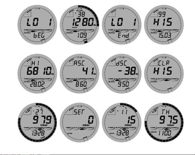
by holding the [Select] button for 2 seconds when in the logbook mode. The text bEG indicating beginning of
log will appear in Field 3 (Fig. 37). Move through the displays by pressing the [+] button.
The display shows the following information (Fig. 38):
Field 1 displays the vertical ascent/descent rate;
Field 2 displays the altitiude; and
Field 3 displays the heart rate along with the one segment highlighted under HRM.
You can exit the closer examination at any time pressing the [MODE] button.
35
Page 43

Note: If the transmitter belt has not been worn during the log recording, Field 3 shows time of measurement.
If the user stops to view a certain display in the closer examination of the logbook, the following information will
start to scroll automatically in Field 3: time of measurement, date, year, heart rate, time etc.
4.4.2 How to Start and Stop a Logbook
In the Altimeter main mode or the difference measurement sub mode, PRESS the [+] button twice within two
seconds. A beep will be heard and the flashing text Log Book will appear in Field 3 to indicate the start of the
recording.
The recording can be stopped by pressing the [+] button twice within two seconds. A beep will be heard and the
Log Book text will be removed from Field 3 indicating recording has stopped.
Logbooks are self-erasing and cannot be cleared by the user.
4.5 LOGBOOK HISTORY SUB MODE
The Logbook history shows a summation of all logs recorded.
In the Altimeter mode, PRESS the [Select] button four times to enter this sub mode. The logbook history mode
features four displays.
In the first display (Fig. 40):
Field 1 displays the year when the logbook history has last been cleared;
Field 2 displays the text HIS; and
Field 3 displays the month and day when the logbook history has last been cleared. To the left of the month/
day, displayed is the text Log Book.
PRESS [+] to scroll through the different displays.
In the second display (Fig. 41):
Field 1 displays the text HI;
Field 2 displays the highest altitude reached since the last clearing date; and
Field 3 displays the date when it was reached with the text Log Book to the left.
36
Page 44

In the third display (Fig. 42):
Field 1 displays the text ASC; and
Field 2 and 3 show up to a 8 digit accumulative vertical ascent since the last reset. Field 2 is activated when
the value of the vertical ascent is beyond the 3 digit value displayed in Field 3.
In the fourth display (Fig. 43):
Field 1 displays the text dSC;
Field 2 and 3 show up to a 8 digit accumulative vertical descent since the last reset. Field 2 is activated
when the value of the vertical descent is beyond the 3 digit value displayed in Field 3.
4.5.1 Clearing the Logbook History
To clear the history of the logbook:
1. In any of the logbook history displays, PRESS the [Select] button and hold in for 2 seconds. Located in Field
1 is the text CLR; in Field 2 the text HIS; and in Field 3, nO will begin to flash (Fig. 44).
2. PRESS the [+] button to toggle between YES and NO.
3. PRESS the [Mode] button to accept the option YES.
The logbook history is erased and a new starting date is set to begin new cumulative measurements.
Note: If the user does not press any button for 1 minute in the setup mode, the display will automatically exit
setup.
We recommend that the logbook history be cleared prior to beginning the first logbook recording ever.
CHAPTER 5 BAROMETER MODE
The Suunto Wristop Computer Barometer function provides the user with:
an adjustable unit of measure mbar or inHg; mbar range 300 to 1,100 mbar, inHg range 8.90 to 32.40;
an adjustable sea level pressure function ranging from 27.25-30.80 inHg / 921-1,080 mbar
a resolution of 1 mbar or 0.05 inHg;
a one hour interval measuring to estimate barometric trend;
37
Page 45

difference measurement function allows zeroing of the barometer for following e.g. overnight changes in
barometric pressure and temperature;
an automatic 4-day memory of atmospheric pressure for the last 6 hours in 1-hour intervals, thereafter, in 6-
hour intervals;
temperature compensation (temperature does not effect the pressure within the specified temperature range)
a temperature range from -20° to 60°C or -5° to 140°F; and
a temperature resolution of 1° C or F.
Note: Body Heat will effect temperature when the Wristop Computer is worn on the wrist. To achieve an accurate
reading remove the Wristop Computer from the wrist and allow at least 15-30 minutes before reading the
temperature.
To view and use the Barometer function:
Check the Mode Indicator arrow. If the mode arrow is not on BARO, PRESS the [Mode] button until the arrow
is directly below BARO.
In the Barometer mode (Fig. 45):
Field 1 displays the current temperature.
Field 2 displays the current absolute atmospheric pressure.
Field 3 displays the current time.
The Outer Circumference graphically displays the atmospheric pressure over 100 millibars or 1 inHg where
one complete circle is equivalent to 100 mbar/1 inHg, depending on the unit of measure chosen.
Note: The absolute pressure is the actual pressure in any location at any given time. Whereas, sea level
pressure is the corresponding pressure at sea level.
Note: The absolute pressure is depending on current altitude and weather.
5.1 PRESSURE DIFFERENCE MEASUREMENT SUB MODE
The pressure difference is not referring to the sea level pressure, but to the current barometric pressure measured
by the watch.
38
Page 46

In the Barometer mode, PRESS the [Select] button once to enter this sub mode.
In the Pressure Difference Measurement sub mode (Fig. 46):
Field 1 displays the change in temperature.
Field 2 displays the change in atmospheric pressure.
Field 3 displays the current time, to the left of the time is the text differ.
The Outer Circumference graphically displays the change in pressure where one full circle equals 100
mbars or 1 inHg.
This mode does continue in the background and allows the user to move to other modes and at the users
convenience return to this sub mode to view the current reading.
5.1.1 How to Start the Pressure Difference Measurement
1. PRESS the [Select] button and hold in for 2 seconds. Located in Field 1 is the text SET; located in Field 2,
zero will begin to flash (Fig. 47).
2. PRESS the [Mode] button to accept the flashing zero and start the difference measurement.
If the user does not desire to begin the difference measurement, PRESS either the [+] or the [-] button to toggle
to the current barometric pressure reading, then PRESS the [Mode] button to exit the setup program.
Note: If the user does not press any button for 1 minute in the setup mode, the display will automatically exit
setup.
5.2 4-DAY MEMORY SUB MODE
In the Barometer mode, PRESS the [Select] button twice to enter this sub mode. This sub mode allows the user
to follow changes in pressure over the past 4 days, making weather conditions forecasting possible.
In the 4-day memory mode (Fig. 48):
Field 1 displays the day of the week the user is in;
Field 2 displays the atmospheric pressure; and
Field 3 displays the time and to the left the text Memory.
39
Page 47

The Outer Circumference graphically displays the atmospheric pressure where one full circle equals 100
mbars or 1 inHg.
To view the information compiled in the 4-day memory:
PRESS the [-] button to scroll back down in increments of one hour for the first six hours, after that increments
are 6 hours.
PRESS the [+] button to scroll back up.
Note: Replacing the battery will not erase this information.
5.3 SEA LEVEL PRESSURE SUB MODE
Sea level pressure is pressure relative to sea level whereas the pressure read in the main barometer display is
absolute pressure in the current location.
In the Barometer mode, PRESS the [Select] button three times to enter this sub mode.
In the sea level pressure mode (Fig. 49):
Field 1 displays the text SEA;
Field 2 displays the current sea level pressure; and
Field 3 displays the current time.
5.3.1 Setting the Sea Level Pressure
If the altitude is not known, setting the sea level pressure can be used in setting the altitude measurement on
the Wristop Computer.
To set the sea level pressure (Fig. 50):
1. PRESS the [Select] button and hold in for 2 seconds. Located in Field 2, the current sea level pressure will
begin to flash.
2. PRESS the [+] button to scroll the pressure upward or PRESS the [-] button to scroll the pressure downward.
3. At the desired pressure, PRESS the [Mode] button to accept the changes and return to the main mode.
Once the user completes this process, the altitude measurement on the Wristop Computer is correct within
approximately ten meters or 30 ft.
40
Page 48

Note: Information on the current sea level pressure can be obtained through newspapers, local news and radio
weather reports, the local airport facility or through the Internet under local weather.
Note: If the user does not press any button for 1 minute in the setup mode, the display will automatically exit
setup.
5.4 BAROMETRIC TREND INDICATOR
Located in the top left corner of the LCD display resides the Barometric Trend Indicator. This feature is always
displayed in all main modes providing the user a continual quick reference to analyze upcoming weather
conditions.
The barometric trend is comprised of two lines forming an arrow. Each line represents a 3-hour period. The
right line represents the last 3 hours. The left line represents 3 hours prior to the last 3 hours. The line can
indicate 9 different patterns in the barometric trend.
Situation 6-3 hours ago Situation last 3 hours
Dropped heavy (>2 mbars/3hours) Dropping heavy (>2 mbars/3hours)
Dropped heavy (>2 mbars/3hours) Remaining stable
Dropped heavy (>2 mbars/3hours) Rising heavy (>2 mbars/3hours)
Remained stable Dropping heavy (>2 mbars/3hours)
Remained stable Remaining stable
Remained stable Rising heavy (>2 mbars/3hours)
Risen heavy (>2 mbars/3hours) Rising heavy (>2 mbars/3hours)
Risen heavy (>2 mbars/3hours) Remaining stable
Risen heavy (>2 mbars/3hours) Dropping heavy (>2 mbars/3hours)
Note: If the user remains at the same elevation, the barometric trend indicator can work as a weather forecasting
tool.
41
Page 49

CHAPTER 6 COMPASS MODE
The Suunto Wristop Computer compass function provides the user with:
a bearing display in degrees and cardinal or half-cardinal point;
a North-South arrow;
a bearing tracking mode showing locked bearing, actual bearing and the difference between them;
a declination correction feature;
a bubble level for reading accuracy of
a resolution of 1° for the bearing,
a rotating bezel.
To view and use the Compass function:
Check the Mode Indicator arrow. If the mode arrow is not on COMP, PRESS the [Mode] button until the arrow
is directly below COMP.
In the compass mode (Fig. 51):
Field 1 displays the cardinal or half-cardinal point.
Field 2 displays the bearing in degrees.
Field 3 displays the current time.
The Outer Circumference graphically displays the North-South arrow where one lit segment shows North
and three lit segments show South.
The compass display is active for 45 seconds at a time. After this, the compass enters sleep mode and an -
--° indicator appears in the field 2. Reactivate the compass by pressing the [-] button.
Advizor provides a bubble level for the user to achieve a precise reading within
the liquid bubble to ensure the Wristop Computer position is level and takes a reading.
Note: Compass readings should be performed away from objects possessing sources of magnetism. Avoid
buildings, large metal objects, power lines, loudspeakers, electric motors etc. Always take bearings in the open
air, not inside tents, caves, or other shelters.
+3 degrees (Advizor);
+5° for North-South direction; and
+3 degrees. The user centers
42
Page 50

6.1 BEARING TRACKING SUB MODE
The user can select to change from the cardinal point mode to the bearing tracking mode (Fig. 52).
In the compass main mode:
1. PRESS the [Select] button and hold in for 2 seconds. Located in Field 1, OFF will begin to flash (Fig. 53).
2. PRESS either the [+] or the [-] button to change the setting between OFF and ON.
3. At the selection desired, PRESS the [Select] button to move to the next setting. Located in Field 2, the actual
bearing in degrees will begin to flash (Fig. 54).
4. Turn the Wristop Computer to the desired direction. Lock the bearing displayed by pressing the [-] button.
5. Adjust the locked bearing, if necessary by pressing the [Select] button and then adjusting the value with the
[+] and [-] buttons.
6. At the desired bearing to track, PRESS the [Mode] button to accept the changes and exit the setup program.
Note: If the user does not press any button for 1 minute in the setup mode, the display will automatically exit
setup.
Note: Locking in the Bearing tracking sub mode blocks the compass reading.
6.2 DECLINATION ADJUSTMENT SUB MODE
The Wristop Computer allows the user to compensate the difference between true north and magnetic north.
This process is accomplished by adjusting the declination, resulting in the user obtaining correct compass
readings.
In the Compass mode, PRESS the [Select] button once to enter this sub mode.
In the Declination Adjustment mode (Fig. 55):
Field 1 displays the declination direction OFF where OFF = no declination; W = West; E = East.
Field 2 displays declination in degrees.
Field 3 displays the text dEC.
43
Page 51

6.2.1 Setting the Local Declination
1. PRESS the [Select] button and hold for 2 seconds. Located in Field 1, OFF will begin to flash.
2. PRESS either the [+] or the [-] button to change the declination direction in Field 1.
3. At the direction desired, PRESS the [Select] button to move to the next setting. Located in Field 2, the
degrees will begin to flash.
4. PRESS the [+] button to scroll the degrees upward or PRESS the [-] button to scroll the degrees downward.
5. At the degrees desired, PRESS the [Mode] button to accept the changes and exit the setup program.
Note: If the user does not press any button for 1 minute in the setup mode, the display will automatically exit
setup.
Local Declination is now set.
6.3 CALIBRATING THE COMPASS
A compass calibration should be done whenever the Wristop Computer has been subject to close proximity of
magnetic sources, extreme cold weather, every time the battery is replaced or it is suspected that other
environmental conditions have effected the compass readings.
Note: We also recommend calibrating the compass before using the compass the first time, as well as when
heading outdoors to use the compass.
To begin the calibration:
1. PRESS the [Select] button twice when in the main compass mode. Field 1 displays the text CMP. Field 3
displays the text CAL (Fig. 56).
2. PRESS the [Select] button and hold for 2 seconds. Located in Field 2, the text PUSH will begin to flash
(Fig. 57).
3. PRESS the [-] button to start calibration .
4. In Field 2, 360° appears and the Outer Circumference displays all segments lit (Fig. 58). When this occurs,
hold the Wristop Computer level and start to slowly turn the device around a full circle in a level position. The
direction of turning does not matter. The lit segments will be turned off as the turning proceeds. When the
44
Page 52

first full circle is completed, the instrument will inform the user within one minute of whether the calibration
was successfull, displaying the text dOnE in Field 2 (Fig. 59), or if the process needs to be repeated,
displaying PUSH and - in Field 2.
Note: The user may need to perform the rotating of the compass more than twice around for the calibration to
be completed.
Note: During calibration, it is not necessary that all peripheral segments light up or turn off.
Note: If the text FAIL appears in Field 2 (Fig. 60), the battery should be removed and put back in before trying
to proceed with the calibration process. The removal of the battery will reset the unit.
5. Once the calibration is successful, PRESS the [Mode] button to accept the process and exit the calibration
mode.
Note: It is important to hold the Wristop Computer level during the calibration process to ensure accuracy.
The compass calibration is complete.
CHAPTER 7 FREQUENTLY ASKED QUESTIONS
7.1 GENERAL
7.1.1 Is the Wristop Computer waterproof?
Yes, it is waterproof to a depth of 30 meters (100 ft). Rain and other normal exposure to water will not effect its
operation. You can swim wearing your Wristop Computer. However, the Wristop Computer is NOT a diving
device.
7.1.2 How long will the battery last?
All users employ the product in different ways. Battery life depends mainly on how much the backlight, the
compass and the logbook are used. The low-battery warning symbol appears on the display when 5 to 15
percent of battery capacity remains. This should give the user plenty of time to safely change the battery.
45
Page 53

7.1.3 What do the segments on the circumference mean?
In the Altimeter mode, one full circle equals 1,000 meters or 1,000 feet. Therefore the segments on the
circumference graphically show the user the altitude over a full thousand. When using the difference measurement
function of the altimeter, the segments indicate the vertical difference in the elevation over a full thousand either
to the right if youre ascending or to the left if youre descending.
In the Barometer mode, one full circle equals 100 mbar or 1 inHg, and the segments indicate the pressure over
a full hundred mbar or over a full inHg. When using the difference measurement function of the barometer, the
segments indicate the change in atmospheric pressure either to the right if the pressure has risen or to the left
if the pressure has dropped.
In the main Compass mode, the segments indicate the North, i.e. the one segment indicates North and the
three segments point South. If you have set the compass to track a certain bearing, the segments on the
circumference indicate the difference between the direction in which you want to go and your actual bearing.
7.1.4 Why do the segments on the circumference go to the left
(counterclockwise)?
You are in the difference measurement mode and your unit is showing a decreasing value.
Normally, they always go to the right (clockwise) from the 12-noon position.
In normal mode, the segment display increases clockwise, but if you are in a mode that shows you differences
(such as vertical ascent/descent), all decreasing values go counterclockwise from the center position, and all
increasing values go clockwise. So, it is minus to the left (counterclockwise), and plus to the right (clockwise).
7.1.5 Why are there two symbols above the Mode texts and what
do they mean?
The left-hand symbol indicates that the altitude alarm is activated and the right-hand symbol indicates that one,
two, or three daily alarms are activated.
46
Page 54

7.2 HEART RATE MONITOR
7.2.1 What should I do if there is no heart rate reading?
1. Check that the elastic strap is snug enough.
2. Check that the electrodes of the transmitter are moistened and that you are wearing it as instructed.
3. Check that you have kept the transmitter clean. (Chapter 2, Care)
4. Check that there are no sources of electromagnetic radiation in the close vicinity of the Wristop Computer,
such as TV sets, cellular phones, CRT monitors etc.
7.2.2 What is the longest time I can set in the timer?
The maximum range of the countdown timer is 23 hours 59 minutes and 59 seconds for each of the 99 intervals.
7.3 TIME
7.3.1 Why do the segments on the circumference increase and
decrease when I am in the Watch mode?
The main function of the segments is related to the Compass mode, where a division into 36 segments is
necessary due to the 360-degree scale of a compass. In the Watch mode, the segments show the advancement
of seconds. Because the number of seconds differs from the number of degrees, it is impossible for the segments
to be consecutively lit up; they now light up or extinguish, thereby marking the passing of every second.
7.4 ALTIMETER
7.4.1 How do you clear the logbook?
The logbook is self-erasing and cannot be cleared by the user.
7.4.2 How does the logbook self-erase?
The logbook is circular and will start erasing itself when all the memory places are filled. There are approx.
1,900 memory places, each of which contain the altitude, the ascent/descent rate as well as heart rate at that
time (according to the chosen interval, 20 seconds, 1 minute, 10 or 60 minutes).
47
Page 55

When all the memory places are filled, the logbook starts recording new logs on top of the oldest recordings.
This is what is meant when we say the logbook is self-erasing.
You can clear the history of the logbook; i.e. where you get the cumulative ascent and descent information
based on the logs recorded into the logbook.
7.4.3 How many logbooks can you record?
The number of logs you can record into the logbook depends on the chosen interval and the length of each log.
For example, if your interval is 1 minute, you can get a total of 1,900 minutes of logs into the logbook. This
equals 1.32 days if the recording is continuous (24 hours = 1,440 minutes; 1,900/1,440=1,32).
To avoid excessive battery drain, the recording is not continuous. The recording functions have certain timeouts
(i.e. the recording will be turned off automatically after a certain time). The timeouts are shorter for the shorter
interval and longer for the longer interval.
7.4.4 What is the duration readout?
The duration readout tells you how many hours and/or minutes the event recorded into the logbook lasted. For
example, if youre hiking from 1 p.m. to 6 p.m. and the logbook is on during this time, the readout would show
a duration of 05:00 hours.
7.4.5 What is the maximum capacity of total vertical ascent or
descent feet/meters in the logbook history?
The maximum figure that can be shown on the display is 29,999,999 representing feet or meters depending on
the unit of measurement set. This should be enough for most users: 29,999,999 meters is roughly threequarters around the globe.
7.4.6 If hiking from a level of 5,000 ft down hill to 3,000 ft and
then back up to 8,000 feet, how is the Wristop Computer going to
read this or average it out?
There are several answers to this question related to different situations.
48
Page 56

First, if you mean will Wristop Computer show accurate altitude information when ascending back to 8,000 ft
after having descended to 3,000 ft from 5,000 ft, the answer is yes if the barometric pressure hasnt been
affected by weather changes. Since the altitude is shown based on the atmospheric pressure reading it will be
affected by pressure changes. But if the conditions are the same, and the reference altitude is set, the unit will
show quite accurate readings.
Second, if what you mean is how the Wristop Computer calculates the information shown in the logbook, this is
what it does: for the total ascent during the log (the logbook recording has been activated by the user when
starting out) it calculates the ascent from 3,000 ft to 8,000 ft, i.e. total ascent has been 5,000ft. For the descent
it calculates the descent from 5,000 ft to 3,000 ft, i.e. total descent 2,000 ft.
Third, if thinking about the difference measurement function and how this is affected by the example situation,
the Wristop Computer will show you the absolute difference between 5,000 ft and 8,000 ft (beginning and end).
The fact that youve been down to 3,000 ft in-between does not have an impact on the absolute vertical altitude
difference between starting point and finish.
Last, the automatic 24-hour memory will show this information in the following way: Say you are starting out at
5,000 ft at noon, and then it takes you 2 hours to descend to 3,000 ft, and another five hours to reach 8,000 ft.
The scrollable displays in the 24-hour memory shows you the altitude 5,000 ft at 12:00 am, e.g. 4,000 ft at 1
p.m., 3,000 ft at 2 p.m., e.g. 4,000 ft at 3 p.m., 5,000 ft at 4 p.m., 6,000 ft at 5 p.m., 7,000 ft at 6 p.m. and then
8,000 ft at 7 p.m.
These are the different cases in which the example situation will affect the readings of the Wristop Computer.
Most important to remember is to ALWAYS set the known reference altitude into the Wristop Computer. This is
the only way to get accurate altitude readings.
7.4.7 Why does the vertical ascent/descent measurement show
different readings even though I am inside and staying in the
same room?
The resolution of the vertical ascent/descent rate is 1 m/1 ft whereas the resolution of the altitude display is 5 m/
10 ft, which means that the ascent/descent rate can show movement even though you remain at the same
altitude. This is caused by changes in pressure or even vertical movement within the 5 m/10 ft resolution range.
49
Page 57

Indoors, even small, unnoticeable air currents cause changes in air pressure. For example, if you have a
window open at the other end of your house, the air current may affect a room at the other end of the building
so little that you do not notice it, but the sensors of the Wristop Computer do. Because the Wristop Computer
measures ascent and descent based on changes in air pressure, it interprets these changes as vertical movement.
7.5 BAROMETER
7.5.1 What is the little box on the top left of the display?
It is the barometric trend indicator that shows the general direction of weather changes. The display is based on
barometer measurements for the last 6 hours.
7.5.2 Does the Wristop Computer show future trends in weather
conditions?
No, the Wristop Computer continually accumulates data on barometric pressure existent within a 3 to 6 hour
window and displays general barometric trends in weather based on the accumulated data.
7.5.3 What does absolute pressure and relative pressure
mean?
Absolute pressure is the actual pressure in any location at any given time. Relative pressure on the other hand
equals the corresponding pressure at sea level for a certain altitude that you are at. For example, if you are at
an altitude of 1,000 m/3,300 ft the absolute pressure normally is around 900 mbar/26.60 inHg. The relative
pressure at sea level would then be around 1,013 mbar/29.90 inHg.
7.5.4 What is temperature compensation?
When the unit is temperature compensated, the altitude measurement of the unit is not affected by the temperature
of the unit itself. The unit can be worn on your wrist or placed on a table it will in either case give you the
proper altitude reading providing the weather conditions have not changed. All Suunto Wristop Computers are
temperature compensated within the range 5 to 140 ° F / - 20 to +60 ° C.
50
Page 58

7.6 COMPASS
7.6.1 What is the purpose of the rotating outer bezel?
The purpose of the rotating bezel is that people can use the instrument as a regular base plate compass if they
want to, and use the bezel to e.g. indicate North when in the bearing tracking mode or leaving the compass
display for another mode.
Also, it can be used to manually follow your vertical progress by using the North indicator on the bezel to mark
the altitude from where you want to follow your progress (i.e. a zero point). You could also mark a certain
altitude, which is graphically shown by the segments on the circumference, to get an intermediate difference
measurement. However, the bezel is mainly related to the compass function.
7.6.2 Where do I find the correct declination for my area so I can
set my Wristop Computer?
Local declination, either E or W, is usually marked on maps with either one-degree or half-degree accuracy.
7.7 EFFECT OF AIR TEMPERATURE ON ALTITUDE
MEASUREMENT
The atmospheric pressure means the weight of air mass above the observer: at a higher altitude there is less
air than at a lower altitude. The principle of an altimeter is to measure the different air pressure between
different altitudes.
The air weight is affected by the outside temperature. Consequently the air pressure difference between two
altitudes is also dependant on temperature.
The altitude calculation of Wristop Computer is based on the air pressure at certain normal temperatures. Each
altitude has a definitive normal temperature. The normal temperatures at each altitude are presented in table 1.
51
Page 59

Altitude (m) Altitude (ft) Temperature (C) Temperature (F)
Above sea level above sea level
0 0 15.0 59.0
200 656 13.7 56.7
400 1312 12.4 54.3
600 1969 11.1 52.0
800 2625 9.8 49.6
1000 3281 8.5 47.3
1200 3937 7.2 45.0
1400 4593 5.9 42.6
1600 5250 4.6 40.3
1800 5906 3.3 37.9
2000 6562 2.0 35.6
2400 7874 -0.6 30.9
2800 9187 -3.2 26.2
3000 9843 -4.5 23.9
3400 11155 -7.1 19.2
3800 12468 -9.7 14.5
4000 13124 -11.0 12.2
4500 14765 -14.3 6.4
5000 16405 -17.5 0.5
5500 18046 -20.8 -5.4
6000 19686 -24.0 -11.2
Table 1. Normal temperatures corresponding to different altitudes
52
Page 60

Now the altitude measurement error caused by an abnormal temperature gradient can be approximated as
follows. If the sum of the temperature offsets from the normal temperatures determined at two different
altitudes is 1 ºC, the altitude difference calculated by Wristop Computer is 0.2% off the real altitude
difference (When using imperial units the offset factor is 0.11% / 1 ºF). This is because the real temperatures
are not always the same as the normal temperatures. A higher than normal temperature causes the calculated
altitude difference to be smaller than the real altitude difference (your mountain ascent was actually higher).
Consequently, a lower than normal temperature causes the calculated altitude difference to be larger than the
real altitude difference (you did not ascend quite as high as displayed).
Table 2 shows an example in which the temperature offsets are positive. In this example, the reference altitude
is set at 1000 m. At 3000 m the altitude difference is 2000 m and Wristop Computer shows 80 m too little (20 ºC
* 2000 m * 0.002/ºC = 80 m). Your actual altitude is thus 3080 m.
Lower point Higher point
Set reference altitude (real altitude) 1000 m
Displayed altitude 3000 m
Real outside temperature +17.5 ºC +6.5 ºC
Normal (table) temperature +8.5 ºC -4.5 ºC
Temperature offset (= real - normal) +9 ºC +11 ºC
Sum of temperature offsets +9 ºC + +11 ºC = 20 ºC
Table 2. Example using meters and Celsius
Table 3 shows an example in which the temperature offsets are negative This time imperial units are used. The
reference altitude is set at 3280 feet. At 9840 feet the altitude difference is 6560 feet and Wristop Computer
shows 100 feet too much (-14 ºF * 6560 ft * 0.0011/ºF = -100 ft). Your actual altitude is thus 9740 ft.
53
Page 61

Lower point Higher point
Set reference altitude (real altitude) 3280 ft
Displayed altitude 9840 ft
Real outside temperature +36.3 ºF +18.9 ºF
Normal (table) temperature +47.3 ºF +23.9 ºF
Temperature difference (= real - normal) -9 ºF -5 ºF
Sum of temperature offsets -9 ºF + -5 ºF = -14 ºF
Table 3. Example using feet and Fahrenheit.
8. SPARE PARTS AVAILABLE
Battery Replacement Kit (including battery and battery lid)
Watch Straps in plastic (Advizor) or leather (Metron)
Extension strap in plastic
Bezel (Available only in Suunto Oy during maintenance)
Suunto Oy provides moderate-priced Wristop Computer service to its customers. Batteries are usually available
in sport and watch shops etc.
54
Page 62

9. ABBREVIATIONS
dEF default factory setting of pressure sensor, corresponds to standard (1013 mbar or 29,90 inHg) airpressure
at sea level
SNR sensor (used in pressure sensor calibration)
RE reference altitude
CLR clear
ASC ascent
dSC descent
AbO above target heart rate
bEL below target heart rate
LO lower heart rate limit
HI higher heart rate limit
dUR duration
10. COPYRIGHT AND TRADEMARK NOTICE
This publication and its contents are proprietary to Suunto Oy and are intended solely for the use of its clients
to obtain knowledge and key information regarding the operation of the Wristop Computer.
Its contents shall not be used or distributed for any other purpose and/or otherwise communicated, disclosed or
reproduced without the prior written consent of Suunto Oy.
Suunto, Wristop Computer, Advizor, Metron, and their logos are all registered or unregistered trademarks of
Suunto Oy. All rights are reserved.
While we have taken great care to ensure that information contained in this documentation is both comprehensive
and accurate, no warranty of accuracy is expressed or implied. Suunto reserves the right to make changes to
the product without prior notice.
55
Page 63

11. CE COMPLIANCE
All Suunto Wristop Computers conform within the required European Union EMC directives 89/336/TEC.
12. LIMITS OF LIABILITY AND ISO 9001 COMPLIANCE
If this product should fail due to defects in materials or workmanship, Suunto Oy will, at its sole option, repair or
replace it with new or rebuilt parts, free of charge, for two (2) years from the date of its purchase. This warranty
is extended only to the original purchaser and only covers failures due to defects in materials and workmanship
that occur during normal use while in the period of the warranty.
It does not cover damage or failures resulting in accident, misuse, neglect, mishandling, alteration or modifications
of the product, or any failure caused by operation of the product outside the scope of its published specifications,
or any causes not covered by this warranty.
There are no express warranties except as listed above.
Suunto Oy, Suunto Europe and Suunto USA/Canada shall in no event be liable for any incidental or consequential
damages arising from the use of or inability to use the product. Suunto Oy does not assume any responsibility
for losses or claims by third parties which may arise through the use of this device.
Suuntos Quality Assurance System is certified by Det Norske Veritas to be ISO 9001 compliant in all SUUNTO
Oys operations (Quality Certificate No. 96-HEL-AQ-220).
56
Page 64

MANUEL DUTILISATION
Services consommateurs
Suunto Europe
tél : +33 3 90 20 74 30
fax : +33 3 90 20 74 40
Site web http://www.suunto-europe.com
Suunto OY
tél : +358 9 875 870
fax : +358 9 8758 7301
Site web http://www.suunto.com
Félicitations, votre nouvel ordinateur de plein air Suunto Advizor/ Metron a été conçu pour vous assurer de
longues années de bons et loyaux services dans la pratique de vos activités de plein air, quelles quelles soient.
Cet instrument est accompagné dune carte de garantie (U.S.A. et Canada uniquement) et de ce manuel
dutilisation. Un service dassistance clientèle est prêt à vous aider à toute heure et partout, rapidement et
professionnellement.
Nous vous souhaitons beaucoup de moments inoubliables avec votre Advizor/ Metron.
1
FR
Page 65

TABLE DES MATIÈRES
CHAPITRE 1 INTRODUCTION ......................................................... 6
1.1 GÉNÉRALITÉS .............................................................................................................. 6
1.2 FONCTIONS (MODES) CLÉ ......................................................................................... 6
1.2.1 Eclairage .......................................................................................................... 6
1.2.2 Etanchéité ........................................................................................................ 7
1.3 FONCTIONS DES BOUTONS-POUSSOIRS ................................................................ 7
1.3.1 Le bouton [Mode] ............................................................................................. 7
1.3.2 Le bouton [+] .................................................................................................... 7
1.3.3 Le bouton [-] ..................................................................................................... 7
1.3.4 Le bouton [Select] ............................................................................................ 8
1.4 AFFICHAGE ...................................................................................................................8
1.5 UNITÉS DE MESURE .................................................................................................... 9
1.5.1 Choix des unités de mesure .......................................................................... 10
1.6 ETALONNAGE DU CAPTEUR DE PRESSION .......................................................... 11
1.7 ENTRETIEN ................................................................................................................. 11
1.8 RÉVISION ..................................................................................................................... 11
1.8.1 Remplacement de la pile de lordinateur ...................................................... 12
1.8.2 Remplacement de la pile de lémetteur Suunto ............................................ 13
CHAPITRE 2 CARDIOFRÉQUENCEMÈTRE .................................... 13
2.1 LE SUUNTO ADVIZOR/ METRON ET LEMETTEUR EN IMMERSION .................... 13
2.2 LE SUUNTO ADVIZOR/ METRON ET LES INTERFERENCES
ELECTROMAGNETIQUES ...................................................................................... 14
2.3 MISES EN GARDE ....................................................................................................... 14
2.4 ENTRETIEN ................................................................................................................. 15
2.5 MISE EN MARCHE DU CARDIOFRÉQUENCEMÈTRE ............................................ 15
2
Page 66

2.6 FONCTIONNEMENT ................................................................................................... 16
2.6.1 Réglage de la zone cible du cardiofréquencemètre ..................................... 17
2.7 SOUS-MODE CHRONOMÈTRE ................................................................................. 18
2.7.1 Utilisation du chronomètre ............................................................................. 19
2.8 UTILISATION DU SOUS-MODE COMPTE À REBOURS .......................................... 20
2.8.1 Réglage du compte à rebours ....................................................................... 21
2.8.2 Déclenchement du compte à rebours ........................................................... 22
2.9 MÉMOIRE HRM (CARDIOFRÉQUENCEMÈTRE) ..................................................... 23
CHAPITRE 3 MODE MONTRE ........................................................ 25
3.1 RÉGLAGE DE LA MONTRE ........................................................................................ 25
3.2 SOUS-MODE ALARMES JOURNALIÈRES ................................................................ 27
3.2.1 Réglage de alarmes journalière .................................................................... 27
3.3. SOUS-MODE DOUBLE FUSEAU HORAIRE ............................................................ 28
3.3.1 Réglage du deuxième fuseau horaire ........................................................... 28
CHAPITRE 4 MODE ALTIMÈTRE .................................................... 29
4.1 RÉGLAGE DE LALTIMÈTRE ...................................................................................... 30
4.2 SOUS-MODE MESURE DE LA DIFFÉRENCE DALTITUDE..................................... 32
4.2.1 Déclenchement de la mesure de la différence daltitude ............................. 33
4.3 SOUS-MODE MÉMOIRE AUTOMATIQUE SUR 24 HEURES. .................................. 33
4.4 SOUS-MODE MÉMOIRE MANUELLE (LOG BOOK) ................................................. 34
4.4.1 Laffichage des informations détaillées ......................................................... 36
4.4.2 Déclenchement et arrêt de la mémoire manuelle ......................................... 37
4.5 SOUS-MODE HISTORIQUE DE LA MÉMOIRE MANUELLE .................................... 37
4.5.1 Effacement de lhistorique ............................................................................ 38
CHAPITRE 5 MODE BAROMÈTRE (BARO) ..................................... 38
5.1 SOUS-MODE MESURE DE LA DIFFÉRENCE DE PRESSION ................................ 39
3
Page 67

5.1.1.Déclenchement de la mesure de la différence de pression ......................... 40
5.2 SOUS-MODE MÉMOIRE AUTOMATIQUE SUR 4 JOURS ........................................ 40
5.3 SOUS-MODE PRESSION RAPPORTÉE AU NIVEAU DE LA MER .......................... 41
5.3.1 Réglage de la pression rapportée au niveau de la mer ............................... 41
5.4 INDICATEUR DE TENDANCE BAROMÉTRIQUE ...................................................... 42
CHAPITRE 6 MODE BOUSSOLE (COMP) ....................................... 43
6.1 SOUS-MODE CONSERVATEUR DAZIMUT .............................................................. 44
6.2 SOUS-MODE DÉCLINAISON ...................................................................................... 44
6.2.1 Réglage sur la déclinaison locale ................................................................. 45
6.3 ETALONNAGE DE LA BOUSSOLE ............................................................................ 45
CHAPITRE 7 QUESTIONS LES PLUS FRÉQUENTES ..................... 46
7.1 GÉNÉRALITÉS ............................................................................................................ 46
7.1.1 Est-ce que lAdvizor/ Metron est étanche? ................................................... 46
7.1.2 Quelle est la durée de la pile? ....................................................................... 46
7.1.3 Que signifient les segments sur la circonférence? ....................................... 46
7.1.4 Pourquoi les segments sur la circonférence vont-ils vers la gauche
(dans le sens inverse des aiguilles dune montre)? ..................................... 47
7.1.5 Pourquoi y a-t-il deux symboles au-dessus de lindicateur de mode et que
7.2 CARDIOFRÉQUENCEMÈTRE .................................................................................... 48
7.3 MONTRE ......................................................................................................................48
signifient ils? .................................................................................................. 47
7.2.1 Que faire si linstrument nindique pas la fréquence cardiaque? ................. 48
7.2.2 Quelle est la plus longue durée sur laquelle je puisse régler le compte
à rebours? ...................................................................................................... 48
7.3.1 Pourquoi le nombre de segments sur la circonférence augmente-t-il et
diminue-t-il quand lAdvizor/ Metron est en mode Montre? ......................... 48
4
Page 68

7.4 ALTIMÈTRE .................................................................................................................. 49
7.4.1 Comment efface-t-on la mémoire manuelle? ............................................... 49
7.4.2 Comment seffectue leffacement automatique de la mémoire manuelle? .. 49
7.4.3 Combien denregistrements peut-on effectuer? ........................................... 49
7.4.4 A quoi correspond la durée affichée? ............................................................ 49
7.4.5 Quelle est la capacité maximum de gain ou de perte daltitude en mètres de
la mémoire historique? .................................................................................. 50
7.4.6 Lors dune randonnée, si je descends de 1 500 m à 900 m et que je remonte
à 2 400, m que va indiquer lAdvizor/ Metron? ............................................. 50
7.4.7 Pourquoi lindicateur de vitesse verticale de montée/descente affiche-t-il
différentes valeurs alors que je suis chez moi et que je reste dans la même
7.5 BAROMÈTRE ............................................................................................................... 51
7.6 BOUSSOLE .................................................................................................................. 52
7.7 EFFETS DE LA TEMPÉRATURE DE LAIR SUR LA MESURE DE LALTITUDE ...... 53
pièce? ............................................................................................................ 51
7.5.1 A quoi correspond la petite boîte en haut à gauche de lécran? .................. 51
7.5.2 LAdvizor/ Metron indique-t-il le temps quil va faire? ................................... 51
7.5.3 Que signifient les expressions «pression absolue» et «pression relative»? 52
7.5.4 Quest-ce que la compensation thermique? ................................................. 52
7.6.1 A quoi sert la couronne tournante extérieure? .............................................. 52
7.6.2 Comment connaître la déclinaison correcte du lieu où je me trouve pour
régler mon Advizor/ Metron? ......................................................................... 52
8. PIÈCES DE RECHANGE DISPONIBLES ..................................... 55
9. ABRÉVIATIONS .......................................................................... 56
10. COPYRIGHT ET MARQUE DÉPOSÉE ....................................... 56
11. CONFORMITÉ CE ..................................................................... 57
12. GARANTIE ET CONFORMITÉ ISO 9001 .................................. 57
5
Page 69

CHAPITRE 1 INTRODUCTION
1.1 GÉNÉRALITÉS
Lordinateur de plein air Advizor/Metron est un instrument électronique de haute précision très fiable destiné à
une utilisation de type loisir. Les passionnés dactivités de plein air qui adorent la pratique de sports tels que le
ski, le kayak, lalpinisme, la randonnée et le VTT peuvent se fier à la précision de lAdvizor/Metron.
De conception ergonomique, lAdvizor/Metron ne pèse que 55 g et comporte un affichage à cristaux liquides à
gros chiffres pour être bien visible dans pratiquement toutes les conditions.
Note : Lordinateur de plein air Advizor/Metron nest pas destiné à des mesures de précision de type industriel
ou professionnel et ne doit jamais être utilisé comme instrument de mesure pour le saut en parachute ou le vol
en deltaplane, parapente, autogire et ULM.
Note importante :UN DÉPLIANT EN DEUXIÈME DE COUVERTURE DE CE MANUEL COMPORTE UNE VUE
DE LADVIZOR/ METRON ET DE SON AFFICHAGE AINSI QUE LA LISTE DE SES CARACTÉRISTIQUES. IL
EST DESTINÉ À FACILITER LA COMPRÉHENSION DES FONCTIONS ET DE LEUR PROCÉDURE DACCÈS.
1.2 FONCTIONS (MODES) CLÉ
Lordinateur de plein air offre cinq modes de fonctionnement principaux : Montre, Altimètre, Baromètre, Boussole
et Cardiofréquencemètre. Chaque mode comporte plusieurs sous-modes qui permettent daccroître les
possibilités de linstrument. Toutes les fonctions (modes) clé et les sous-modes sont détaillés dans les chapitres
suivants.
Note : lAdvizor/ Metron se distingue des autres ordinateurs de plein air par sa fonction cardiofréquencemètre.
Elle est décrite en détail au chapitre 2 de ce manuel.
1.2.1 Eclairage
LAdvizor/ Metron possède un écran rétroéclairé électroluminescent. Léclairage de lécran sobtient en appuyant
pendant deux secondes sur le bouton [MODE]. Lécran est éclairé pendant 5 secondes. Pendant cette période,
une pression sur nimporte quel bouton relance léclairage pour une durée de 5 secondes.
6
Page 70

1.2.2 Etanchéité
Lordinateur de plein air Advizor/ Metron est étanche jusquà 30 m de profondeur.
Note : LAdvizor/ Metron nest pas un instrument de plongée et à cause de cela, ses boutons-poussoirs ne
doivent pas être actionnés sous leau.
1.3 FONCTIONS DES BOUTONS-POUSSOIRS
Lordinateur de plein air Advizor/ Metron se commande à laide de quatre boutons-poussoirs : [Mode], [+] (ON/
OFF), [-] (Accès rapide mémoire) et [Select].
1.3.1 Le bouton [Mode]
Il est situé en haut à droite du cadran.
Au niveau des modes principaux, une pression sur le bouton [Mode] permet à lutilisateur de choisir un
mode ou de se déplacer dun mode à lautre (TIME, ALTI, BARO, COMP, HRM).
Au niveau des sous-modes, une pression sur le bouton [Mode] permet à lutilisateur de revenir au niveau
des modes principaux.
Dans la procédure de réglage, une pression sur le bouton [Mode] confirme les modifications ou les
préférences. Une seconde pression sur le bouton [Mode] permet à lutilisateur de revenir au niveau des
modes principaux.
Une pression de 2 secondes sur le bouton [Mode] commande léclairage de lécran.
1.3.2 Le bouton [+]
Il est placé en bas à droite du cadran.
Dans la procédure de réglage, une pression sur le bouton [+] permet daugmenter la valeur affichée.
Lors du chronométrage et de lenregistrement, il permet de lancer ou de stopper (ON/OFF) la fonction.
Dans la mémoire, il permet de revenir vers les enregistrements les plus récents.
1.3.3 Le bouton [-]
Il est placé en bas à gauche du cadran.
7
Page 71

Dans la procédure de réglage, une pression sur le bouton [-] permet de diminuer la valeur affichée.
Ce bouton est aussi un moyen daccès rapide à la mémoire. Dans tous les modes principaux, excepté le
mode Boussole, une pression sur le bouton [-] permet dobtenir immédiatement le cumul vertical de montée/
descente et le nombre de parcours effectués ainsi que les fréquences cardiaques maximum, minimum et
moyenne de lenregistrement en cours ou du dernier enregistrement effectué. En mode Boussole, le bouton
[-] verrouille lazimut actuel pendant 10 secondes.
Lors du chronométrage, il permet de remettre à zéro ou de figer laffichage.
Dans la mémoire, il permet daller vers les enregistrements les plus anciens.
1.3.4 Le bouton [Select]
Il est placé en haut à gauche du cadran.
Au niveau des modes principaux, une pression sur le bouton [Select] permet daccéder aux sous-modes ou
à une fonction particulière dun mode principal ou de revenir à ce mode.
Au niveau des modes principaux ou des sous-modes, une pression continue sur le bouton [Select] pendant
plus de 2 secondes permet daccéder à la procédure de réglage.
Dans la procédure de réglage, le bouton [Select] permet de se déplacer entre les différents paramètres
réglables et de choisir les préférences.
1.4 AFFICHAGE
Lécran a été conçu pour offrir un maximum de lisibilité et de simplicité. Il est divisé en six zones distinctes.
Laffichage périphérique délimite la zone de lécran.
Lindicateur de tendance barométrique renseigne rapidement sur lévolution possible des conditions
météorologiques.
Le champ 1 affiche des valeurs numériques ou du texte en fonction du mode ou du sous-mode.
Le champ 2 affiche de gros chiffres et les unités de mesure correspondantes dans la fonction.
8
Page 72

,QGLFDWHXUGH
WHQGHQFH
EDURPpWULTXH
%RXWRQ
6(/(&7
,QGLFDWHXUGH
PRGH
Champ
1
Champ 2
1LYHDXjEXOOH
$GYL]RU
%RXWRQ
02'(
$IILFKDJH
SpULSKpULTXH
%RXWRQ
Lindicateur de mode affiche les cinq modes de lAdvizor/ Metron (une flèche triangulaire pointe juste sous
le mode indiqué). Le cinquième mode HRM (cardiofréquencemètre) est indiqué sur laffichage périphérique
en bas à droite. Quand le segment sous «HRM» est allumé, le mode est activé pour laffichage ou les
réglages.
Champ 3
%RXWRQ
6HJPHQW³+50´
Le champ 3 affiche des valeurs numériques ou du texte.
1.5 UNITÉS DE MESURE
LAdvizor/ Metron propose deux systèmes dunités : métrique ou anglo-saxon.
Système métrique m m/min °C mbar
Système anglo-saxon ft ft/min °F inHg
9
Page 73

1.5.1 Choix des unités de mesure
Pour modifier les unités de mesure affichées :
1. Consulter lindicateur de mode. Si la flèche nest pas sous TIME, appuyer sur le bouton [Mode] jusquà ce
quelle arrive dans cette position.
2. Appuyer simultanément sur les boutons [Mode] et [Select] pendant 3 secondes. Le champ 1 affiche «SET»
momentanément puis «UNI» (Fig. 1).
Attention : si le bouton [Select] nest pas maintenu pendant 3 secondes pendant le réglage «UNI», linstrument
sera sur létalonnage du capteur de pression. Voir les informations détaillées dans le prochain sous-chapitre.
3. Appuyer sur le bouton [Select] pendant 2 secondes. Sur la droite du champ 2, «m» ou «ft» clignote.
4. Appuyer sur le bouton [+] pour alterner entre «m» et «ft».
5. Une fois sur lunité désirée, appuyer sur le bouton [Select] pour passer à lunité suivante. Dans le champ 2,
sous «m» ou «ft», «mbar» ou «inHg» clignote.
6. Appuyer sur le bouton [+] pour alterner entre «mbar» et «inHg».
7. Une fois sur lunité désirée, appuyer sur le bouton [Select] pour passer à lunité suivante. Dans le champ 1,
en haut au centre, «°C» ou «°F» clignote.
8. Appuyer sur le bouton [+] pour alterner entre «°C» et «°F».
9. Une fois sur lunité désirée, appuyer sur le bouton [Select] pour passer à lunité suivante. Dans le champ 1,
en haut au centre, «m/min» ou «ft/min» clignote.
10. Appuyer sur le bouton [+] pour alterner entre «m/min» et «ft/min».
11. Une fois sur lunité désirée, appuyer sur le bouton [Mode] pour confirmer les modifications. Appuyer une
seconde fois sur le bouton [Mode] pour repasser au mode Montre.
Le choix des unités de mesure est terminé.
Note : en mode réglage, si aucun bouton nest sollicité pendant 1 minute, linstrument quitte automatiquement
laffichage réglage.
10
Page 74

1.6 ÉTALONNAGE DU CAPTEUR DE PRESSION
AVERTISSEMENT: Cet étalonnage est réalisé en usine. Ne pas entrer dans ce mode.
Si lon entre dans ce mode par inadvertance, il faut le quitter immédiatement en appuyant sur le bouton [MODE]
afin de revenir au mode de paramétrage «UNI». Normalement, il nest pas besoin de modifier cet étalonnage.
Toutefois, si létalonnage est modifié, il est possible de revenir au réglage dusine. Procéder comme suit: en
mode détalonnage, faire défiler la valeur de la pression barométrique dans les deux sens jusquà laffichage du
texte «dEF» qui correspond au réglage dusine. Puis quitter en appuyant sur [MODE].
1.7 ENTRETIEN
Neffectuer que les opérations décrites dans ce manuel. Neffectuer aucune autre opération dentretien, ne pas
tenter douvrir le boîtier de lAdvizor/ Metron ni denlever les boutons-poussoirs ou la couronne.
Protéger lAdvizor/ Metron des chocs, des températures extrêmes et des expositions prolongées en plein
soleil. Lorsquil nest pas utilisé, linstrument doit être rangé dans un endroit propre, sec, à température tempérée.
LAdvizor/ Metron peut être nettoyé avec un chiffon légèrement humide (eau tiède). Un savon doux peut être
utilisé sur les taches ou les marques rebelles.
Ne pas exposer lAdvizor/ Metron aux produits chimiques tels que lessence, les solvants, lacétone, lalcool,
les colles et les peintures au risque dendommager les joints détanchéité, le boîtier et laspect extérieur de
linstrument.
Ne jamais tenter de démonter lAdvizor/ Metron ou den effectuer lentretien soi-même. Sassurer que la zone
des capteurs (au dos de linstrument) est propre et exempte de sable. Ne jamais introduire dobjet dans les
orifices du capteur de lAdvizor/ Metron.
1.8 RÉVISION
Si lAdvizor/ Metron doit être expédié pour révision, suivre les instructions ci-dessous.
Instructions pour lexpédition:
1. Empaqueter soigneusement linstrument pour éviter tout dommage.
11
Page 75

2. Expédier ensemble lAdvizor/Metron et la sangle émettrice. Une révision complète sera effectuée sur
lensemble.
3. Joindre une preuve dachat (facture ou photocopie) si linstrument est sous garantie.
4. Joindre une description détaillée du problème.
5. Joindre nom, adresse et numéro de téléphone.
6. Expédier le tout en port payé au revendeur ou importateur Suunto local.
1.8.1 Remplacement de la pile de lordinateur
LAdvizor/ Metron fonctionne avec une pile lithium de trois volts de type CR 2430. Sa durée de vie maximum est
de 12 à 18 mois. Un indicateur de niveau de pile saffiche lorsque la capacité de la pile se situe entre 15% et
5%. Il est alors recommandé de remplacer la pile.
De très basses températures peuvent déclencher lindicateur de niveau de pile. Dans ce cas, le remplacement
de la pile peut ne pas être nécessaire bien que lindicateur soit visible. Par contre, si lindicateur apparaît quand
la température est supérieure à 10°C, la pile doit être remplacée.
Note : lutilisation intensive de léclairage électroluminescent, du cardiofréquencemètre, de laltimètre et de la
boussole réduit sensiblement la durée de vie de la pile.
Pour remplacer la pile :
1. retourner linstrument pour avoir accès au dos,
2. introduire une pièce de monnaie dans la rainure pratiquée dans le couvercle du compartiment pile,
3. tourner la pièce dans le sens inverse des aiguilles dune montre vers le repère de la position douverture
(open) figurant au dos du boîtier,
4. déposer le couvercle du compartiment pile,
5. retirer lancien élément du compartiment de la pile et assurez-vous que la bague O et toutes les surfaces
sont propres, sèches et pas abîmées. Ne pas étirer la bague O,
6. mettre la nouvelle pile dans le compartiment (pôle négatif vers le fond, pôle positif sur le dessus),
12
Page 76

7. assurez-vous que la bague O est en place afin de garantir létanchéité du lordinateur de plein air Wristop.
Remettre le couvercle du compartiment pile sur le dos du boîtier,
8. introduire la pièce de monnaie dans la rainure,
9. tourner la pièce dans le sens des aiguilles dune montre vers la position de fermeture (close) figurant au
dos du boîtier.
Note : le remplacement de la pile doit être effectué très soigneusement de façon à ce que lAdvizor/Metron
reste étanche.Il est de la responsabilité de lutilisateur de prendre ses précautions afin de sassurer que
lordinateur de plein air Wristop reste étanche.
Note : après chaque remplacement de la pile, létalonnage du capteur magnétique est indispensable. La
procédure est indiquée de façon détaillée au chapitre «Etalonnage de la boussole».
1.8.2 Remplacement de la pile de lémetteur Suunto
La pile de lémetteur fixé à la sangle a une durée de vie denviron 300 heures dutilisation. Lorsque la pile de
lémetteur est épuisée, lutilisateur peut remplacer la pile en suivant les instructions qui expliquent comment
remplacer la pile de lordinateur de plein air Advizor/Metron.
CHAPITRE 2 CARDIOFRÉQUENCEMÈTRE
lAdvizor/Metron est disponible avec ou sans sangle émettrice Suunto.
Lémetteur comporte une pile CR 2032 remplaçable par lutilisateur. La durée de vie moyenne de la pile est
denviron 300 heures dutilisation.
Lémetteur est disponible dans plusieurs tailles.
En cas dentretien, la sangle émettrice Suunto et lAdvizor/Metron doivent être expédiés ensemble.
2.1 LE SUUNTO ADVIZOR/METRON ET LEMETTEUR EN
IMMERSION
LAdvizor/Metron est étanche à 30 mètres. Afin de préserver cette étanchéité, il est fortement recommandé de
faire réviser linstrument par un personnel agréé par Suunto.
13
Page 77

La mesure de la fréquence cardiaque en immersion est techniquement difficile pour les raisons suivantes :
Leau de piscine très chlorée et leau de mer peuvent avoir une très grande conductibilité et court-circuiter
les électrodes de lémetteur, si bien que les signaux électrocardiographiques (ECG) ne sont pas détectés
par lémetteur.
La mise à leau ou les mouvements musculaires importants pendant une compétition de natation peuvent
engendrer une résistance à lavancement qui déplace lémetteur vers un endroit du corps où il nest plus
possible de percevoir les signaux ECG.
Lintensité des signaux ECG varie selon la composition individuelle des tissus et le pourcentage de personnes
qui ont des problèmes avec la mesure de fréquence cardiaque est beaucoup plus élevé dans leau que
dans dautres conditions dutilisation.
Note : LAdvizor/ Metron nest pas un instrument de plongée et à cause de cela, ses boutons-poussoirs ne
doivent pas être actionnés sous leau.
2.2 LE SUUNTO ADVIZOR/ METRON ET LES
INTERFERENCES ELECTROMAGNETIQUES
Des perturbations peuvent se produire près des lignes à haute tension, des feux de circulation, des lignes
électriques aériennes des trains, des trolleybus et des tramways, des téléviseurs, des moteurs dautomobiles,
des ordinateurs de vélo, des bancs dentraînement électriques, des téléphones mobiles ou au passage de
portiques de sécurité.
Les interférences électromagnétiques peuvent provoquer une indication incorrecte des signaux de fréquence
cardiaque. Le somme des mesures de fréquence cardiaque au-dessus, au-dessous et à lintérieur de la zone
cible pourrait être inférieure au total du temps écoulé. Les interférences électromagnétiques peuvent originer
ces imprécisions en empêchant lordinateur de bien recevoir les signaux de lémetteur.
2.3 MISES EN GARDE
Les porteurs de stimulateur cardiaque, défibrillateur ou autre système électronique implanté utilisent le
cardiofréquencemètre à leurs propres risques. Pour éviter tout problème dinterférence entre les deux
appareils, il est fortement recommandé deffectuer un test dexercice sous la surveillance dun médecin
avant dutiliser le cardiofréquencemètre.
14
Page 78

Lexercice physique peut comporter certains risques, spécialement pour ceux qui ont des occupations
sédentaires. Il est fortement recommandé de consulter son médecin avant dentreprendre un programme
dexercice régulier.
Des perturbations peuvent se produire près des lignes à haute tension, des téléviseurs, des voitures, des
ordinateurs de vélo, des appareils dexercice électriques ou des téléphones portables.
LAdvizor/ Metron doit se situer au maximum dans un rayon de 1 mètre de lémetteur. Sassurer quil ny a
pas dautres émetteurs dans cette zone. Les signaux provenant dun ou de plusieurs autres émetteurs
peuvent provoquer une indication incorrecte.
2.4 ENTRETIEN
Laver lémetteur à leau et au savon doux après chaque utilisation. Rincer à leau pure, sécher soigneusement
et complètement. Conserver dans un endroit sec et frais. Ne jamais ranger lémetteur mouillé. Si les électrodes
restent humides, elles maintiennent en marche lémetteur réduisant ainsi la durée de vie de la pile.
Ne pas plier ou étirer lémetteur au risque dendommager les électrodes.
2.5 MISE EN MARCHE DU CARDIOFRÉQUENCEMÈTRE
1. Fixer lémetteur à la sangle élastique.
2. Régler la longueur de la sangle pour quelle tienne bien sans être inconfortable. Fixer la sangle autour de la
poitrine, juste au-dessous des muscles du thorax. Fermer la boucle.
3. Décoller légèrement lémetteur de la poitrine et humidifier légèrement la zone des électrodes située au dos
de lémetteur. Il est important que les électrodes soient humides pendant lexercice.
4. Sassurer que la zone des électrodes est en étroit contact avec la peau et que le logo est placé au centre et
verticalement.
5. Porter lAdvizor/ Metron comme une montre classique.
Note : il est recommandé de porter lémetteur directement contre la peau pour obtenir un fonctionnement
parfait. Cependant, si le port dun sous-vêtement est inévitable, le mouiller juste sous les électrodes.
15
Page 79

Quand lAdvizor/ Metron est en mode Altimètre (ALTI), en mode Cardiofréquencemètre (HRM) ou dans lun de
ses sous-modes et que lémetteur est porté, lAdvizor/ Metron recherche automatiquement un signal de fréquence
cardiaque. Cette procédure lance aussi la mesure de la fréquence cardiaque.
Pendant la première minute, les mesures interviennent toutes les secondes, puis toutes les 5 secondes pendant
les 4 minutes suivantes. Si aucun signal de fréquence cardiaque nest reçu pendant les cinq premières minutes,
la recherche de signal sarrête. Après cette procédure, lutilisateur peut activer manuellement la mesure de la
fréquence cardiaque en appuyant sur le bouton [+] en mode HRM.
Note : une pression sur le bouton [+] pendant les 5 premières minutes en mode cardiofréquencemètre stoppe
la recherche de signal de fréquence cardiaque. Pour relancer la mesure, appuyer à nouveau sur le bouton [+].
2.6 FONCTIONNEMENT
Le cardiofréquencemètre de lAdvizor/ Metron offre :
une plage de fréquences cardiaques de 20 à 240 battements par minutes,
Un chronomètre dune capacité de 23:59:59, avec 30 temps intermédiaires et mesures de fréquences
cardiaques.
un compte à rebours avec une durée maximale de mesure de 23:59.59,
des limites supérieures et inférieures réglables par intervalles dun battement pour le réglage de la zone
cible de fréquence cardiaque,
des alarmes sonores de dépassement des limites supérieure et inférieure,
la fréquence cardiaque présente sur laffichage montre, chronomètre et compte à rebours,
un compte à rebours à répétition automatique pour les intervalles dentraînement (intervalle dentraînement,
intervalle de récupération et nombre dintervalles),
une mémoire cardiofréquencemètre déclenchée par le lancement du chronomètre ou du compte à rebours
et enregistrant le temps total dentraînement, les fréquences cardiaques maximum, minimum et moyenne
pendant lentraînement ainsi que le temps passé à lintérieur, au-dessus et au-dessous de la zone cible de
fréquences cardiaques.Quand le chronomètre fonctionne, la mémoire enregistre aussi jusquà 30 temps
intermédiaires et mesures de fréquences cardiaques pour consultation ultérieure.
Pour visualiser et utiliser le cardiofréquencemètre :
16
Page 80

Consulter lécran LCD. Si le segment au-dessous de «HRM» nest pas visible, appuyer sur le bouton [Mode]
jusquà ce quil sallume.
En mode HRM (Cardiofréquencemètre) (Fig. 2):
Le champ 1 affiche «HR» (heart rate = fréquence cardiaque).
Le champ 2 affiche la fréquence cardiaque.
Le champ 3 affiche lheure.
Note : pour pouvoir activer cette fonction, la sangle émettrice doit être portée autour de la poitrine. La ligne du
milieu indique zéro jusquà ce quil y ait une mesure correcte à afficher.
2.6.1 Réglage des zones cible du cardiofréquencemètre
Pour régler les limites supérieures et inférieures en mode HRM :
1. Appuyer sur le bouton [Select] pendant 2 secondes.
Le champ 1 affiche «LI» (Limites).
Le champ 2 affiche «OFF».
2. Appuyer sur le bouton [+] ou sur le bouton [-] pour alterner entre «OFF» et «On» (arrêt et marche).Choisir
«On» pour activer les alarmes sonores des limites de fréquence cardiaque.
3. Appuyer sur le bouton [Select] pour passer au réglage suivant (réglage de la limite supérieure) (Fig. 3).
Le champ 1 affiche «LI» (Limites).
Le champ 2 affiche la limite supérieure clignotante (valeur par défaut 240).
Le champ 3 affiche la limite inférieure.
4. Appuyer sur le bouton [+] pour augmenter la valeur ou sur le bouton [-] pour la diminuer.
5. Une fois sur la valeur désirée, appuyer sur le bouton [Select] pour confirmer la valeur de la limite supérieure
et passer au réglage suivant (réglage de la limite inférieure) (Fig. 3).
Le champ 1 affiche «LI» (Limites).
Le champ 2 affiche le nouveau réglage de limite supérieure
Le champ 3 affiche la limite inférieure clignotante (valeur par défaut 20).
17
Page 81

6. Appuyer sur le bouton [+] pour augmenter la valeur ou sur le bouton [-] pour la diminuer.
7. Une fois sur la valeur désirée, appuyer sur le bouton [Mode] pour confirmer les limites supérieure et inférieure
et quitter.
La zone cible du cardiofréquencemètre est réglée.
Sur la position «On», une alarme sonore prévient lutilisateur lorsquune limite supérieur ou inférieure choisie
par lutilisateur est dépassée. Sur la position «OFF», aucune alarme ne prévient lutilisateur mais les limites
sont utilisées pour calculer le temps passé à lintérieur, au-dessus et au-dessous de la zone cible de fréquences
cardiaques.
Laffichage périphérique indique graphiquement le niveau de fréquence cardiaque atteint par lutilisateur par
rapport à la limite fixée.
La circonférence sadapte à tous les réglages de limites dans le sens des aiguilles dune montre à partir de la
position 12 heures. Par exemple, si la limite supérieure est réglée à 140 battements/minute et la limite inférieure
à 130 battements/minute, la circonférence totale représente 10 battements/minute.
2.7 SOUS-MODE CHRONOMÈTRE
Le chronomètre de lAdvizor/ Metron permet la mesure du temps intermédiaire jusquà 23 heures 59 minutes
et 59 secondes.La mémoire HRM peut enregistrer jusquà 30 temps intermédiaires et mesures de fréquences
cardiaques.
En mode HRM, appuyer sur le bouton [Select] pour entrer dans le sous-mode chronomètre.
En sous-mode chronomètre (Fig. 4):
Le champ 1 affiche les secondes et les dixièmes de seconde.
Le champ 2 affiche la fréquence cardiaque actuelle.
Le champ 3 affiche les heures et les minutes et à lextrême droite «stopwatch» (chronomètre).
Note : quand lémetteur nest pas porté, le champ 2 affiche lheure.
Lenregistrement de la fréquence cardiaque démarre automatiquement lorsque le chronomètre (ou le compte à
rebours) est déclenché. La mémoire conserve le temps total dentraînement, les fréquences cardiaques
maximum, minimum et moyenne pendant lentraînement ainsi que le temps passé à lintérieur, au-dessus et
18
Page 82

au-dessous de la zone cible pour chaque phase. Cet enregistrement est effacé lorsque le chronomètre (ou le
compte à rebours) est déclenché de nouveau.
2.7.1 Utilisation du chronomètre
Linstrument offre trois types de chronométrage :
mesure du temps écoulé,
mesure du temps intermédiaire,
mesure des temps darrivée pour jusquà 30 coureurs.
Pour la mesure du temps écoulé :
1. Appuyer sur le bouton [+] pour déclencher, arrêter et redéclencher le chronomètre dans le sous-mode
chronomètre.
2. Appuyer sur le bouton [-] pour remettre à zéro le chronomètre une fois quil est arrêté.
Pour la mesure du temps intermédiaire:
1. Appuyer sur le bouton [+] pour déclencher le chronomètre.
2. Appuyer une fois sur le bouton [-] pour arrêter laffichage sur le temps intermédiaire.Ce temps intermédiaire
et la mesure de fréquence cardiaque instantanée sont mis en mémoire pour consultation ultérieure. Après
affichage du temps intermédiaire pendant 5 secondes, le défilement du chronomètre reprend
automatiquement. Répétez cette procédure pour chaque temps intermédiaire.
3. Appuyer sur le bouton [+] pour arrêter le chronomètre.
4. Appuyer sur le bouton [-] pour remettre à zéro le chronomètre une fois quil a été arrêté.
Pour la mesure des temps darrivée pour jusquà 30 coureurs :
1. Appuyer sur le bouton [+] pour déclencher le chronomètre.
2. Appuyer une fois sur le bouton [-] pour arrêter laffichage sur le premier temps darrivée.Ce temps darrivée
et la mesure de fréquence cardiaque instantanée sont mis en mémoire pour consultation ultérieure. Après
affichage du temps intermédiaire pendant 5 secondes, le défilement du chronomètre reprend
automatiquement. Répétez cette procédure pour chaque coureur.
3. Appuyer sur le bouton [+] pour arrêter le chronomètre.
19
Page 83

4. Appuyer sur le bouton [-] pour remettre à zéro le chronomètre une fois quil est arrêté.
Note : si linstrument est dans dautres modes ou sous-modes quand le chronomètre est déclenché, le
chronométrage continue en arrière-plan. Dans le champ 3, «stopwatch» clignote pour indiquer que le
chronomètre est toujours en fonctionnement.
2.8 UTILISATION DU SOUS-MODE COMPTE À REBOURS
En mode HRM, appuyer deux fois sur le bouton [Select] pour entrer dans le sous-mode compte à rebours.
En sous-mode compte à rebours (Fig. 5):
Le champ 1 affiche les secondes.
Le champ 2 affiche la fréquence cardiaque actuelle.
Le champ 3 affiche les heures et les minutes et à droite «timer» (compte à rebours).
Note : quand lémetteur nest pas porté, le champ 2 affiche lheure.
Lenregistrement de la fréquence cardiaque démarre automatiquement lorsque le compte à rebours (ou le
chronomètre) est déclenché. La mémoire conserve le temps total dentraînement, le temps total des intervalles
dentraînement (1dur), les fréquences cardiaques maximum, minimum et moyenne pendant lentraînement
ainsi que le temps passé à lintérieur, au-dessus et au-dessous de la zone cible pour chaque phase. Cet
enregistrement est effacé lorsque le compte à rebours (ou le chronomètre) est déclenché de nouveau.
20
Page 84

Il y a deux types dintervalles : entraînement et récupération. Le compte à rebours peut être réglé pour répéter
automatiquement un intervalle particulier un certain nombre de fois. La procédure de réglage permet de
déterminer la durée et le nombre des intervalles «entraînement» et «récupération». Lenregistrement de la
fréquence cardiaque ne se fait que lors des intervalles «entraînement».
2.8.1 Réglage du compte à rebours
Dans le sous-mode compte à rebours :
1. Appuyer sur le bouton [Select] pendant 2 secondes. La première page concerne lintervalle «entraînement»
(Fig. 6).
Le champ 1 affiche les secondes.
Le champ 2 affiche le chiffre «1» identifiant lintervalle «entraînement» ainsi que le nombre
dintervalles jusquà 99.
Le champ 3 affiche les heures et les minutes jusquà 23:59 et «timer» (compte à rebours).
2. Appuyer sur le bouton [+] pour augmenter le nombre de secondes ou sur le bouton [-] pour le diminuer.
3. Une fois sur la valeur désirée, appuyer sur le bouton [Select] pour passer au réglage suivant. Sur la droite
du champ 3, les minutes clignotent.
4. Appuyer sur le bouton [+] pour augmenter le nombre de minutes ou sur le bouton [-] pour le diminuer.
5. Une fois sur la valeur désirée, appuyer sur le bouton [Select] pour passer au réglage suivant. Au milieu du
champ 3, les heures clignotent.
6. Appuyer sur le bouton [+] pour augmenter le nombre dheures ou sur le bouton [-] pour le diminuer.
7. Une fois sur la valeur désirée, appuyer sur le bouton [Select] pour passer au réglage suivant. Dans le
champ 2, apparaît le nombre dintervalles.
8. Appuyer sur le bouton [+] pour augmenter le nombre dintervalles jusquà 99 ou sur le bouton [-] pour le
diminuer. Si une répétition de lintervalle nest pas souhaitée, régler la valeur sur 01.
9. Une fois sur le nombre dintervalles désiré, appuyer sur le bouton [Select] pour passer à la seconde page.
La seconde page concerne lintervalle «récupération» (Fig. 7).
Le champ 1 affiche les secondes.
Le champ 2 affiche le chiffre «2» identifiant lintervalle «récupération».
21
Page 85

Le champ 3 affiche les heures et les minutes jusquà 23:59 et «timer» (compte à rebours).
10. Appuyer sur le bouton [+] pour augmenter le nombre de secondes ou sur le bouton [-] pour le diminuer.
11. Une fois sur la valeur désirée, appuyer sur le bouton [Select] pour passer au réglage suivant. Sur la droite
du champ 3, les minutes clignotent.
12. Appuyer sur le bouton [+] pour augmenter le nombre de minutes ou sur le bouton [-] pour le diminuer.
13. Une fois sur la valeur désirée, appuyer sur le bouton [Select] pour passer au réglage suivant. Au milieu du
champ 3, les heures clignotent.
14. Appuyer sur le bouton [+] pour augmenter le nombre dheures ou sur le bouton [-] pour le diminuer.
15. Une fois sur la valeur désirée, appuyer sur le bouton [Mode] pour confirmer les réglages et quitter.
Le réglage du compte à rebours pour les intervalles «entraînement» et «récupération» est terminé.
2.8.2 Déclenchement du compte à rebours
Pendant lintervalle «entraînement», les réglages des limites de fréquence cardiaque sont actifs et toutes les
données concernant la fréquence cardiaque sont calculées et enregistrées par la mémoire HRM. Quand le
temps est écoulé, linstrument émet un «bip» et, simultanément, un nouvel intervalle commence.
Si lintervalle «récupération» a une valeur différente de zéro, son compte à rebours commence. Pendant
lintervalle «récupération», la fréquence cardiaque est affichée mais elle nest pas mesurée ni enregistrée pour
des calculs ultérieurs. Elle naffecte pas les mesures des fréquences cardiaques maximum, minimum et moyenne
ni des temps passés à lintérieur, au-dessus et au-dessous de la zone cible. Les réglages des limites ne sont
pas actifs pendant cet intervalle.
Si lintervalle «récupération» a été réglé sur «0», un autre intervalle «entraînement» commence immédiatement.
Cet intervalle se répète autant de fois quindiqué dans le réglage du compte à rebours. Quand le dernier
intervalle est terminé, linstrument émet un triple «bip» indiquant la fin du programme du compte à rebours.
Pour déclencher le compte à rebours :
1. Appuyer sur le bouton [+] pour déclencher, arrêter et redéclencher le compte à rebours dans le sous-mode
compte à rebours.
2. Pendant cette période, appuyer sur le bouton [-] pour afficher le nombre dintervalles restant. Cette valeur
apparaît dans le champ 2.
22
Page 86

3. Une fois le compte à rebours arrêté, appuyer sur le bouton [-] pour le remettre à zéro.
Note : si linstrument est dans dautres modes ou sous-modes quand le compte à rebours est déclenché, le
décompte continue en arrière-plan. Dans le champ 3, lindication «timer» clignote pour indiquer que le compte
à rebours est toujours en fonctionnement.
2.9 MÉMOIRE HRM (CARDIOFRÉQUENCEMÈTRE)
Le sous-mode mémoire HRM enregistre les fréquences cardiaques maximum, minimum et moyenne pendant
les intervalles sélectionnées (entraînement ou récupération) ainsi que les temps passés à lintérieur, au-dessus
et au-dessous des fréquences cardiaques sélectionnées (zones cible). Une alarme se déclenche si la fréquence
cardiaque dépasse la zone sélectionnée.
Pour afficher la mémoire HRM, en mode HRM, appuyer trois fois sur le bouton [Select] pour accéder à ce sousmode.
La mémoire HRM comporte six écrans.
1. Le premier écran (écran principal) (Fig. 8):
Le champ 1 affiche lannée.
Le champ 2 affiche lheure de départ.
Le champ 3 la date de départ.
2. Le deuxième écran (durée de lévénement) (Fig. 9) :
Le champ 1 affiche les secondes du temps d événement.
Le champ 2 affiche les heures et les minutes du temps d événement.
Le champ 3 «dUr» (durée de lévénement).
3. Le troisième écran (durée de lintervalles de lentraînement) (Fig. 10):
Le champ 1 affiche les secondes du temps dentraînement.
Le champ 2 affiche les heures et les minutes du temps dentraînement.
Le champ 3 «1dUr» (1dUr = durée de lintervalles de lentraînement).
4. Le quatrième écran (fréquence cardiaque) (Fig 11):
23
Page 87

Le champ 1 affiche la fréquence cardiaque maximum enregistrée.
Le champ 2 affiche «H» (Heart rate = fréquence cardiaque) et la fréquence cardiaque moyenne
enregistrée.
Le champ 3 affiche la fréquence cardiaque minimum enregistrée.
5. Le cinquième écran (temps passé au-dessus de la zone cible) (Fig. 12):
Le champ 1 affiche les secondes.
Le champ 2 affiche les heures et les minutes.
Le champ 3 affiche «Abo» (Above = au-dessus).
6. Le sixième écran (temps passé dans la zone cible) (Fig. 13):
Le champ 1 affiche les secondes.
Le champ 2 affiche les heures et les minutes.
Le champ 3 affiche «In» (In = dans).
7. Le septième écran (temps passé au-dessous de la zone cible) (Fig. 14):
Le champ 1 affiche les secondes.
Le champ 2 affiche les heures et les minutes.
Le champ 3 affiche «bEL» (Below = au-dessous).
Lors de lutilisation du chronomètre, pour afficher les temps intermédiaires et les mesures de fréquences
cardiaques contenus dans la mémoire appuyer sur le bouton [Select] pendant deux secondes dans nimporte
quel affichage de la mémoire HRM.
Laffichage donne les informations suivantes (Fig. 15):
Le champ 1 affiche les secondes et les dixièmes de seconde du chronomètre.
Le champ 2 affiche la fréquence cardiaque instantanée.
Le champ 3 affiche les heures et les minutes du chronomètre.
Appuyer sur le bouton [+] pour faire défiler les temps intermédiaires et les mesures de fréquences cardiaques
enregistrés.
24
Page 88

Pour quitter à tout moment laffichage des temps intermédiaires et des mesures de fréquences cardiaques,
appuyer sur le bouton [MODE].
Note : la mémoire HRM ne concerne quun événement. Elle sactive automatiquement quand le chronomètre
ou le compte à rebours est déclenché et les informations concernant le précédent événement sont effacées.
CHAPITRE 3 MODE MONTRE
La montre de lAdvizor/ Metron offre :
un affichage en mode 12/24 heures
un calendrier programmé jusquen 2089
trois alarmes journalières
un double fuseau horaire
Pour visualiser et utiliser la montre :
Consulter lindicateur de mode. Si la flèche nest pas sous TIME, appuyer sur le bouton [Mode] jusquà ce
quelle arrive dans cette position.
En mode Montre (Fig. 16):
Le champ 1 affiche le jour de la semaine.
Le champ 2 affiche lheure.
Le champ 3 affiche la date (mois/jour du mois si laffichage montre est en mode 12 heures; jour du mois/
mois, sil est en mode 24 heures).
Laffichage périphérique indique graphiquement les secondes.
Tous les paramètres de la montre peuvent être réglés au moyen de la procédure de réglage de lAdvizor/
Metron.
3.1 RÉGLAGE DE LA MONTRE
Pour régler la montre :
1. Appuyer sur le bouton [Select] pendant 2 secondes. Dans le champ 3, les secondes clignotent (Fig. 17).
25
Page 89

2. Appuyer sur le bouton [+] pour augmenter les secondes ou sur le bouton [-] pour les remettre à zéro.
3. Une fois sur la valeur désirée, appuyer sur le bouton [Select] pour passer au réglage suivant. Sur la droite
du champ 2, les minutes clignotent.
4. Appuyer sur le bouton [+] pour augmenter les minutes ou sur le bouton [-] pour les diminuer.
5. Une fois sur la valeur désirée, appuyer sur le bouton [Select] pour passer au réglage suivant. Au milieu du
champ 2, les heures clignotent.
6. Appuyer sur le bouton [+] pour augmenter les heures ou sur le bouton [-] pour les diminuer.
7. Une fois sur la valeur désirée, appuyer sur le bouton [Select] pour passer au réglage suivant. Dans le
champ 1, le réglage 12 ou 24 heures clignote.
8. Appuyer sur le bouton [+] ou sur le bouton [-] pour alterner entre laffichage sur 12 ou 24 heures.
Note : si laffichage sur 12 heures est sélectionné AM ou PM apparaît au-dessous des heures dans le champ 2.
9. Une fois lheure réglée, appuyer sur le bouton [Select] pour passer au réglage suivant. Au milieu du champ
2, lannée clignote (Fig. 18).
10. Appuyer sur le bouton [+] pour augmenter les années ou sur le bouton [-] pour les diminuer.
11. Une fois sur la valeur désirée, appuyer sur le bouton [Select] pour passer au réglage suivant. Au milieu du
champ 3, le mois clignote.
12. Appuyer sur le bouton [+] pour augmenter les mois ou sur le bouton [-] pour les diminuer.
13. Une fois sur la valeur désirée, appuyer sur le bouton [Select] pour passer au réglage suivant. Sur la droite
du champ 3, le jour clignote.
14. Appuyer sur le bouton [+] pour augmenter les jours ou sur le bouton [-] pour les diminuer.
Note : lorsque lannée, le mois et le jour du mois sont réglés, lAdvizor/ Metron indique le jour de la semaine
dans le champ 1.
Note : si laffichage montre est en mode 12 heures, la date est indiquée dans lordre mois/jour du mois. Sil est
en mode 24 heures, dans lordre jour du mois/mois.)
15. Une fois sur la valeur désirée, appuyer sur le bouton [Mode] pour confirmer les réglages et repasser au
mode principal.
Le réglage de la montre est maintenant terminé.
26
Page 90

Note : en mode réglage, si aucun bouton nest sollicité pendant 1 minute, linstrument quitte automatiquement
laffichage réglage.
3.2 SOUS-MODE ALARMES JOURNALIÈRES
Le sous-mode alarmes journalières permet à lutilisateur de régler un maximum de trois alarmes. Le volume de
lalarme ne peut pas être changé.
En mode Montre, appuyer une fois sur le bouton [Select] pour accéder à ce sous-mode.
En sous-mode alarme journalière (Fig. 19):
Le champ 1 affiche «ON» ou «OFF» (marche ou arrêt de cette alarme).
Le champ 2 affiche lheure de déclenchement cette alarme.
Le champ 3 affiche le numéro de lalarme (1,2 ou 3) visualisée.
Appuyer sur le bouton [+] ou sur le bouton [-] pour passer successivement dune alarme à lautre.
3.2.1 Réglage des alarmes journalières
1. Appuyer sur le bouton [+] ou sur le bouton [-] pour choisir lalarme à régler (1, 2 ou 3).
2. Appuyer sur le bouton [Select] pendant 2 secondes. Dans le champ 1, «ON» ou «OFF» clignote.
3. Appuyer sur le bouton [+] ou sur le bouton [-] pour alterner entre «ON» et «OFF».
4. Une fois sur la position désirée, appuyer sur le bouton [Select] pour passer au réglage suivant. Au centre du
champ 2, les heures clignotent.
5. Appuyer sur le bouton [+] pour augmenter les heures ou sur le bouton [-] pour les diminuer.
6. Une fois sur la valeur désirée, appuyer sur le bouton [Select] pour passer au réglage suivant. Sur la droite
du champ 2, les minutes clignotent.
7. Appuyer sur le bouton [+] pour augmenter les minutes ou sur le bouton [-] pour les diminuer.
8. Une fois sur la valeur désirée, appuyer sur le bouton [Mode] pour confirmer les réglages et quitter. Une
petite cloche apparaît en bas à gauche du champ 2 pour indiquer quune alarme est activée.
Le réglage de lalarme est terminé. Pour activer les autres alarmes, répéter les étapes 1 à 8 pour lalarme
sélectionnée (1,2 ou 3).
27
Page 91

3.3 SOUS-MODE DOUBLE FUSEAU HORAIRE
Le sous-mode double fuseau horaire permet de régler la montre pour afficher une heure différente de celle de
laffichage principal.
En mode Montre, appuyer deux fois sur le bouton [Select] pour accéder à ce sous-mode.
En sous-mode double fuseau horaire (Fig. 20):
Le champ 1 affiche «dUA» (dual time = double fuseau horaire).
Le champ 2 affiche lheure locale.
Le champ 3 affiche lheure du deuxième fuseau horaire.
Les secondes peuvent être affichées en appuyant sur le bouton [+]. Elles apparaissent pendant 10 secondes
dans le champ 3, après quoi lécran repasse à laffichage du deuxième fuseau horaire.
3.3.1 Réglage du deuxième fuseau horaire
En sous-mode double fuseau horaire :
1. Appuyer sur le bouton [Select] pendant 2 secondes. Dans le champ 3, les heures clignotent.
2. Appuyer sur le bouton [+] pour augmenter les heures ou sur le bouton [-] pour les diminuer.
3. Une fois sur la valeur désirée, appuyer sur le bouton [Select] pour passer au réglage suivant. Sur la droite
du champ 3, les minutes clignotent.
4. Appuyer sur le bouton [+] pour augmenter les minutes ou sur le bouton [-] pour les diminuer.
5. Une fois sur la valeur désirée, appuyer sur le bouton [Mode] pour confirmer les réglages et quitter.
Le réglage du deuxième fuseau horaire est terminé.
Lheure du deuxième fuseau horaire est totalement indépendante et elle nest pas modifiée lors du réglage de
lheure de laffichage principal du mode Montre. Par exemple, si vous réglez le deuxième fuseau horaire sur
lheure locale de votre lieu de résidence, elle reste toujours affichée dans ce sous-mode même si, voyageant à
travers plusieurs fuseaux horaires, vous réglez à chaque fois laffichage principal du mode Montre sur lheure
locale de vos différents lieux de séjour.
28
Page 92

Note : lheure du deuxième fuseau horaire naffecte ni les alarmes ni les fonctions mémoire qui dépendent
uniquement de lheure de laffichage principal du mode Montre.
CHAPITRE 4 MODE ALTIMÈTRE
Laltimètre de lAdvizor/ Metron offre :
le choix de la mesure en mètres (de -500 à 9 000) ou en pieds (de -1 600 à 29 500),
une résolution de 5 m ou 10 ft,
une réactualisation de laffichage de la vitesse ascensionnelle toutes les secondes pendant 3 minutes, puis
toutes les 10 secondes ou moins,
une fonction de mesure différentielle avec remise à zéro de laltimètre pour suivre la progression verticale
entre étapes,
une mémoire automatique sur 24 heures enregistrant par intervalles dune heure laltitude et la vitesse
verticale de montée/descente,
une mémoire manuelle enregistrant le total vertical de montée/descente, la vitesse verticale moyenne de
montée/descente, le nombre de parcours effectués (descentes à ski par exemple), la durée de
lenregistrement ainsi que les fréquences cardiaques maximum, minimum et moyenne enregistrées et les
temps passés à lintérieur, au-dessus et au-dessous de la zone cible de fréquences cardiaques.
Pour visualiser et utiliser laltimètre :
Consulter lindicateur de mode. Si la flèche nest pas sous ALTI, appuyer sur le bouton [Mode] jusquà ce
quelle arrive dans cette position.
En mode Altimètre (Fig.21):
Le champ 1 affiche la vitesse verticale de montée ou de descente.
Le champ 2 affiche laltitude actuelle par intervalles de 5 mètres ou de 10 pieds (en fonction de lunité
choisie).
Le champ 3 affiche lheure ou la fréquence cardiaque actuelle si lémetteur est utilisé.
Laffichage périphérique indique graphiquement laltitude en centaines de mètres ou de pieds au-dessus
des milliers (la circonférence totale représentant 1 000).
29
Page 93

Note : pour que linstrument affiche la fréquence cardiaque, lutilisateur doit porter la sangle émettrice autour de
la poitrine. Lindicateur «HRM» dans la partie inférieure droite de laffichage clignote en fonction de la fréquence
cardiaque mesurée (battements/minute). Consulter le chapitre «2 Cardiofréquencemètre» pour plus de détails
sur le réglage et lutilisation de cette fonction.
Quand la fréquence cardiaque est affichée, appuyer sur le bouton [+] pour obtenir laffichage de lheure pendant
10 secondes. Si la fréquence cardiaque nest pas affichée, lheure apparaît à sa place dans le champ 3.
NOTE IMPORTANTE : Pour pouvoir régler laltitude de référence en mode Altimètre, laltitude réelle doit être
connue. Cette information peut être obtenue sur une carte topographique. Le réglage peut ensuite être effectué
en suivant les instructions décrites dans le paragraphe ci-dessous.
EFFETS DE LA TEMPÉRATURE DE LAIR SUR LA MESURE DE LALTITUDE SONT DÉCRITS EN DÉTAIL À
LA PAGE 53 DE CE MANUEL.
Si laltitude nest pas connue, lAdvizor/ Metron peut être réglé sur la pression atmosphérique rapportée au
niveau de la mer dans le mode Baromètre (voir chapitre «5 Mode Baromètre», paragraphe «Réglage de la
pression rapportée au niveau de la mer»).
LE RÉGLAGE DE LA PRESSION RAPPORTÉE AU NIVEAU DE LA MER PERMET A LALTIMÈTRE DE
DONNER LALTITUDE A ENVIRON DIX MÈTRES OU 30 PIEDS PRÈS. UN CHANGEMENT DE 1 -mbar
ENTRAÎNE UN CHANGEMENT DALTITUDE DENVIRON 8 MÈTRES (SOIT 26 PIEDS). UN CHANGEMENT
DE 0,05 inHG ENTRAiNE UN CHANGEMENT DALTITUDE DE 45 PIEDS.
LA PRESSION ATMOSPHÉRIQUE RAPPORTÉE AU NIVEAU DE LA MER POUR UN LIEU DONNÉ PEUT
ÊTRE DONNÉE PAR LES JOURNAUX, LES STATIONS DE RADIO LOCALES, LES BULLETINS
MÉTÉOROLOGIQUES, LES AÉROPORTS OU LINTERNET.
4.1 RÉGLAGE DE LALTIMÈTRE
Le réglage de laltimètre comprend trois parties : le réglage de laltitude de référence (quand laltitude du lieu
est connue), le réglage de lalarme daltitude (déclenchement dune alarme quand une altitude donnée est
atteinte), le réglage de lintervalle denregistrement de la mémoire manuelle (permet de consulter laltitude, la
vitesse verticale moyenne et la fréquence cardiaque à des intervalles déterminés).
1. Appuyer sur le bouton [Select] pendant 2 secondes. Dans le champ 1, «RE» (reference = altitude de
référence) apparaît et dans le champ 2, laltitude clignote (Fig. 22).
30
Page 94

2. Appuyer sur le bouton [+] pour augmenter laltitude ou sur le bouton [-] pour la diminuer.
3. Une fois sur la valeur désirée, appuyer soit sur le bouton [Mode] pour confirmer les réglages et repasser au
mode principal, soit sur le bouton [Select] pour passer au réglage suivant : réglage de lalarme daltitude.
Dans ce dernier cas, «ON» ou «OFF» clignote dans le champ 1 (Fig. 23).
4. Appuyer sur le bouton [+] ou sur le bouton [-] pour alterner entre «ON» et «OFF»
5. Une fois sur la position désirée, appuyer sur le bouton [Select] pour passer au réglage suivant. Au centre du
champ 2, laltitude de lalarme clignote.
6. Appuyer sur le bouton [+] pour augmenter laltitude ou sur le bouton [-] pour la diminuer.
7. Une fois sur la valeur désirée, appuyer soit sur le bouton [Mode] pour confirmer les réglages et repasser au
mode principal, soit sur le bouton [Select] pour passer au réglage suivant : réglage de lintervalle. Dans ce
dernier cas, «INT» apparaît et dans le champ 2, la durée de lintervalle clignote (Fig. 24).
8. Appuyer sur le bouton [+] ou sur le bouton [-] pour faire défiler les durées. Elles sont au nombre de quatre
: 20 secondes, 1 minute, 10 minutes et 60 minutes.
Durées dintervalle recommandées :
ACTIVITE INTERVALLE
Ski
V.T.T.
Randonnée 10 minutes
Alpinism e 60 minutes
Note : le choix de lintervalle détermine a) la fréquence denregistrement de laltitude, de la vitesse de montée/
descente et de la fréquence cardiaque dans la mémoire manuelle, b) la durée maximum de lenregistrement de
la mémoire manuelle.
20 sec. ou 1 m in
20 sec. ou 1 m in
10 ou 60 minutes
Plus lintervalle choisi est court, plus linformation est précise puisque la fréquence déchantillonnage est élevée.
Note : la durée de lenregistrement dépend de lintervalle choisi. Une fois ce temps écoulé, lAdvizor/ Metron
prévient lutilisateur que lenregistrement a cessé.
31
Page 95

IN TERVALLE
20 secondes
1 minute 12 heures
10 minutes 7 jours
60 minutes 10 jours
TEM PS M A X . D’ENREG ISTREMENT CO NTINU
10 heures
9. Une fois sur la valeur désirée, appuyer sur le bouton [Mode] pour confirmer les réglages et quitter.
Une fois que laltitude connue du site a été entrée comme altitude de référence, LAdvizor/ Metron corrige la
pression atmosphérique rapportée au niveau de la mer. Par conséquent, il nest pas nécessaire de régler ce
paramètre.
Note : en mode réglage, si aucun bouton nest sollicité pendant 1 minute, linstrument quitte automatiquement
laffichage réglage.
Note: un intervalle denregistrement de 10 minutes indique que lAdvizor/Metron enregistre des données toutes
les 10 minutes.
4.2 SOUS-MODE MESURE DE LA DIFFÉRENCE DALTITUDE
En mode Altimètre, appuyer une fois sur le bouton [Select] pour accéder à ce sous-mode.
Dans le sous-mode mesure de la différence daltitude (Fig. 25):
Le champ 1 affiche la vitesse verticale de montée ou de descente.
Le champ 2 affiche laltitude actuelle par intervalles de 5 mètres ou de 10 pieds (en fonction de lunité
choisie).
Le champ 3 affiche lheure et à gauche «differ» (difference = différence).
Laffichage périphérique indique graphiquement laltitude en centaines de mètres ou de pieds au-dessus
des milliers (la circonférence totale représentant 1 000).
32
Page 96

Le temps maximum de chronométrage est de 39 heures et 59 minutes, après quoi trois tirets (-:) saffichent
dans le champ 3. Si lAdvizor/ Metron reste sur laffichage de la mesure de la différence daltitude continuellement
pendant 12 heures, il repasse automatiquement sur laffichage principal du mode Montre.
La mesure de la différence daltitude continue en arrière-plan et permet à utilisateur de passer aux autres
modes puis dy revenir, à sa convenance, pour en consulter laffichage.
Note : la mesure de la différence daltitude est une mesure relative. Toute modification de laltitude de référence
pendant cette mesure fausse le résultat. Il est recommandé de toujours vérifier et régler laltitude de référence
avant de commencer une nouvelle mesure.
4.2.1 Déclenchement de la mesure de la différence daltitude
1. Appuyer sur le bouton [Select] pendant 2 secondes. Dans le champ 1, «SET» saffiche, dans le champ 2,
un zéro clignote (Fig. 26).
2. Appuyer sur le bouton [Mode] pour confirmer la valeur zéro clignotante et commencer la mesure différentielle.
Si lutilisateur ne désire pas régler la différence daltitude à zéro pour redéclencher la mesure de la différence,
appuyer sur le bouton [+] ou [-] pour retourner au relevé initial de la différence daltitude. Appuyer ensuite
sur le bouton [Mode] pour valider cette lecture.
Pour abandonner cette fonction, appuyer sur les boutons [+] ou [-]. Laffichage repasse sur laltitude actuelle,
appuyer alors sur le bouton [Mode] pour quitter.
Note : en mode réglage, si aucun bouton nest sollicité pendant 1 minute, linstrument quitte automatiquement
laffichage réglage sans remettre à zéro laltimètre.
4.3 SOUS-MODE MÉMOIRE AUTOMATIQUE SUR 24
HEURES.
En mode Altimètre, appuyer deux fois sur le bouton [Select] pour accéder à ce sous-mode.
Dans le sous-mode mémoire automatique sur 24 heures (Fig. 27):
Le champ 1 affiche la vitesse verticale de montée ou de descente.
Le champ 2 affiche laltitude actuelle par intervalles de 5 mètres ou de 10 pieds (en fonction de lunité
choisie).
33
Page 97

Le champ 3 affiche lheure et à gauche «memory» (memory = mémoire).
Laffichage périphérique indique graphiquement laltitude en centaines de mètres ou de pieds au-dessus
des milliers (la circonférence totale représentant 1 000).
Pour consulter les informations enregistrées par la mémoire automatique :
1. Appuyer sur le bouton [-] pour remonter heure par heure et connaître la vitesse verticale de montée/descente
et laltitude correspondantes.
2. Appuyer sur le bouton [+] pour revenir.
Note : le remplacement de la pile nefface pas ces informations.
4.4 SOUS-MODE MÉMOIRE MANUELLE (LOG BOOK)
En mode Altimètre, appuyer trois fois sur le bouton [Select] pour accéder à ce sous-mode.
Ce sous-mode comprend neuf affichages résumés. Ils défilent automatiquement. Le premier affichage est
visible pendant 7 secondes, puis les autres apparaissent à intervalles de 4 secondes.
Dans le premier affichage (Fig. 28):
Le champ 1 affiche lannée.
Le champ 2 affiche «LO» avec le numéro dordre de lenregistrement concerné qui clignote.
Le champ 3 affiche «Log Book» avec, à droite, la date (mois et jour) de lenregistrement concerné.
Appuyer sur le bouton [-] pour remonter vers les enregistrements les plus anciens de la mémoire. Appuyer sur
le bouton [+] pour revenir sur les enregistrements les plus récents de la mémoire.
Le deuxième affichage donne les informations concernant la montée pour lenregistrement concerné (Fig. 29).
Le champ 1 affiche la vitesse verticale moyenne de montée.
Le champ 2 affiche le gain daltitude total.
Le champ 3 affiche «Log Book» avec, à droite, «ASC» (ascent = montée).
Le troisième affichage donne les informations concernant la descente pour lenregistrement concerné (Fig. 30).
Le champ 1 affiche la vitesse verticale moyenne de descente.
34
Page 98

Le champ 2 affiche la perte daltitude totale.
Le champ 3 affiche «Log Book» avec, à droite, «dSC» (descent = descente).
Le quatrième affichage donne le nombre de montées et de descentes (tours) effectuées pendant lenregistrement
concerné (Fig. 31).
Le champ 2 affiche le nombre total des tours.
Le champ 3 affiche «Log Book» avec, à droite, «LAP» (tour).
Note : pour linstrument, un tour (LAP) est un mouvement vertical de montée et de descente de 50 m ou plus.
Le cinquième affichage donne la durée de lenregistrement concerné (Fig. 32).
Le champ 2 affiche la durée totale de lenregistrement.
Le champ 3 affiche «Log Book» avec, à droite, «dUr» (duration = durée).
Le sixième affichage donne les informations concernant la fréquence cardiaque pour lenregistrement concerné
(Fig. 33).
Le champ 1 affiche la fréquence cardiaque maximum pendant lévénement.
Le champ 2 affiche la fréquence cardiaque moyenne.
Le champ 3 affiche la fréquence cardiaque minimum et le segment allumé sous «HRM».
Le septième affichage donne le temps passé au-dessus de la zone cible de fréquence cardiaque choisie (Fig.
34).
Le champ 1 affiche les secondes.
Le champ 2 affiche le temps passé au-dessus de la zone cible.
Le champ 3 affiche «AbO» (above = au-dessus) et le segment allumé sous «HRM».
Le huitième affichage donne le temps passé dans la zone cible de fréquence cardiaque choisie (Fig. 35).
Le champ 1 affiche les secondes.
Le champ 2 affiche le temps passé dans la zone cible.
Le champ 3 affiche «In» (in = dans) et le segment allumé sous «HRM».
Le neuvième affichage donne le temps passé au-dessous de la zone cible de fréquence cardiaque choisie
(Fig. 36).
35
Page 99

Le champ 1 affiche les secondes.
Le champ 2 affiche le temps passé au-dessous de la zone cible.
Le champ 3 affiche «bEL» (below = au-dessous) et le segment allumé sous «HRM».
Note : les valeurs de fréquences cardiaques maximum, minimum et moyenne affichées par la mémoire manuelle
sont calculées en fonction de lintervalle choisi. Plus lintervalle est court, plus elles sont précises. Les valeurs
indiquées par la mémoire manuelle diffèrent de celles de la mémoire HRM puisque lintervalle de mémorisation
de cette mémoire est toujours de 2 secondes.
Note: Pour obtenir plus de précision, faire de nouveaux enregistrements plus souvent avec la mémoire manuelle
ou réduire lintervalle denregistrement.
4.4.1 Laffichage des informations détaillées
Laffichage des informations détaillées permet de connaître la vitesse verticale de montée/descente et la
fréquence cardiaque de lutilisateur à une altitude donnée et lintervalle considéré.
Pour accéder à cet affichage, en sous-mode mémoire manuelle, appuyer sur le bouton [Select] pendant 2
secondes. Dans le champ 3, «bEG» (beginning = début) indique le début de lenregistrement (Fig. 37). Pour
faire défiler les informations détaillées, appuyez sur le bouton [+].
Laffichage donne les informations suivantes (Fig. 38):
Le champ 1 affiche la vitesse verticale de montée/descente.
Le champ 2 affiche laltitude.
Le champ 3 affiche la fréquence cardiaque et le segment allumé sous «HRM».
Laffichage des informations détaillées peut être abandonné à nimporte quel moment en appuyant sur le
bouton [Mode].
Note : si la sangle émettrice nest pas portée pendant lévénement, le champ 3 indique lheure de lenregistrement.
Si lutilisateur sarrête sur un écran quelconque pendant laffichage des informations détaillées, les indications
suivantes apparaissent automatiquement sur le champ 3 : heure denregistrement, date, année, fréquence
cardiaque, heure, etc.
36
Page 100

4.4.2 Déclenchement et arrêt de la mémoire manuelle
En mode Altimètre ou en sous-mode mesure de la différence daltitude, appuyer sur le bouton [+] deux fois en
deux secondes. Linstrument émet un «bip» sonore et «Log Book» saffiche dans le champ 3 pour indiquer le
début de lenregistrement.
Pour arrêter lenregistrement, appuyer sur le bouton [+] deux fois en deux secondes. Linstrument émet un
«bip» sonore et «Log Book» disparaît du champ 3 pour indiquer que lenregistrement est arrêté.
Leffacement de la mémoire manuelle est automatique, il ne peut pas être effectué par lutilisateur.
4.5 SOUS-MODE HISTORIQUE DE LA MÉMOIRE MANUELLE
Lhistorique est une compilation de tous les enregistrements effectués par la mémoire manuelle.
En mode Altimètre, appuyer quatre fois sur le bouton [Select] pour accéder à ce sous-mode. Lhistorique
comprend quatre affichages.
Dans le premier affichage (Fig. 40):
Le champ 1 affiche lannée de la dernière remise à zéro de la mémoire.
Le champ 2 affiche «HIS» (history = historique).
Le champ 3 affiche «Log Book» et, à droite, le mois et le jour de la dernière remise à zéro de la mémoire.
Appuyer sur le bouton [+] pour faire défiler les différents affichages.
Dans le deuxième affichage (Fig. 41):
Le champ 1 affiche «HI» (highest = la plus haute).
Le champ 2 affiche la plus haute altitude atteinte depuis la dernière remise à zéro de la mémoire.
Le champ 3 affiche «Log Book» et, à droite, la date de lévénement.
Dans le troisième affichage (Fig. 42):
Le champ 1 affiche «ASC» (ascent = montée).
Le champ 2 et le champ 3 affichent le cumul de gain daltitude (jusquà 8 chiffres) depuis la dernière remise
à zéro. Le champ 2 est utilisé quand la valeur de gain daltitude nécessite plus que les trois chiffres du
champ 3.
37
 Loading...