

Page 1

EN | FR | DE | ES | IT | NL | FI | SV
MARINER | REGATTA | YACHTSMAN
INSTRUCTION MANUAL
www.suunto.com
Page 2
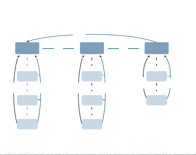
Regatta
[MODE]
TIME
[SELECT]
>
DAILY
ALARMS
[SELECT]
>
[SELECT]
COUNTDOWN
TIMER
[SELECT]
>
DUAL TIME
[MODE]
[MODE]
>
CHRONOGRAPH
[SELECT]
CHRONO
MEMORY
[SELECT]
[SELECT]
[SELECT]
MEMORY
>
>
SAIL
TIMER
>
SAIL
[MODE]
[MODE]
>
[SELECT]
COMPASS
[SELECT]
>
DECLINATION
ADJUSTMENT
[SELECT]
>
COMPASS
CALIBRATION
[MODE]
Page 3
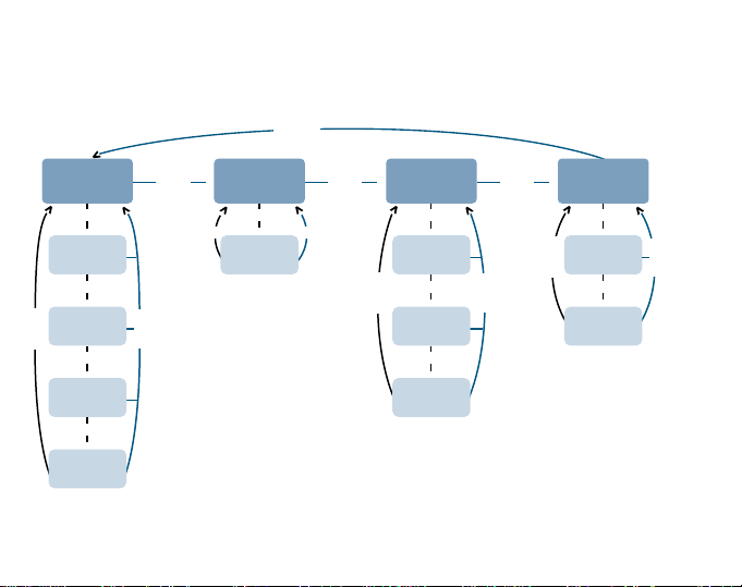
Mariner, Yachtsman
[MODE]
TIME
[SELECT]
>
DAILY
ALARMS
[SELECT]
>
STOPWATCH
[SELECT]
[SELECT]
>
COUNTDOWN
TIMER
[SELECT]
>
DUAL TIME
[MODE]
[MODE]
>
SAILING TIMER
[SELECT]
[SELECT]
>
MEMORY
[MODE]
[MODE]
>
BAROMETER
[SELECT]
DIFFERENCE
MEASUREMENT
[SELECT]
[SELECT]
4 DAY
MEMORY
[SELECT]
SEA LEVEL
PRESSURE
[MODE]
>
COMPASS
>
>
[MODE]
[SELECT]
>
DECLINATION
ADJUSTMENT
[SELECT]
[SELECT]
>
COMPASS
CALIBRATION
[MODE]
>
Page 4
1. 2.
4.3.
8.7.6.5.
10.9.
11.
12.
Page 5
13. 14.
16.15.
20.19.18.17.
22.21.
24.23.
Page 6
25. 26.
28.27.
32.31.30.29.
33.
34.
36.35.
Page 7

37. 38. 40.39.
Page 8

Customer SERVICE Contacts
Suunto USA
Phone 1 (800) 543-9124
Suunto Canada
Phone 1 (800) 776-7770
Web Site www.suuntousa.com
Suunto Europe
Phone +33 3 90 20 74 30
Fax +33 3 90 20 74 40
Web Site www.suuntoeurope.com
Suunto Oy
Phone +358 9 875 870
Fax +358 9 8758 7301
Web Site www.suunto.com
Congratulations, your newly purchased Wristop Computer is designed to provide years of enjoyment in whatever
outdoor activities you engage.
Along with this product you will find a Warranty card, this User s Guide, and a full service support team to give
you the results you need anytime, anywhere, quickly and professionally.
We wish you many unforgettable moments with your new Wristop Computer!
1
EN
Page 9

TABLE OF CONTENTS
CHAPTER 1 INTRODUCTION .......................................................... 5
1.1 KEY FUNCTIONS (MODES) ......................................................................................... 5
1.1.1 Backlight Features ........................................................................................... 5
1.1.2 Water Resistance ............................................................................................ 5
1.2 BUTTON FUNCTIONS ................................................................................................... 5
1.2.1 The [Mode] Button ........................................................................................... 5
1.2.2 The [+] Button .................................................................................................. 6
1.2.3 The [-] Button ................................................................................................... 6
1.2.4 The [Select] Button .......................................................................................... 6
1.3 LCD DISPLAY .................................................................................................................6
1.4 MEASUREMENTS AND UNITS .................................................................................... 8
1.4.1 Selecting the Units of Measurement .............................................................. 8
1.5 PRESSURE SENSOR CALIBRATION .......................................................................... 9
1.6 CARE AND MAINTENANCE .......................................................................................... 9
1.6.1 Battery Replacement ....................................................................................... 9
CHAPTER 2
2.1 SAILING TIMER MEMORY SUB MODE ..................................................................... 12
CHAPTER 3 CHRONOGRAPH MODE (REGATTA) .......................... 13
3.1 HOW TO USE THE CHRONOGRAPH ........................................................................ 13
3.2 HOW TO VIEW THE CHRONOGRAPH MEMORY .................................................... 14
3.3 SAIL TIMER FUNCTION .............................................................................................. 15
3.4 SAIL TIMER MEMORY FUNCTION ............................................................................ 16
CHAPTER 4 TIME MODE ............................................................... 17
SAILING TIMER MODE (MARINER ANDYACHTSMAN)
2
11
Page 10

4.1 HOW TO SET THE TIME ............................................................................................. 18
4.2 DAILY ALARM SUB MODE .......................................................................................... 19
4.2.1 How to Set the Daily Alarms .......................................................................... 19
4.3 STOPWATCH SUB MODE .......................................................................................... 20
4.3.1 How to Use the Stopwatch ............................................................................ 20
4.4 COUNTDOWN TIMER SUB MODE ............................................................................ 21
4.4.1 How to Set the Countdown Timer ................................................................. 22
4.4.2 How to Start the Countdown Timer ............................................................... 22
4.5 DUAL TIME SUB MODE .............................................................................................. 22
4.5.1 Setting the Dual Time Function ..................................................................... 23
CHAPTER 5 BAROMETER MODE (MARINER AND YACHTSMAN) 23
5.1 PRESSURE DIFFERENCE MEASUREMENT SUB MODE ....................................... 24
5.1.1 How to Start the Pressure Difference Measurement .................................... 25
5.2 4-DAY MEMORY SUB MODE ...................................................................................... 25
5.3 SEA LEVEL PRESSURE SUB MODE ......................................................................... 26
5.3.1 Setting the Sea Level Pressure .................................................................... 26
5.4 BAROMETRIC TREND INDICATOR ........................................................................... 27
CHAPTER 6 COMPASS MODE ....................................................... 28
6.1 BEARING TRACKING SUB MODE ............................................................................. 29
6.2 DECLINATION ADJUSTMENT SUB MODE ............................................................... 29
6.2.1 Setting the Local Declination ......................................................................... 30
6.3 CALIBRATING THE COMPASS .................................................................................. 30
CHAPTER 7 FREQUENTLY ASKED QUESTIONS .......................... 31
7.1 GENERAL .....................................................................................................................31
7.1.1 Is the Wristop Computer waterproof? ........................................................... 31
7.1.2 How long will the battery last? ....................................................................... 31
3
Page 11

7.1.3 What do the segments on the circumference mean? ................................... 31
7.1.4 Why do the segments on the circumference go to the left
(counterclockwise)? ....................................................................................... 32
7.1.5 Why is there a symbol above the mode indicator bar and what does
7.2 TIME .............................................................................................................................. 32
7.3 BAROMETER ............................................................................................................... 33
7.4 COMPASS .................................................................................................................... 34
it mean? ......................................................................................................... 32
7.2.1 Why do the segments on the circumference increase and decrease
when I am in the Time mode? ....................................................................... 32
7.2.2 What is the longest time I can set in the timer? ............................................ 33
7.3.1 What is the little box on the top left of the display? ...................................... 33
7.3.2 Does the Wristop Computer show future trends in weather conditions? ..... 33
7.3.3 What does absolute pressure and relative pressure mean? ................... 33
7.3.4 Is the Wristop Computer temperature compensated? .................................. 33
7.4.1 What is the purpose of the rotating outer bezel? .......................................... 34
7.4.2 Where do I find the correct declination for my area so I can set
my Wristop Computer? .................................................................................. 34
8. ABBREVIATIONS ...................................................................... 34
9. SPARE PARTS AVAILABLE ....................................................... 34
10. COPYRIGHT AND TRADEMARK NOTICE ................................ 35
11. CE COMPLIANCE ..................................................................... 35
12. LIMITS OF LIABILITY AND ISO 9001 COMPLIANCE .............. 35
4
Page 12

CHAPTER 1 INTRODUCTION
1.1 MAIN FUNCTIONS (MODES)
The Mariner/Yachtsman features the following functions: sailing timer, barometer, compass and watch. These
are identified as sail mode [SAIL], barometer mode [BARO], compass mode [COMP] and time mode [TIME] in
this manual and also on the display of the instrument.
The Regatta features the following functions: compass, chronograph and watch. These are identified as compass
mode [COMP]. chronograph mode [CHR] and time mode [TIME].
1.1.1 Backlight Features
The Wristop Computer has an electroluminescent backlight. This is initiated by pressing and holding the [Mode]
button in for 2 seconds. The backlight will remain on for 5 seconds. Pressing the [Mode] button during this time
will restart the 5 second period, continuing the backlight feature.
1.1.2 Water Resistance
The Wristop Computer is waterproof to a depth of 30m/100ft.
Note: The Wristop Computer models are not dive instruments. Buttons should not be operated (put to use)
while under water.
1.2 BUTTON FUNCTIONS
Four buttons are used to operate the Wristop Computer: [Mode], [+] (ON/OFF), [-] (Fast Bearing), and [Select].
1.2.1 The [Mode] Button
Is located on the top right of the Wristop Computer.
In the main mode level, pressing the [Mode] button allows the user to select or move from one mode or
function to the next (TIME, SAIL, BARO, COMP).
In the sub mode level, pressing the [Mode] button returns the user to the main mode level.
In the setup process, pressing the [Mode] button accepts the changes or preferences. Pressing the button
again will return the user to the main mode level.
5
Page 13

Pressing the button for 2 seconds activates the backlight feature.
1.2.2 The [+] Button
Is located on the bottom right of the Wristop Computer.
In the setup process, pressing the [+] button changes or scrolls the value upward.
In the timing functions, this button can act as a start/stop (or On/Off) button.
1.2.3 The [-] Button
Is located on the bottom left of the Wristop Computer.
In the setup process, pressing the [-] button changes or scrolls the value downward.
This button is also known as the Fast Bearing button. Pressing the [-] button in any of the main modes
(except in Sailing Timer) will quickly display the compass mode, showing either the normal compass or
bearing tracking feature (depending on what display has been chosen in the compass mode).
1.2.4 The [Select] Button
Is located on the top left of the Wristop Computer.
In the main mode level, pressing the [Select] button allows the user to enter into the sub modes of the
particular function or return to the main mode the user is in.
In the main mode or sub mode, pressing and holding the [Select] button in for more than 2 seconds allows
the user to enter the setup process.
In the setup process, the [Select] button allows the user to move between settable units or values and
determine preferences.
1.3 LCD DISPLAY
The display is designed to offer maximum clarity and simplicity to the user.
The display is divided into several regions or areas.
The Outer Circumference encompasses the outer boundary of the LCD display.
A Barometric Trend Indicator provides a quick reference for forecasting weather conditions.
6
Page 14
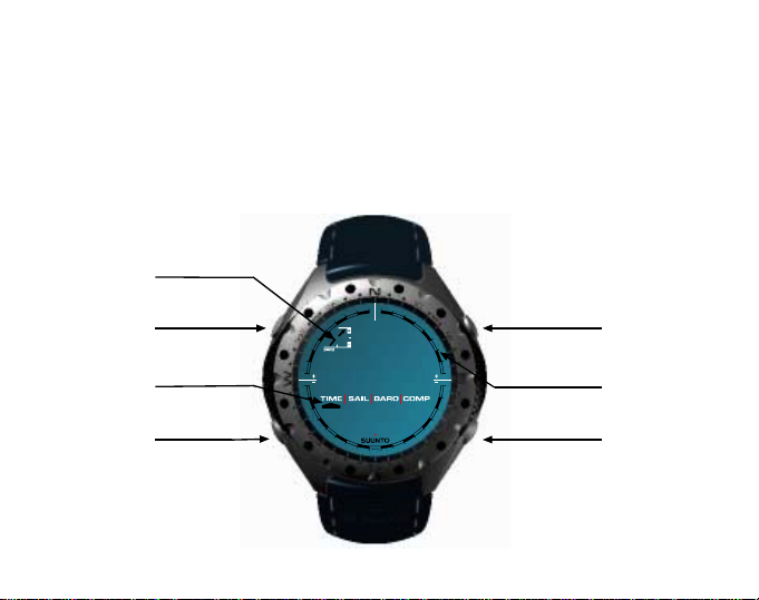
Field 1 displays values either numbers or text depending on the mode or sub mode the user is in.
Field 2 displays large numbers and/or related unit of measure of the function.
A Mode Indictor Bar displays the main modes (functions) of the Wristop Computer (a triangle arrow located
just below the bar indicates the mode the user is viewing).
Field 3 displaying either numbers and/or text.
%DURPHWHU
7UH QG
,QGLFDWRU
6(/(&7
%87721
0RGH
,QGLFDWRU
Field 1
Field 2
02'(
%87721
2XWHU
&LUFXPIHUHQFH
%87721
Field 3
7
%87721
Page 15

1.4 MEASUREMENTS AND UNITS
The Wristop Computer supplies two units of measure: metric or imperial.
Metric Unit of Measure Imperial Unit of Measure
°C °F
mbar inHg
mft
1.4.1 Selecting the Units of Measurement
To change the unit of measure displayed:
1. Check the mode indicator. If the mode arrow is not on TIME, PRESS the [Mode] button until the arrow is
directly below TIME on the Mode Indicator Bar.
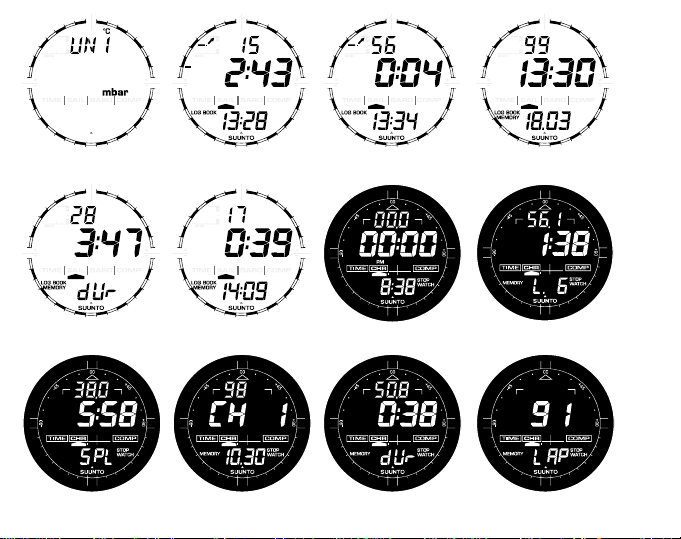
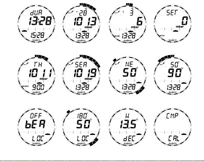
2. PRESS the [Mode] and [Select] buttons simultaneously and hold in for 3 seconds. Field 1 will display SET
momentarily and then display UNI (Fig. 1).
WARNING: If the user presses the [Select] button (and does not hold for 2 seconds) while in the UNI setting
mode, the user will be in the Pressure Sensor Calibration. Refer to the next section for details.
3. PRESS the [Select] button and hold in for 2 seconds. Located to the right in Field 2, mbar or inHg will
begin to flash.
4. PRESS the [+] button to toggle between mbar and inHg.
5. At the unit of measure desired, PRESS the [Select] button to move to the next unit. Located at the top right
in Field 1, °C or °F will begin to flash.
6.PRESS the [+] button to toggle between °C and °F.
7. At the unit of measure desired, PRESS the [Select] button to move to the next unit. Located to the right in
m
Field 2,
8. PRESS the [+] button to toggle between m and ft
9. At the unit of measure desired, PRESS the [Mode] button to accept the changes. PRESS the [Mode] button
again to return to the main time mode.
ft
or
will begin to flash.
8
Page 16

Note: If the user does not press any button for 1 minute in the setup mode, the display will automatically exit
setup.
Selecting the units of measurement is complete.
1.5 PRESSURE SENSOR CALIBRATION
WARNING: This is a FACTORY CALIBRATION SETTING. Do not enter this mode.
If you enter this mode in error, exit immediately by pressing the [MODE] button to return to the UNI setting
mode. Normally there is no need to alter the calibration.
If the Pressure Setting Calibration has been altered, you can return the factory setting. Proceed as follows: In
the calibration setting mode, scroll the barometric pressure value up or down until text dEF appears. This is
the factory setting. Then exit by pressing [MODE].
1.6 CARE AND MAINTENANCE
Perform only the detailed processes discussed in this manual. Do not perform any other service to the Wristop
Computer or attempt to open the case or remove the buttons or the bezel.
Protect your Wristop Computer from shocks, extreme heat and prolonged exposure to direct sunlight. If not in
use, your Wristop Computer should be stored in a clean, dry environment at room temperature.
The Wristop Computer can be wiped clean with a lightly moistened (warm water) cloth. Applying a mild soap to
the area can clean stubborn stains or marks.
Avoid exposing the Wristop Computer to strong chemicals like gasoline, cleaning solvents, acetone, alcohol,
adhesives, and paint, as they will damage the units seals, case and finish.
Never attempt to take the Wristop Computer apart or service it yourself. Make sure the area around the sensors
(backside of the instrument) is kept free of dirt and sand. Never insert any objects into the sensor openings of
the Wristop Computer.
1.6.1 Battery Replacement
The Wristop Computer operates on a three-volt lithium cell Type: CR 2430. The maximum life expectancy is
approximately 12-18 months.
9
Page 17

A low battery-warning indicator is activated when 5-15 percent of the battery capacity is still available. When
this occurs we recommend replacement of the battery.
Extreme cold weather will activate the low battery-warning indicator. Though the indicator is activated, the
battery may not need to be replaced due to this condition. In temperatures above 10°C (50°F) and the low
battery warning indicator is activated, the battery will need to be replaced.
Note: Heavy use of the electroluminescent backlight, and compass will significantly reduce the life of the battery.
To replace the battery:
1. turn the Wristop Computer to view the backside;
2. insert a coin in the coin slot located on the battery compartment cover;
3. turn the coin counterclockwise to the open position marked on the back of the case;
4. remove the battery compartment cover;
5. remove the old cell from the battery compartment and ensure the O-ring and all surfaces are clean and dry.
Do not stretch the O-ring.
6. place the new cell into the battery compartment (negative side down, positive side up);
7. ensure the O-ring is in place to keep the Wristop Computer waterproof and place the battery compartment
cover back onto the backside of the Wristop Computer;
8. insert a coin back into the coin slot; and
9. turn the coin clockwise to the close position marked on the back of the case.
Note: Battery replacement should be performed with extreme care so as to ensure the Wristop Computer
continues to remain waterproof. It is the operators responsibility to take due care to ensure the Wristop Computer
remains waterproof.
After every battery replacement, it is necessary to calibrate the magnetic sensor. Details on performing this
process are found in Calibrating the Compass section of this manual.
10
Page 18

CHAPTER 2 SAILING TIMER MODE (MARINER AND
YACHTSMAN)
To view Sailing Timer:
Check the Mode Indicator Bar. If the mode arrow is not on SAIL, PRESS the [Mode] button until the arrow is
directly below SAIL on the bar.
In the Sail mode (Fig. 2.):
Field 1 the selected time to be counted down in minutes, maximum 120 minutes;
Field 2 the time to be counted down in minutes and seconds; and
Field 3 the current time and the text log book to the left of the current time.
To set the count down, PRESS the [-] button, the selection will begin with 120 minutes. It is adjustable in 10minute increments, from 120 to 60 minutes, in 5-minute increments, from 60 to 15 minutes, and from 15 minutes
to 0 by the minute. Continue pressing the [-] button until the desired minute is achieved. The selected time is
stored in Field 1.
To begin the count down, PRESS the [+] button.
During the count down the timer will activate audible signals.
Interval Audible signal
Every full minute Short double beep
Every 10 seconds during the last minute Short double beep
Every second during the last ten seconds Short single beep
At the completion of the count down Long single beep
When the time to count down has been reached, a stopwatch will automatically start running (Fig. 3). The range
of the stopwatch is 120: 00,00.
Field 1 displays the seconds and tenths of seconds of the event;
Field 2 displays the hours and minutes of the event; and
Field 3 displays the current time and the text logbook to the left of the current time.
11
Page 19

During this activity when the stopwatch is running, the [-] button can be used to store up to 50 split times (way
point times) to be viewed after the race has been completed. The split time (way point time) will be displayed for
10 seconds after pushing the [-] button.
The stopwatch is stopped by pressing the [+] button twice within two seconds. This will eliminate accidental
stops of the stopwatch. The finish time is also stored in the memory. After the stopwatch has been stopped, the
[-] button returns the user to the countdown display.
PRESS the [Mode] button once to return to the Sailing Timer main mode.
2.1 SAILING TIMER MEMORY SUB MODE
In the Sail mode, PRESS the [Select] button once.
In the first display (Fig. 4):
Field 1 shows the year of race;
Field 2 shows the starting time of the race; and
Field 3 shows starting date of race and the text log book and memory to the left.
PRESS the [+] button to view the second display.
In the second display (Fig. 5):
Field 1 shows the seconds and tenths of seconds of the timed event;
Field 2 shows the hours and minutes of the event; and
Field 3 shows the text dUr (dUr = duration).
PRESS the [+] button to display the stored split times (way point times) (Fig. 6):
Field 1 shows the seconds and tenths of seconds of the split time;
Field 2 shows the hours and minutes of the split time; and
Field 3 shows the actual time when the split time was taken. If you stop to view this display the date as well
as the year of the split moment will start alternating with the time.
PRESS the [+] and [-] buttons to scroll through the split times.
PRESS the [Select] button to exit and return to the main mode.
12
Page 20

Note: Only one race can be stored in the memory. As soon as the count down function is restarted, the information
from the previous race will be erased from the memory.
CHAPTER 3 CHRONOGRAPH MODE (REGATTA)
The chronograph mode is able to:
measure and store 1-99 split and lap times for up to 99 runs; and
obtain a maximum range of one run (timing event) up to 23 hours 59 minutes and 59.9 seconds. Upon
exceeding this range the Regatta will activate an audible sound to indicate the maximum range has been
reached and the timing process has stopped.
To view Chronograph mode:
Check the Mode Indicator Bar. If the mode arrow is not on CHR, PRESS the [Mode] button until the arrow is
directly below CHR on the bar.
In the Chronograph mode (Fig. 7):
Field 1 displays the seconds and tenths of seconds of the timer.
Field 2 displays the timer showing the hours and minutes.
Field 3 displays the current time and to the right the text Stopwatch.
Note: If the stopwatch function is on and the user is in another mode other than the main chronograph mode,
the text Stopwatch flashes to remind the user this function is activated.
3.1 HOW TO USE THE CHRONOGRAPH
In the chronograph mode:
1. PRESS the [+] button to start the stopwatch.
2. PRESS the [-] button to store the lap time and split time in memory.
Lap and split times are displayed as follows:
In Field 1 the lap time is shown for the latest lap shown in Field 3 L # (# = lap number) (Fig. 8). The lap time is
displayed for five seconds before the measured split time is displayed.
13
Page 21

The split time is indicated by the abbreviation SPL (SPL = split) in Field 3 displaying for five seconds before it
returns to showing the running time (Fig. 9).
Note: The user can continuously press the [-] button during this activity and can record and display new lap and
split times up to 99 times.
3. PRESS the [+] button to stop the stopwatch.
4. PRESS the [-] button to reset the stopwatch to zero once the stopwatch has stopped.
Note: If the user decides to go to a different mode while utilizing the chronograph feature, the chronograph/
stopwatch will continue to run in the background.
The timing of another event cannot start until the stopwatch has been zeroed after the first timing. The zeroing
is done by pushing the [-] button.
3.2 HOW TO VIEW THE CHRONOGRAPH MEMORY
In the Chronograph mode, PRESS the [Select] button once. This sub mode features three screens. These
screens automatically rotate displaying a summary of information of the most recent completed timed event in
intervals of 4 seconds.
In the first display (Fig. 10):
Field 1 displays the year;
Field 2 displays the event number CH #; and
Field 3 displays date of the timed event
The user can PRESS the [-] button to scroll down to view previous timed events captured and then PRESS [+]
button to scroll up to the most recent completed timed event.
The second display shows duration of run/timing event on the bottom row (Fig. 11):
Field 1 displays the seconds and tenths of seconds of the timed event;
Field 2 displays the total time of the event in hours and minutes; and
Field 3 displays the text dUr (dUr = duration).
The third display shows the total number of laps stored into memory (Fig. 12):
14
Page 22

Field 2 displays the total number of laps stored; and
Field 3 displays the text LAP.
Viewing the timed events individual lap and split times
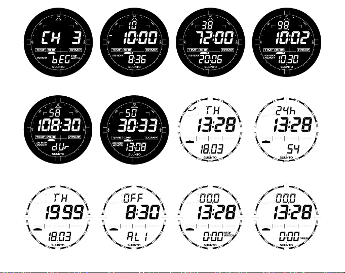
1. PRESS and hold the [Select] button for 2 seconds (Fig. 13):
Field 2 displays the event number CH # the user will be viewing; and
Field 3 displays the text bEG (begin).
2. PRESS the [+] button to view the lap and split time which is in chronological order beginning with lap1.
Field 1 displays the seconds and tenths of seconds of the lap or split time;
Field 2 displays the hours and minutes of the lap or split time; and
Field 3 displays the text L # or SPL (SPL = split time).
follow automatically.
3. PRESS the [+] button to continue viewing the reminder of lap and split times recorded. When the last lap
and split times have been viewed, the display will show in Field 2 CH #; and in Field 3 the text End
(indicating the end of this activity).
4. PRESS the [Mode] button once to exit and return to the chronograph memory sub mode.
The lap time will be viewed first the split time will
3.3 SAIL TIMER FUNCTION
In the Chronograph mode, PRESS the [Select] button two times.
The display shows in (Fig. 14):
Field 1 the selected time to be counted down in minutes, maximum 10 minutes;
Field 2 the time to be counted down in minutes and seconds; and
Field 3 the current time and the text logbook to the left of the current time.
To set the count down, PRESS the [-] button, the selection will begin with 10 minutes. Continue pressing
the [-] button until the desired minute is achieved. The selected time is stored in Field 1.
To begin the count down, PRESS the [+] button.
During the count down the timer will activate audible signals.
15
Page 23

Interval Audible signal
Every full minute Short double beep
Every 10 seconds during the last minute Short double beep
Every second during the last ten seconds Short single beep
At the completion of the count down Long single beep
When the time to count down has been reached, a stopwatch will automatically start running (Fig. 15). The
range of the stopwatch is 119:59,59.
Field 1 displays the seconds and tenths of seconds of the event;
Field 2 displays the hours and minutes of the event; and
Field 3 displays the current time and the text logbook to the left of the current time.
During this activity when the stopwatch is running, the [-] button can be used to store up to 50 split times
(waypoints) to be viewed after the race has been completed. The split time (waypoint time) will be displayed for
10 seconds after pushing the [-] button.
The stopwatch is stopped by pressing the [+] button twice within two seconds. This will eliminate accidental
stops of the stopwatch. The finish time is also stored in the memory. After the stopwatch has been stopped, the
[-] button returns the user to the countdown display.
PRESS the [Mode] button once to return to the chronograph main mode.
3.4 SAIL TIMER MEMORY FUNCTION
In the Chronograph mode, PRESS the [Select] button three times.
In the first display (Fig. 16):
Field 1 shows the year of race;
Field 2 shows the starting time of the race; and
Field 3 shows starting date of race (month and day) and the text logbook and memory to the left.
PRESS the [+] button to view the second display.
16
Page 24

In the second display (Fig. 17):
Field 1 shows the seconds and tenths of seconds of the timed event;
Field 2 shows the hours and minutes of the event; and
Field 3 shows the text dUr (dUr = duration).
PRESS the [+] button to display the stored split times (waypoint times) (Fig. 18):
Field 1 shows the seconds and tenths of seconds of the split time;
Field 2 shows the hours and minutes of the split time; and
Field 3 shows the starting time of the race. If you stop to view this display, start date of the race as well as the
year will start alternating with the start time on the bottom row.
PRESS the [+] and [-] buttons to scroll through the split times.
PRESS the [Select] button to exit and return to the main mode.
Note: Only one race can be stored in the memory. As soon as the count down function is restarted, the information
from the previous race will be erased from the memory.
CHAPTER 4 TIME MODE
The Time mode provides the user with:
an adjustable 24/12 hour clock display;
a calendar pre-programmed to the year 2089;
three daily alarms;
stopwatch;
countdown timer; and
a dual time operation.
To view and use the Time mode function:
Check the Mode Indicator arrow. If the mode arrow is not on TIME, PRESS the [Mode] button until the arrow is
directly below TIME.
17
Page 25

In the TIME mode (Fig. 19):
Field 1 displays the day of the week.
Field 2 displays the current time.
Field 3 displays the date (month/day if the 12-hour clock has been chosen; day/month if the 24-hour clock
has been chosen).
The Outer Circumference graphically displays time in seconds.
The TIME mode and all sub modes can be adjusted through the set up program of the Wristop Computer.
4.1 HOW TO SET THE TIME
To set the Time:
1. PRESS the [Select] button and hold in for 2 seconds. Located in Field 3, the seconds will begin to flash
(Fig. 20).
2. PRESS the [+] button to scroll the seconds upward or PRESS the [-] button to reset the seconds to zero.
3. At the seconds desired, PRESS the [Select] button to move to the next setting. Located on right of Field 2,
the minutes will begin to flash.
4. PRESS the [+] button to scroll the minutes upward or PRESS the [-] button to scroll the minutes downward.
5. At the minutes desired, PRESS the [Select] button to move to the next setting. Located in the center of Field
2, the hour will begin to flash.
6. PRESS the [+] button to scroll the hour upward or PRESS the [-] button to scroll the hour downward.
7. At the hour desired, PRESS the [Select] button to move to the next setting. Located in Field 1, the 24 or 12
hour clock setting will begin to flash.
8. PRESS either the [+] or the [-] button to toggle between the 24hr and 12hr.
Note: if the 12 hour clock is chosen either AM/PM will appear below the hour in Field 2.
9. At the clock setting desired, PRESS the [Select] button to move to the next setting. Located in the center of
Field 2, the year will begin to flash (Fig. 21).
10. PRESS the [+] button to scroll the year upward or PRESS the [-] button to scroll the year downward.
18
Page 26

11. At the year desired, PRESS the [Select] button to move to the next setting. Located in the center of Field 3,
the month represented by a number will begin to flash.
12. PRESS the [+] button to scroll the month upward or PRESS the [-] button to scroll the month downward.
13. At the month desired, PRESS the [Select] button to move to the next setting. Located to the right of Field 3,
the day will begin to flash.
14. PRESS the [+] button to scroll the day upward or PRESS the [-] button to scroll the date downward.
Note: Once the user has determined the year, month and day, the Wristop Computer will supply the day of the
week in Field 1.
Note: If the 12-hour clock is chosen, the date will be displayed as month/day. If the 24-hour clock is chosen, the
date will be displayed day/month.
15.At the desired day, PRESS the [Mode] button to accept the changes and return to the main mode.
Note: If the user does not press any button for 1 minute in the setup mode, the display will automatically exit
setup.
Setting the time is now complete.
4.2 DAILY ALARM SUB MODE
The Wristop Computer allows the user to select and enter settings for up to three alarms.
In the TIME mode, PRESS the [Select] button once to enter this sub mode.
In the Daily Alarm sub mode (Fig. 22):
Field 1 displays ON or OFF (the activation status of a particular alarm),
Field 2 displays the time of a particular alarm, and
Field 3 displays the alarm (1, 2, or 3) the user is viewing.
Pressing the [+] or the [-] button will toggle between the alarms 1, 2, or 3 to view the settings for each alarm.
4.2.1 How to Set the Daily Alar ms
1. PRESS the [+] or the [-] button to select the desired alarm to be set (1, 2, or 3).
19
Page 27

2. PRESS the [Select] button and hold in for 2 seconds. Located in Field 1, the ON or OFF will begin to
flash.
3. PRESS either the [+] or the [-] button to toggle between ON and OFF.
4. At the setting desired, PRESS the [Select] button to move to the next setting. Located in the center of Field
2, the hour will begin to flash.
5. PRESS the [+] button to scroll the hour upward or PRESS the [-] button to scroll the hour downward.
6. At the hour desired, PRESS the [Select] button to move to the next setting. Located on the right of Field 2,
the minutes will begin to flash.
7. PRESS the [+] button to scroll the minutes upward or PRESS the [-] button to scroll the minutes downward.
8. At the minutes desired, PRESS the [Mode] button to accept the changes and exit the setup program. A small
bell will appear at the bottom left side in Field 2 to signify an alarm has been activated.
The Alarm setup is complete. To activate up to three alarms, please repeat steps 1-8 for the selected alarm (1,
2, or 3).
4.3 STOPWATCH SUB MODE
The Wristop Computer stopwatch sub mode can provide split time measurement and two finish times up to 24
hours. In the TIME mode, PRESS the [Select] button twice to enter this sub mode.
In the Stopwatch sub mode (Fig. 23):
Field 1 displays the seconds and tenths of a second,
Field 2 displays the current time, and
Field 3 displays hours and minutes and to the far right stopwatch.
4.3.1 How to Use the Stopwatch
There are three timing modes the user can employ:
an elapsed time measurement;
a split time measurement; and
a two finish time measurement.
20
Page 28

In the elapsed time mode:
1. PRESS the [+] button to start, stop, and restart the stopwatch.
2. PRESS the [-] button to reset the stopwatch to zero once the stopwatch has stopped.
In the split time mode:
1. PRESS the [+] button to start the stopwatch.
2. PRESS the [-] button once to stop the stopwatch and to display a split time.
3. PRESS the [-] button a second time to release the split time display and resume the stopwatch.
4. PRESS the [+] button to stop the stopwatch.
5. PRESS the [-] button to reset the stopwatch to zero once the stopwatch has stopped.
In the two finish time mode:
1. PRESS the [+] button to start the stopwatch.
2. PRESS the [-] button once to stop the stopwatch to display the finish time of the first person.
3. PRESS the [+] button to stop the stopwatch.
4. PRESS the [-] button a second time to release and display the finish time of the second person.
5. PRESS the [-] button to clear and to reset the stopwatch.
Note: When the stopwatch sub mode is activated, the stopwatch will continue and remain in the background if
the user is in other modes or sub modes. The user can identify the stopwatch is still activated by the flashing
text stopwatch in Field 3.
4.4 COUNTDOWN TIMER SUB MODE
In the TIME mode, PRESS the [Select] button three times to enter this sub mode.
In the countdown timer sub mode (Fig. 24):
Field 1 displays the seconds,
Field 2 displays the current time, and
Field 3 displays the hour and minutes and to the bottom far right the text timer.
21
Page 29

4.4.1 How to Set the Countdown Timer
1. PRESS the [Select] button and hold in for 2 seconds. Located in Field 1, the seconds will begin to flash.
2. PRESS the [+] button to scroll the seconds upward or
PRESS the [-] button to scroll the seconds downward.
3. At the seconds desired, PRESS the [Select] button to move to the next setting. Located on right of Field 3,
the minutes will begin to flash.
4. PRESS the [+] button to scroll the minutes upward or
PRESS the [-] button to scroll the minutes downward.
5. At the minutes desired, PRESS the [Select] button to move to the next setting. Located in the center of Field
3, the hour will begin to flash.
6. PRESS the [+] button to scroll the hour upward or
PRESS the [-] button to scroll the hour downward.
7. At the hour desired, PRESS the [Mode] button to accept the changes and exit the set up program.
The countdown timer setup is complete.
4.4.2 How to Start the Countdown Timer
To start the countdown timer:
1. PRESS the [+] button to start, stop, and restart the timer.
2. PRESS the [-] button to reset the timer to zero once the timer has stopped.
Note: When the countdown timer is activated, the countdown timer will continue and remain in the background
if the user is in other modes or sub modes. The user can identify the countdown timer still activated by the
flashing text timer in Field 3.
4.5 DUAL TIME SUB MODE
In the TIME mode, PRESS the [Select] button four times to enter this sub mode.
In the dual time sub mode (Fig. 25):
22
Page 30

Field 1 displays dUA indicating dual time,
Field 2 displays the current time, and
Field 3 displays the dual time (e.g. your home time).
The user can display the seconds while in this sub mode by pressing the [+] button, in Field 3 the seconds will
appear for 10 seconds. Afterwards the display returns to showing the dual time.
4.5.1 Setting the Dual Time Function
In the dual time sub mode:
1. PRESS the [Select] button and hold in for 2 seconds. Located in Field 3, the hours will begin to flash.
2. PRESS the [+] button to scroll the hours upward or PRESS the [-] button to scroll the hours downward.
3. At the hour desired, PRESS the [Select] button to move to the next setting. Located in Field 3 to the right of
the hour value, the minutes will begin to flash.
4. PRESS the [+] button to scroll the minutes upward or PRESS the [-] button to scroll the minutes downward.
5. At the minutes desired, PRESS the [Mode] button to accept the changes and exit the setup program.
The dual time setup is complete.
The dual time stays the same, even though the time in the main time mode is adjusted. For example, if you set
the dual time to show your home time, your home time will always be displayed in this sub mode even though
you travel to a different time zone and adjust the time in the main time mode.
Note: The dual time sub mode is completely independent and does not effect the alarms or the memory functions.
These are dependent on the current local time.
CHAPTER 5 BAROMETER MODE (MARINER AND
YACHTSMAN)
The Barometer mode provides the user with:
an adjustable unit of measure mbar or inHg; mbar range 300 to 1 100 mbar, inHg range 8.90 to 32.40;
a resolution of 1 mbar or 0.05 inHg;
23
Page 31

a one hour interval measuring to estimate barometric trend;
· a difference measurement function;
an automatic 4-day memory of atmospheric pressure for the last 6 hours in 1-hour intervals, thereafter, in 6-
hour intervals;
temperature compensation (temperature does not effect the pressure within the specified temperature range)
a temperature range -20° to 60°C or -5° to 140°F; and
a temperature resolution of 1° C or F.
Note: Body heat will effect temperature when the Wristop Computer is worn on the wrist. To achieve an accurate
reading remove the Wristop Computer from the wrist and allow at least 15 minutes before reading the temperature.
If youve been in the barometer mode for more than 15 minutes with no rate of vertical movement, you should
allow 1 hour for the Wristop Computer to adjust the temperature. To acquire a quicker up-date of the temperature,
press the [Mode] button 4 times to re-enter the mode.
To view and use the Barometer mode:
Check the Mode Indicator Bar. If the mode arrow is not on BARO, PRESS the [Mode] button until the arrow is
directly below BARO on the bar.
In the Barometer mode (Fig. 26):
Field 1 displays the current temperature.
Field 2 displays the current absolute atmospheric pressure.
Field 3 displays the current time.
The Outer Circumference graphically displays the atmospheric pressure over 100 millibars or 1 inHg where
one complete circle is equivalent to 100 mbar/1 inHg, depending on the unit of measure chosen.
Note: The absolute pressure is the actual pressure in any location at any given time. Where as, sea level
pressure is the corresponding pressure at sea level.
5.1 PRESSURE DIFFERENCE MEASUREMENT SUB MODE
In the Barometer mode, PRESS the [Select] button once to enter this sub mode.
24
Page 32

In the Pressure Difference Measurement sub mode (Fig. 27):
Field 1 displays the change in temperature.
Field 2 displays the change in atmospheric pressure.
Field 3 displays the current time; to the left of the time is the text differ.
The Outer Circumference graphically displays the change in pressure where one full circle equals 100 mbars
or 1 inHg.
This sub mode does continue in the background and allows the user to move to other modes and at the users
convenience can return to this sub mode to show the current reading.
5.1.1 How to Start the Pressure Difference Measurement
1. PRESS the [Select] button and hold in for 2 seconds. Located in Field 1 is the text SET; located in Field 2,
zero will begin to flash (Fig. 28).
2. PRESS the [Mode] button to accept the flashing zero and start the difference measurement.
If the user does not desire to begin the difference measurement, PRESS either the [+] or the [-] button to toggle
to the current barometric pressure reading, then PRESS the [Mode] button to exit the setup program.
Note: If the user does not press any button for 1 minute in the setup mode, the display will automatically exit
setup.
5.2 4-DAY MEMORY SUB MODE
In the Barometer mode, PRESS the [Select] button twice to enter this sub mode. This sub mode allows the user
to follow changes in pressure that will assist forecasting changes in weather condition (i.e. storms).
In the 4-day memory sub mode (Fig. 29):
Field 1 displays the day of the week the user is in;
Field 2 displays the atmospheric pressure; and
Field 3 displays the time and to the left the text memory.
The Outer Circumference graphically displays the atmospheric pressure where one full circle equals
100 mbars or 1 inHg.
25
Page 33

To view the information compiled in the 4-day memory:
PRESS the [-] button to scroll back down in increments of one hour for the first six hours, after that increments
are 6 hours.
PRESS the [+] button to scroll back up.
Note: Replacing the battery will not erase this information.
5.3 SEA LEVEL PRESSURE SUB MODE
Sea level pressure is pressure relative to sea level where as the pressure read in the main barometric display
is absolute pressure in the current location.
In the Barometer mode, PRESS the [Select] button three times to enter this sub mode.
In the sea level pressure sub mode (Fig. 30):
Field 1 displays the text SEA;
Field 2 displays the current sea level pressure; and
Field 3 displays the current time.
5.3.1 Setting the Sea Level Pressure
To set the sea level pressure you have two choices either give the current sea level pressure or give the exact
altitude of the location (e.g. lake).
1. PRESS the [Select] button and hold in for 2 seconds. Located in Field 2, the current sea level pressure will
begin to flash.
2. PRESS the [+] button to scroll the pressure upward or
PRESS the [-] button to scroll the pressure downward.
3. At the desired pressure, PRESS the [Mode] button to accept the changes and return to the main mode or if
you want use altitude to set the sea level pressure, PRESS the [Select] button. Located in the field 2 the
current reference altitude will begin to flash.
4. PRESS the [+] button to scroll the altitude upward or
PRESS the [-] button to scroll the altitude downward.
26
Page 34

5. At the desired value, PRESS the [Mode] button to accept the changes and return to the main mode.
Note: Information on the current sea level pressure can be obtained through newspapers, local news and radio
weather reports, the local airport facility or through the Internet under local weather. Information on the altitude
can be found by utilizing a topographical map identifying the current location with the associated altitude marked.
If the user does not press any button for 1 minute in the setup mode, the display will automatically exit setup.
5.4 BAROMETRIC TREND INDICATOR
Located on the top left corner of the LCD display resides the Barometric Trend Indicator. This feature is always
displayed in all main modes providing the user a continual quick reference to analyze upcoming weather
conditions.
The Barometric trend is comprised of two lines forming an arrow. Each line represents a 3-hour period. The
right line represents the last 3 hours. The left line represents 3 hours prior to the last 3 hours. The line can
indicate 9 different patterns in the barometric trend.
Situation 6-3 hours ago Situation last 3 hours
Dropped heavy (>2 mbars/3hours) Dropping heavy (>2 mbars/3hours)
Dropped heavy (>2 mbars/3hours) Remaining stable
Dropped heavy (>2 mbars/3hours) Rising heavy (>2 mbars/3hours)
Remained stable Dropping heavy (>2 mbars/3hours)
Remained stable Remaining stable
Remained stable Rising heavy (>2 mbars/3hours)
Risen heavy (>2 mbars/3hours) Rising heavy (>2 mbars/3hours)
Risen heavy (>2 mbars/3hours) Remaining stable
Risen heavy (>2 mbars/3hours) Dropping heavy (>2 mbars/3hours)
Note: If the user remains at the same elevation, the barometric trend indicator can work as a weather forecasting
tool.
27
Page 35

CHAPTER 6 COMPASS MODE
The compass mode provides the user with:
a cardinal or half cardinal point abbreviation;
bearing degrees;
a North-South arrow;
a bearing track mode showing desired direction and actual bearing;
a rotating bezel;
a resolution of 1° for the bearing, ±5° for North-South direction; and
a declination correction feature.
To view and use the Compass mode:
Check the Mode Indicator Bar. If the mode arrow is not on COMP, PRESS the [Mode] button until the arrow is
directly below COMP on the bar.
In the COMPASS mode (Fig. 31):
Field 1 displays the cardinal or half-cardinal point.
Field 2 displays the bearing in degrees.
Field 3 displays the current time.
The Outer Circumference graphically displays the North-South arrow where one-lit segment shows North
and three-lit segments show South.
The compass display is active for 45 seconds at a time. After this, the compass enters sleep mode and
an ---° indicator appears in the field 2. Reactivate the compass by pressing the [-] button.
The Mariner provides a bubble level for the user to achieve a precise reading within ±3 degrees. The user
centers the liquid bubble to ensure the Wristop Computer position is level and takes a reading.
Note: Compass readings should be performed away from objects possessing sources of magnetism. Avoid
buildings, large metal objects, power lines, loudspeakers, electric motors etc.
Always take bearings in the open air, not inside tents, caves, or other shelters.
28
Page 36

6.1 BEARING TRACKING SUB MODE
The user can select to change from the cardinal point mode to the bearing track mode and utilize the bearing
lock feature in this mode for tracking purposes (Fig. 32).
In the compass main mode:
1. PRESS the [Select] button and hold in for 2 seconds. Located in Field 1, OFF will begin to flash and the
field 2 shows the text bEA (bearing) (Fig. 33).
2. PRESS either the [+] or the [-] button to change the setting between OFF and ON.
3. At the selection desired, PRESS the [Select] button to move to the next setting. Located in Field 2, the actual
bearing in degrees will begin to flash (Fig. 34).
4. Turn the Wristop Computer to the desired direction. Lock the bearing displayed by pressing the [-] button.
5. Adjust the locked bearing, if necessary by pressing the [Select] button and then adjusting the value with the
[+] and [-] buttons.
6. At the desired bearing to track, PRESS the [Mode] button to accept the changes and exit the setup program.
Note: If the user does not press any button for 1 minute in the setup mode, the display will automatically exit
setup.
6.2 DECLINATION ADJUSTMENT SUB MODE
The Wristop Computer allows the user to compensate the difference between true north and magnetic north.
This process is accomplished by adjusting the declination, resulting in the user obtaining correct compass
readings.
In the Compass mode, PRESS the [Select] button once to enter this sub mode.
In the Declination Adjustment sub mode (Fig. 35):
Field 1 displays the declination direction OFF where
OFF = no declination; W = West; E = East.
Field 2 displays declination in degrees.
Field 3 displays the text dEC.
29
Page 37

6.2.1 Setting the Local Declination
1. PRESS the [Select] button and hold in for 2 seconds. Located in Field 1, OFF will begin to flash.
2. PRESS either the [+] or the [-] button to change the declination direction in Field 1.
3. At the direction desired, PRESS the [Select] button to move to the next setting. Located in Field 2, the
degrees will begin to flash.
4. PRESS the [+] button to scroll the degrees upward or
PRESS the [-] button to scroll the degrees downward.
5. At the degrees desired, PRESS the [Mode] button to accept the changes and exit the setup program.
Note: If the user does not press any button for 1 minute in the setup mode, the display will automatically exit
setup.
Local Declination is now set.
6.3 CALIBRATING THE COMPASS
A compass calibration should be done when the Wristop Computer is subject to close proximity of magnetic
sources, extreme cold weather, every time the battery is replaced or suspected that other environmental conditions
have effected the compass readings.
Note: We also recommend calibrating the compass before using the compass the first time and every time
leaving for a hike where the compass will be used.
To begin the calibration:
1. PRESS the [Select] button twice when in the main compass mode. Field 1 displays the text CMP. Field 3
displays the text CAL (Fig. 36).
2. PRESS the [Select] button and hold in for 2 seconds. Located in Field 2, the text PUSH will begin to flash
(Fig. 37).
3. PRESS the [-] button to start calibration.
4. In Field 2, 360° appears and the Outer Circumference displays all segments lit (Fig. 38). When this occurs,
hold the Wristop Computer level and start to slowly turn the device around a full circle in a level position. The
30
Page 38

direction of turning does not matter. The lit segments will be turned off as the turning proceeds. When the
first full circle is completed, the instrument will inform the user within one minute of whether the calibration
was successful displaying the text dOnE in Field 2 (Fig. 39) or if the process needs to be repeated displaying
PUSH and - in Field 2.
Note: The user may need to perform the rotating of the compass more than twice around for the calibration to
be completed.
Note: If the text FAIL appears in Field 2 (Fig. 40), the battery should be removed and put back in before trying
to proceed with the calibration process. The removal of the battery will reset the unit.
5. Once the calibration is successful, PRESS the [Mode] button to accept the process and exit the calibration
mode.
Note: It is important to hold the Wristop Computer level during the calibration process to ensure accuracy.
The compass calibration is complete.
CHAPTER 7 FREQUENTLY ASKED QUESTIONS
7.1 GENERAL
7.1.1 Is the Wristop Computer waterproof?
Yes, it is waterproof to a depth of 30 meters (100 ft). Rain and other normal exposure to water will not effect its
operation. You can swim wearing your Wristop Computer. However, the Wristop Computer is NOT a diving
device.
7.1.2 How long will the battery last?
All users employ the product in different ways. Battery life depends mainly on how much the backlight and the
compass are used. The low-battery warning symbol appears on the display when 5 to 15 percent of battery
capacity remains. This should give the user plenty of time to safely change the battery.
7.1.3 What do the segments on the circumference mean?
In the Barometer mode, one full circle equals 100 mbar or 1 inHg, and the segments indicate the pressure over
31
Page 39

a full hundred mbar or over a full inHg. When using the difference measurement function of the barometer, the
segments indicate the change in atmospheric pressure either to the right if the pressure has risen or to the left
if the pressure has dropped.
In the main Compass mode, the segments indicate the North, i.e. the one segment indicates North and the
three segments point South. If you have set the compass to track a certain bearing, the segments on the
circumference indicate the difference between the direction in which you want to go and your actual bearing.
7.1.4 Why do the segments on the circumference go to the left
(counterclockwise)?
Normally, they always go to the right (clockwise) from the 12-noon position.
You are in the difference measurement mode and your unit is showing a decreasing value. In normal mode, the
segment display increases clockwise, but if you are in a mode that shows you differences, all decreasing
values go counterclockwise from the center position, and all increasing values go clockwise. So, it is minus to
the left (counterclockwise), and plus to the right (clockwise).
7.1.5 Why is there a symbol above the Mode Indicator Bar and
what does it mean?
The symbol indicates that one, two, or three daily alarms are activated.
7.2 TIME
7.2.1 Why do the segments on the circumference increase and
decrease when I am in the Time mode?
The main function of the segments is related to the Compass mode, where a division into 36 segments is
necessary due to the 360-degree scale of a compass. In the Time mode, the segments show the advancement
of seconds. Because the number of seconds differs from the number of degrees, it is impossible for the segments
to be consecutively lit up; they now light up or extinguish, thereby marking the passing of every second.
32
Page 40

7.2.2 What is the longest time I can set in the timer?
The maximum range of the countdown timer is 23 hours 59 minutes and 59 seconds.
7.3 BAROMETER
7.3.1 What is the little box on the top left of the display?
It is the barometric trend indicator that shows the general direction of weather changes. The display is based on
barometer measurements for the last 6 hours.
7.3.2 Does the Wristop Computer show future trends in weather
conditions?
No, the Wristop Computer continually accumulates data on barometric pressure existent within a 3 to 6 hour
window and displays general barometric trends in weather based on the accumulated data.
7.3.3 What does absolute pressure and relative pressure
mean?
Absolute pressure is the actual pressure in any location at any given time. Relative pressure on the other hand
equals the corresponding pressure at sea level for a certain altitude that you are at. For example, if you are at
an altitude of 1,000 m/3,300 ft the absolute pressure normally is around 900 mbar/26.60 inHg. The relative
pressure at sea level would then be around 1,013 mbar/29.90 inHg.
7.3.4 Is the Wristop Computer temperature compensated?
Yes, the Wristop Computer is temperature compensated, which means that for the temperature range specified
(-5 to +140°F/-20 to +60°C), the instrument will show accurate pressure. Within this range, the temperature has
no effect on the atmospheric pressure reading.
Temperature compensation does not, however, mean that the temperature reading isnt at all effected by body
heat. Body heat will affect the temperature reading, and to get the correct temperature reading of the environment
remember to take the Wristop Computer off your wrist and wait about 15 minutes for it to stabilize and show the
correct temperature of the surroundings.
33
Page 41

7.4 COMPASS
7.4.1 What is the purpose of the rotating outer bezel?
The purpose of the rotating bezel is that people can use the instrument as a regular base plate compass if they
want to, and use the bezel to e.g. indicate North when in the bearing tracking mode or leaving the compass
display for another mode.
7.4.2 Where do I find the correct declination for my area so I can
set my Wristop Computer?
Local declination, either E or W, is usually marked on maps with either one-degree or half-degree accuracy.
8. ABBREVIATIONS
dEF - default factory setting of pressure
sensor, corresponds to standard
(1013 mbar or 29,90 inHg) air pressure
at sea level
SNR - sensor (used in pressure sensor
calibration)
bEG - begin
dUR - duration
dUA - dual time
SPL - split time
CMP - compass
bEA - bearing
CAL - calibration
dEC - declination
9. SPARE PARTS AVAILABLE
Battery Replacement Kit (including battery, battery lid and o-ring)
Watch Straps in plastic (Regatta/Mariner) or leather (Yachtsman)
Extension strap in plastic
Bezel (Available only in Suunto Oy during maintenance)
34
Page 42

Suunto Oy provides moderate-priced Wristop Computer service to its customers. Batteries are usually available
in sport and watch shops etc.
10. COPYRIGHT AND TRADEMARK NOTICE
This publication and its contents are proprietary to Suunto Oy and are intended solely for the use of its clients
to obtain knowledge and key information regarding the operation of Wristop Computer.
Its contents shall not be used or distributed for any other purpose and/or otherwise communicated, disclosed or
reproduced without the prior written consent of Suunto Oy.
Suunto, Wristop Computer, Mariner, Regatta, Yachtsman and their logos are all registered or unregistered
trademarks of Suunto Oy. All rights are reserved.
While we have taken great care to ensure that information contained in this documentation is both comprehensive
and accurate, no warranty of accuracy is expressed or implied.
11. CE COMPLIANCE
All Suunto Wristop Computers conform with the required European Union EMC directives 89/336/TEC.
12. LIMITS OF LIABILITY AND ISO 9001 COMPLIANCE
If this product should fail due to defects in materials or workmanship, Suunto Oy will, at its sole option, repair or
replace it with new or rebuilt parts, free of charge, for two (2) years from the date of its purchase. This warranty
is extended only to the original purchaser and only covers failures due to defects in materials and workmanship
that occur during normal use while in the period of the warranty.
It does not cover damage or failures resulting in accident, misuse, neglect, mishandling, alteration or modifications
of the product, or any failure caused by operation of the product outside the scope of its published specifications,
or any causes not covered by this warranty.
There are no express warranties except as listed above.
The client can exercise the right to repair under the warranty by contacting our Customer Service department to
obtain a repair authorization.
35
Page 43

Suunto Oy, Suunto Europe and Suunto USA/Canada shall in no event be liable for any incidental or consequential
damages arising from the use of or inability to use the product. Suunto Oy does not assume any responsibility
for losses or claims by third parties that may arise through the use of this device.
Suuntos Quality Assurance System is certified by Det Norske Veritas to be ISO 9001 compliant in all Suunto
Oys operations (Quality Certificate No. 96-HEL-AQ-220).
36
Page 44

MANUEL DUTILISATION
Services consommateurs
Suunto Europe
tél : +33 3 90 20 74 30
fax : +33 3 90 20 74 40
Site web http://www.suunto-europe.com
Suunto Oy
tél : +358 9 875 870
fax : +358 9 8758 7301
Site web http://www.suunto.com
Félicitations, votre nouvel ordinateur de plein air Suunto a été conçu pour vous assurer de longues années de
bons et loyaux services dans la pratique de vos activités de plein air, quelles quelles soient.
Cet instrument est accompagné dune carte de garantie (U.S.A. et Canada uniquement) et de ce manuel
dutilisation. Un service dassistance clientèle est prêt à vous aider à toute heure et partout, rapidement et
professionnellement.
Nous vous souhaitons beaucoup de moments inoubliables avec votre nouvel ordinateur de plein air Suunto.
1
FR
Page 45

TABLE DES MATIÈRES
CHAPITRE 1 INTRODUCTION ........................................................ 5
1.1 FONCTIONS CLÉ .......................................................................................................... 5
1.1.1 Eclairage .......................................................................................................... 5
1.1.2 Etanchéité ........................................................................................................ 5
1.2 FONCTIONS DES BOUTONS-POUSSOIRS ................................................................ 5
1.2.1 Le bouton [Mode] ............................................................................................. 5
1.2.2 Le bouton [+] .................................................................................................... 6
1.2.3 Le bouton [-] ..................................................................................................... 6
1.2.4 Le bouton [Select] ............................................................................................ 6
1.3 AFFICHAGE ...................................................................................................................6
1.4 UNITÉS DE MESURE .................................................................................................... 8
1.4.1 Sélection de lunité de mesure ........................................................................ 8
1.5 ETALONNAGE DU CAPTEUR DE PRESSION ............................................................ 9
1.6 ENTRETIEN ...................................................................................................................9
1.6.1 Remplacement de la pile de lordinateur ...................................................... 10
CHAPITRE 2 CHRONOGRAPHE DE NAVIGATION
(MARINER ET YACHTSMAN) ......................................................... 11
2.1 MÉMOIRE COMPTE À REBOURS RÉGATE ............................................................. 12
CHAPITRE 3 MODE CHRONOGRAPHE (REGATTA) ....................... 13
3.1 AFFICHAGE PRINCIPAL ............................................................................................. 13
3.2 MÉMOIRE CHRONOGRAPHE .................................................................................... 14
3.3 COMPTE À REBOURS RÉGATE ................................................................................ 15
3.4 MÉMOIRE COMPTE À REBOURS RÉGATE ............................................................. 16
2
Page 46

CHAPITRE 4 MODE MONTRE ........................................................ 16
4.1 RÉGLAGE DE LA MONTRE ........................................................................................ 17
4.2 MODE ALARME QUOTIDIENNE ................................................................................. 18
4.2.1 Comment régler les alarmes quotidiennes ................................................... 19
4.3 CHRONOMÈTRE ......................................................................................................... 19
4.3.1 Utilisation du chronomètre ............................................................................. 20
4.4 UTILISATION DU COMPTE À REBOURS .................................................................. 21
4.4.1 Réglage du compte à rebours ....................................................................... 21
4.4.2 Déclenchement du compte à rebours ........................................................... 21
4.5 DOUBLE FUSEAU HORAIRE ..................................................................................... 22
4.5.1 Réglage du deuxième fuseau horaire ........................................................... 22
CHAPITRE 5 MODE BAROMETRE (MARINER ET YACHTSMAN) .. 23
5.1 MESURE DE LA DIFFÉRENCE DE PRESSION ........................................................ 24
5.1.1 Déclenchement de la mesure de la différence de pression ......................... 24
5.2 MÉMOIRE AUTOMATIQUE SUR 4 JOURS ................................................................ 25
5.3 PRESSION RAPPORTÉE AU NIVEAU DE LA MER .................................................. 25
5.3.1 Réglage de la pression rapportée au niveau de la mer ............................... 26
5.4 INDICATEUR DE TENDANCE BAROMÉTRIQUE ...................................................... 26
CHAPITRE 6 MODE BOUSSOLE .................................................... 27
6.1 CONSERVATEUR DAZIMUT ...................................................................................... 28
6.2 DÉCLINAISON ............................................................................................................. 29
6.2.1 Réglage de la déclinaison locale .................................................................. 29
6.3 ETALONNAGE DE LA BOUSSOLE ............................................................................ 30
CHAPITRE 7 QUESTIONS LES PLUS FREQUENTES ..................... 31
7.1 GENERALITES ............................................................................................................ 31
3
Page 47

7.1.1 Est-ce que lordinateur de plein air est étanche ? ........................................ 31
7.1.2 Quelle est la durée de la pile ? ...................................................................... 31
7.1.3 Que signifient les segments sur la circonférence ? ...................................... 31
7.1.4 Pourquoi les segments sur la circonférence vont-ils vers la gauche (dans le
sens inverse des aiguilles dune montre) ? .................................................. 31
7.1.5 Pourquoi y a-t-il un symbole au-dessus de lindicateur de mode et que
7.2 MONTRE ......................................................................................................................32
7.3 BAROMETRE ............................................................................................................... 32
7.4 BOUSSOLE .................................................................................................................. 33
signifie-t-il ? ................................................................................................... 32
7.2.1 Pourquoi le nombre de segments sur la circonférence augmente-t-il et
diminue-t-il quand lordinateur de plein air est en mode Montre? ................ 32
7.3.1 A quoi correspond la petite boîte en haut à gauche de lécran ? ................. 32
7.3.2 Lordinateur de plein air indique-t-il le temps quil va faire ? ........................ 33
7.3.3 Que signifient les expressions pression absolue et pression relative ? .. 33
7.3.4 Est-ce que lordinateur de plein air est compensé en température ? .......... 33
7.4.1 A quoi sert la couronne tournante extérieure ? ............................................. 33
7.4.2 Comment connaître la déclinaison correcte du lieu où je me trouve pour
régler mon ordinateur de plein air ? .............................................................. 34
8. ABRÉVIATIONS ........................................................................ 34
9. PIÈCES DE RECHANGE DISPONIBLES .................................... 34
10. COPYRIGHT ET MARQUE DEPOSEE ....................................... 34
11. CONFORMITE CE ..................................................................... 35
12. GARANTIE ET CONFORMITÉ ISO 9001 .................................. 35
4
Page 48

CHAPITRE 1 INTRODUCTION
1.1 FONCTIONS CLÉ
Le Mariner/Yachtsman offre les possibilités dutilisation suivantes: chronographe, baromètre, boussole et montre.
Dans le manuel comme sur laffichage de linstrument, elles sont dénommées: mode chronographe [SAIL],
mode baromètre [BARO], mode boussole [COMP] et mode montre [TIME].
Le Regatta offre les possibilités dutilisation suivantes: chronographe, boussole et montre. Dans le manuel
comme sur laffichage de linstrument, elles sont dénommées: mode chronographe [CHR], mode boussole
[COMP] et mode montre [TIME].
1.1.1 Eclairage
Lordinateur de plein air est équipé dun écran rétroéclairé électroluminescent. En appuyant sur le bouton
[MODE] pendant plus de deux secondes, léclairage de lécran est activé pendant 5 secondes. Pendant ce
même temps, une pression sur nimporte quel bouton relance léclairage pour une durée de 5 secondes.
1.1.2 Etanchéité
Lordinateur de plein air est étanche jusquà une profondeur de 30 m.
Note : Lordinateur de plein air nest pas un instrument de plongée. Les boutons-poussoirs ne doivent pas être
manipulés sous leau.
1.2 FONCTIONS DES BOUTONS-POUSSOIRS
Lordinateur de plein air se commande à laide de quatre boutons-poussoirs : [Mode], [+] (ON/OFF), [-] (Accès
rapide mémoire) et [Select].
1.2.1 Le bouton [Mode]
Il est situé en haut à droite du cadran.
Au niveau des modes principaux, une pression sur le bouton [Mode] permet à lutilisateur de passer dun
mode à lautre.
5
Page 49

Au niveau des sous-modes, une pression sur le bouton [Mode] permet à lutilisateur de revenir au niveau
des modes principaux.
En position de réglage, une pression sur le bouton [Mode] valide les modifications ou les choix. Une seconde
pression sur le bouton [Mode] permet à lutilisateur de revenir au niveau des modes principaux.
Une pression de 2 secondes sur le bouton [Mode] commande léclairage de lécran.
1.2.2 Le bouton [+]
Il est placé en bas à droite du cadran.
En position de réglage, une pression sur le bouton [+] permet daugmenter la valeur affichée.
Lors du chronométrage et de lenregistrement, il permet de lancer ou de stopper (ON/OFF) la fonction.
1.2.3 Le bouton [-]
Il est placé en bas à gauche du cadran.
En procédure de réglage, une pression sur le bouton [-] permet de diminuer la valeur affichée.
Ce bouton permet rapidement daccéder à la mémoire. Dans nimporte quel mode, (à l exeption du mode
chronographe) une pression sur le bouton [-] permet daccéder au mode boussole, et afficher soit la boussole
normale, soit de prendre un azimut (selon le choix daffichage effectué dans le mode boussole).
1.2.4 Le bouton [Select]
Il est placé en haut à gauche du cadran.
Au niveau des modes principaux, une pression sur le bouton [Select] permet daccéder soit aux sous-
modes, soit à une fonction particulière dun mode principal ou de revenir à ce mode.
Au niveau des modes principaux ou des sous-modes, une pression continue sur le bouton [Select] pendant
plus de 2 secondes permet daccéder à la procédure de réglage.
En position de réglage, le bouton [Select] permet aussi de se déplacer entre les différents paramètres
réglables.
1.3 AFFICHAGE
Lécran a été conçu pour être le plus convivial et le plus lisible possible. Il est divisé en six zones distinctes.
6
Page 50

Laffichage périphérique délimite la zone de lécran.
Lindicateur de tendance barométrique renseigne rapidement sur lévolution possible des conditions
météorologiques.
Le Champ 1 affiche des valeurs numériques ou du texte en fonction du mode ou du sous-mode.
Le Champ 2 affiche de gros chiffres et/ou les unités de mesure correspondantes dans la fonction.
Lindicateur de mode affiche les modes (fonctions) principaux de lordinateur de plein air (une flèche triangulaire
pointe juste sous le mode indiqué).
Le Champ 3 affiche des valeurs numériques et/ou du texte.
,QGLFDWHXUGH
WHQGHQFH
EDURPpWULTXH
%RXWRQ
6(/(&7
,QGLFDWHXU
GHPRGH
%RXWRQ
Champ 1
Champ 2
Champ 3
7
1LYHDXjEXOOH
0DULQHU
%RXWRQ
02'(
$IILFKDJH
SpULSKpULTXH
%RXWRQ
Page 51

1.4 UNITÉS DE MESURE
Lordinateur de plein air propose deux systèmes dunités : métrique ou anglo-saxon.
Système métrique Système anglo-saxon
°C °F
mbar inHg
mft
1.4.1 Sélection de lunité de mesure
Pour changer lunité de mesure :
1. Consulter lindicateur de mode. Si la flèche nest pas sous TIME, appuyer sur le bouton [Mode] jusquà ce
quelle arrive dans cette position.
2. Appuyer simultanément sur les boutons [Mode] et [Select] pendant 3 secondes. Le Champ 1 affiche «SET»
momentanément puis «UNI» (Fig. 1).
Attention : Si le bouton [Select] nest pas maintenu pendant 2 secondes pendant le réglage «UNI», linstrument
sera sur létalonnage du capteur de pression. Voir les informations détaillées dans le prochain sous-chapitre.
3. Appuyer pendant 2 secondes sur le bouton [Select] pour passer à lunité suivante. Dans le Champ 2,
«mbar» ou «inHg» va se mettre à clignoter.
4. Appuyer sur le bouton [+] pour alterner entre «mbar» et «inHg».
5. Une fois sur lunité désirée, appuyer sur le bouton [Select] pour passer à lunité suivante. Dans le champ 1,
en haut au centre, °C ou °F va se mettre à clignoter.
6. Appuyer sur le bouton [+] pour alterner entre «°C» et «°F».
7. À lunité de mesure désirée, APPUYER sur le bouton [Select] pour vous déplacer vers lunité suivante, m
ou ft va se mettre à clignoter à droite dans le Champ 2.
8. Appuyer sur le bouton [+] pour alterner entre m et ft.
9. Une fois sur lunité désirée, appuyer sur le bouton [Mode] pour confirmer les modifications. Appuyer une
seconde fois sur le bouton [Mode] pour repasser au mode Montre.
8
Page 52

Note : En mode réglage, si aucun bouton nest sollicité pendant 1 minute, linstrument quitte automatiquement
laffichage réglage.
Le choix des unités de mesure est terminé.
1.5 ETALONNAGE DU CAPTEUR DE PRESSION
A VERTISSEMENT: Cet étalonnage est réalisé en usine. Ne pas entrer dans ce mode.
Si lon entre dans ce mode par inadvertance, il faut le quitter immédiatement en appuyant sur le bouton [MODE]
afin de revenir au mode de paramétrage «UNI». Normalement, il nest pas besoin de modifier cet étalonnage.
Toutefois, si létalonnage est modifié, il est possible de revenir au réglage dusine. Procéder comme suit: en
mode détalonnage, faire défiler la valeur de la pression barométrique dans les deux sens jusquà laffichage du
texte « dEF » qui correspond au réglage dusine. Puis quitter en appuyant sur [MODE].
1.6 ENTRETIEN
Neffectuez que les opérations décrites dans ce manuel. Neffectuez aucune autre opération dentretien que
vous nêtes pas sûr de mener à bien. Nessayez pas douvrir le boîtier de lordinateur de plein air, ni denlever
les boutons-poussoirs ou la couronne.
Protégez lordinateur de plein air contre les chocs, les températures extrêmes et les expositions prolongées en
plein soleil. Lorsquil nest pas utilisé, linstrument doit être rangé dans un endroit propre, sec, à température
tempérée.
Lordinateur de plein air peut être nettoyé avec un chiffon légèrement humide (eau tiède). Un savon doux peut
être utilisé sur les tâches ou les marques rebelles.
Ne pas exposer lordinateur de plein air aux produits chimiques tels que lessence, les solvants, lacétone,
lalcool, les colles et les peintures au risque dendommager les joints détanchéité, le boîtier et laspect extérieur
de linstrument.
Ne jamais tenter de démonter lordinateur de plein air ou den effectuer lentretien soi-même. Sassurer que la
zone des capteurs (au dos de linstrument) est propre et exempte de sable. Nintroduisez jamais daiguille ni
dautres objet pointus dans les orifices du capteur.
9
Page 53

1.6.1 Remplacement de la pile de lordinateur
Lordinateur de plein air fonctionne avec une pile lithium de trois volts de type CR 2430. Sa durée de vie
maximum est de 12 à 18 mois. Un indicateur de niveau de pile saffiche lorsque la capacité de la pile se situe
entre 15% et 5%. Il est alors recommandé de remplacer la pile.
De très basses températures peuvent déclencher lindicateur de niveau de pile. Dans ce cas, le remplacement
de la pile peut ne pas être nécessaire bien que lindicateur soit visible. Par contre, si lindicateur apparaît quand
la température est supérieure à 10°C, la pile doit être remplacée.
Note : lutilisation intensive de léclairage électroluminescent et de la boussole réduit sensiblement la durée de
vie de la pile.
Pour remplacer la pile :
1. retourner linstrument pour avoir accès au dos,
2. introduire une pièce de monnaie dans la rainure pratiquée dans le couvercle du compartiment pile,
3. tourner la pièce dans le sens inverse des aiguilles dune montre vers le repère de la position douverture
(open) figurant au dos du boîtier,
4. déposer le couvercle du compartiment pile,
5. retirer lancien élément du compartiment de la pile et assurez-vous que la bague O et toutes les surfaces
sont propres et sèches. Ne pas étirer la bague O,
6. mettre la nouvelle pile dans le compartiment (pôle négatif vers le fond, pôle positif sur le dessus),
7. assurez-vous que la bague O est en place afin de garantir létanchéité du lordinateur de plein air Wristop,
remettre le couvercle du compartiment pile sur le dos du boîtier,
8. introduire la pièce de monnaie dans la rainure,
9. tourner la pièce dans le sens des aiguilles dune montre vers la position de fermeture (close) figurant au dos
du boîtier.
Note : Le remplacement de la pile doit être effectué très soigneusement de façon à ce que lordinateur de plein
air reste étanche.Il est de la responsabilité de lutilisateur de prendre ses précautions afin de sassurer que
lordinateur de plein air Wristop reste étanche.
10
Page 54

Après chaque remplacement de la pile, létalonnage du capteur magnétique est indispensable. La procédure
est indiquée de façon détaillée au chapitre Etalonnage de la boussole.
CHAPITRE 2 CHRONOGRAPHE DE NAVIGATION (MARINER
ET YACHTSMAN)
Pour visualiser :
Consulter lindicateur de mode. Si la flèche nest pas sous SAIL, APPUYER sur le bouton [Mode] jusquà ce
quelle arrive dans cette position.
En Mode chronographe (Fig. 2) :
Le Champ 1 affiche le compte à rebours en minutes, maximum 1 20 minutes.
Le Champ 2 affiche le compte à rebours en minutes et secondes .
Le Champ 3 affiche lheure et le texte logbook .
Pour démarrer le compte à rebours, APPUYER sur le bouton [-], la sélection se met en route pour 120 minutes.
Il se règle par intervalle de 10 minutes de 120 à 60 minutes, par intervalle de 5 minutes de 60 à 15 minutes, et
par intervalle dune minute entre 15 et 0 minutes. Continuez à appuyer sur le bouton [-] jusquà ce que vous
arriviez à la minute à atteindre. Le temps sélectionné est enregistré dans le Champ 1.
Pour commencer le compte à rebours, APPUYER sur le bouton [+].
Des alarmes sonores rythment le décompte de la façon suivante :
Intervalle Signal sonore
Chaque minute pleine Double bip court
Toutes les 10 secondes pendant la dernière minute Double bip court
Chaque seconde pendant les dix dernières secondes Simple bip court
Quand le compte à rebours est terminé Long signal sonore
Une fois le compte à rebours terminé, un chronomètre se déclenche automatiquement (Fig. 3). La durée
maximum chronométrable est de 120:00,00.
11
Page 55

Le Champ 1 affiche les secondes et les dixièmes de secondes.
Le Champ 2 affiche les heures et les minutes.
Le Champ 3 affiche lheure et le texte logbook.
Quand le chronomètre tourne, le bouton [-] peut être utilisé pour prendre jusquà 50 temps intermédiaires
consultables après la course. Ils saffichent pendant 10 secondes en appuyant sur le bouton [-].
Le chronomètre sarrête en appuyant deux fois sur le bouton [+] en deux secondes (afin déviter tout arrêt
accidentel). Le temps final est aussi mis en mémoire. Une fois que le chronomètre est arrêté, le bouton [-]
permet de revenir à laffichage du compte à rebours.
APPUYER une fois sur le bouton [Mode] pour revenir au mode principal Chronographe.
2.1 MÉMOIRE COMPTE À REBOURS RÉGATE
En mode Chronographe, APPUYER une fois sur le bouton [Select].
1. Le premier écran (Fig. 4) :
Le Champ 1 affiche lannée.
Le Champ 2 affiche lheure de départ.
Le Champ 3 affiche la date de départ, ainsi que le texte log book et memory.
APPUYER sur le bouton [+] pour accéder au second affichage.
2. Le deuxième écran (Fig. 5) :
Le Champ 1 affiche les secondes et les dixièmes de seconde du temps.
Le Champ 2 affiche les heures et les minutes.
Le Champ 3 «dUr» affiche la durée de lévénement.
APPUYER sur le bouton [+] pour afficher les temps intermédiaires enregistrés.
3. Le troisième écran (Fig. 6) :
Le Champ 1 affiche les secondes et les dixièmes de seconde du temps intermédiaire.
Le Champ 2 affiche les heures et les minutes du temps intermédiaire.
12
Page 56

Le Champ 3 affiche lheure de départ de la course. Si vous arrêtez pour visualiser cet affichage, la date de
départ de la course ainsi que lannée vont safficher alternativement avec lheure de départ sur la ligne
inférieure.
APPUYER sur les boutons [+] et [-] pour faire dérouler les temps intermédiaires.
APPUYER sur le bouton [Select] pour sortir et retourner au menu principal.
Note: La mémoire ne peut enregistrer quune seule course. Dès que le compte à rebours est redéclenché, les
informations de la course précédente sont effacées de la mémoire.
CHAPITRE 3 MODE CHRONOGRAPHE (REGATTA)
3.1 AFFICHAGE PRINCIPAL
Le mode Chronographe (CHR) est le deuxième mode du Regatta. Pour accéder à ce mode, appuyer une fois
sur le bouton [MODE] quand linstrument est sur le mode principal Montre. Laffichage du mode Chronographe
donne les informations suivantes (Fig. 7): lheure sur la ligne du bas, le chronomètre sur les lignes du milieu et
du haut (heures et minutes sur la ligne du milieu, secondes et dixièmes de secondes sur la ligne du haut) et le
texte Stopwatch est affiché en bas à droite.
Si la fonction chronomètre est en marche mais que linstrument est sur un autre affichage que laffichage
principal, le texte Stopwatch clignote pour rappeler à lutilisateur que le chronomètre fonctionne.
Le chronographe enregistre jusquà 99 temps totaux et temps intermédiaires. La durée maximum de
chronométrage est de 23 heures 59 minutes et 59,9 secondes. Quand cette limite est dépassée, une alarme
sonore retentit indiquant la fin du chronométrage.
Le chronomètre se déclenche en appuyant sur le bouton [+]. Une fois quil est en marche, une pression sur le
bouton [-] permet denregistrer le temps total et le temps intermédiaire en mémoire. Les temps totaux et
intermédiaires sont affichés de la façon suivante :
lors dune pression sur le bouton [-], le temps total du dernier chronométrage sarrête sur lécran(fig. 8) et
lindication L6 (L6 = 6e temps) apparaît sur la troisième ligne. Le temps total saffiche pendant cinq secondes
avant lapparition du temps intermédiaire.
13
Page 57

le temps intermédiaire est repéré par labréviation SPL (split) sur la ligne du bas(fig. 9) et est affiché
pendant cinq secondes avant que lécran ne repasse sur laffichage du chronomètre qui défile.
si le bouton [-] est à nouveau sollicité pour un nouveau temps total ou intermédiaire avant que lécran ne
repasse sur laffichage du chronomètre qui défile, linstrument indique directement les temps total et
intermédiaire suivants comme indiqué ci-dessus.
Si linstrument reste sur ce mode pendant 10 minutes sans quaucun bouton ne soit sollicité, il repasse
automatiquement au mode principal Montre.
Un autre chronométrage ne peut être réalisé que lorsque le chronomètre a été remis à zéro. La remise à zéro
seffectue en appuyant sur le bouton [-].
3.2 MÉMOIRE CHRONOGRAPHE
Pour accéder à la mémoire et consulter les temps totaux et intermédiaires que vous avez chronométrés,
appuyez une fois sur le bouton [SELECT] en mode Chronographe.
Le texte Memory apparaît en bas à gauche de lécran pour indiquer le sous-mode. Trois pages (Fig. 10, 11,
12) apparaissent successivement avec les informations résumées du dernier enregistrement effectué.
Laffichage 1 (Fig. 10) indique la date sur la ligne du bas (10.30 = 30 Octobre), le numéro dordre (CH 1 = 1
chronométrage) sur la ligne du milieu et lannée sur la ligne supérieure (98).
Laffichage 2 (Fig. 11) indique la durée de lenregistrement avec labréviation dUr (durée) sur la ligne du bas.
Laffichage 3 (Fig. 12) indique le nombre total de chronométrages enregistrés.
Les trois affichages ne commencent à défiler par intervalles de quatre secondes que si lutilisateur sarrête sur
laffichage 1 quand il est actif. Dans le cas où plusieurs enregistrements ont été effectués, vous pouvez choisir
celui que vous dédirez consulter en appuyant sur le bouton [-]. pour consulter le chronométrage de façon
détaillée, appuyez sur le bouton [SELECT] pendant deux secondes.
La première page (fig. 13) de cette mémoire détaillée affiche le numéro dordre du chronométrage (CH3) et
labréviation bEG (begining = début) sur la ligne du bas indique que cest le début du chronométrage 3. Une
fois sur cet affichage, appuyez sur le bouton [+] pour obtenir les temps totaux et intermédiaires par ordre
chronologique en partant du premier (L1). Quand les derniers temps ont été examinés, lécran affiche CH3 et le
mot End (fin) pour indiquer la fin du défilement.
14
er
Page 58

Appuyez une fois sur le bouton [MODE] pour quitter la mémoire détaillée et repasser au sous-mode Mémoire
chronographe.
3.3 COMPTE À REBOURS RÉGATE
Le sous-mode Compte à rebours régate est le deuxième du mode Chronographe. Pour y accéder, appuyez
deux fois sur le bouton [SELECT] quand linstrument est en mode Chronographe. Lécran affiche alors les
informations suivantes (fig. 14): le temps maximum du compte à rebours (10 minutes) sur les lignes du haut et
du milieu, lheure sur la ligne du bas et le texte Logbook en bas à gauche.
Le compte à rebours régate peut être réglé pour décompter les minutes avant le départ. Le réglage du nombre
de minutes à décompter (à partir de 10 minutes) seffectue de façon décroissante en appuyant sur le bouton []. Ce nombre est mémorisé sur la ligne supérieure de laffichage. Le compte à rebours se déclenche en
appuyant sur le bouton [+]. Une fois le compte à rebours lancé, le temps restant à décompter peut être arrondi
à la minute entière la plus proche en appuyant sur le bouton [-] (4:31 et 5:30 seront arrondis à 5:00) sans
arrêter le décompte.
Des alarmes sonores rythment le décompte de la façon suivante :
chaque minute pleine (double bip court)
toutes les 10 secondes pendant la dernière minute (double bip court)
chaque seconde pendant les dix dernières secondes (simple bip court)
quand le compte à rebours est terminé (long signal sonore).
Une fois le compte à rebours terminé, un chronomètre se déclenche automatiquement (heures et minutes sur
la ligne du milieu (fig. 15) et secondes sur celle du haut). La durée maximum chronométrable est de 119:59,59.
Quand le chronomètre tourne, le bouton [-] peut être utilisé pour prendre jusquà 50 temps/points intermédiaires
consultables après la course. Ils saffichent pendant 10 secondes en appuyant sur le bouton [-]. Le chronomètre
sarrête en appuyant deux fois sur le bouton [+] en deux secondes (afin déviter tout arrêt accidentel). Le temps
final est aussi mis en mémoire. Une fois que le chronomètre est arrêté, le bouton [-] permet de revenir à
laffichage du compte à rebours.
15
Page 59

3.4 MÉMOIRE COMPTE À REBOURS RÉGATE
Le sous-mode Mémoire compte à rebours régate est le troisième du mode Chronographe. Pour y accéder,
appuyez trois fois sur le bouton [SELECT] quand linstrument est en mode Chronographe. Lécran affiche alors
les temps intermédiaires mémorisés pendant la course de la façon suivante :
le premier affichage (fig. 16) indique la date de départ de la course sur les lignes du bas et du haut (30
Octobre, 1998) et lheure de départ sur celle du milieu (10:02).
le deuxième affichage (fig. 17) donne la durée sur les lignes du milieu et du haut (108 heures, 30 minutes et
58 secondes) et labréviation dUR sur la ligne du bas.
les affichages des temps/points intermédiaires (fig. 18) donnent lheure sur la ligne du bas et les temps
intermédiaires chronométrés sur les lignes du milieu et du haut.
Quand tous les temps intermédiaires ont été affichés, la page finale repérée par le mot End (fin) sur la ligne
du bas, indique la durée totale de la course.
La mémoire ne peut enregistrer quune seule course. Dès que le compte à rebours est redéclenché, les
informations de la course précédente sont effacées de la mémoire.
CHAPITRE 4 MODE MONTRE
La montre offre :
un affichage en format 12/24 heures
un calendrier programmé jusquen 2089
trois alarmes journalières
un chronomètre
un compte à rebours
un double fuseau horaire
Pour visualiser et utiliser la montre :
Consulter lindicateur de mode. Si la flèche nest pas sous TIME, APPUYER sur le bouton [Mode] jusquà ce
quelle arrive dans cette position.
16
Page 60

En mode Montre (Fig. 19) :
Le Champ 1 affiche le jour de la semaine.
Le Champ 2 affiche lheure.
Le Champ 3 affiche la date (mois/jour si laffichage montre est en format 12 heures; jour/mois, sil est en
format 24 heures).
Laffichage périphérique indique graphiquement les secondes.
Tous les paramètres de la montre peuvent être réglés au moyen de la procédure de réglage de lordinateur de
plein air.
4.1 RÉGLAGE DE LA MONTRE
Pour régler la montre :
1. APPUYER sur le bouton [Select] pendant 2 secondes. Dans le Champ 3, les secondes vont se mettre à
clignoter (Fig. 20).
2. APPUYER sur le bouton [+] pour augmenter les secondes ou sur le bouton [-] pour les remettre à zéro.
3. Une fois sur la valeur désirée, APPUYER sur le bouton [Select] pour passer au réglage suivant. Sur la droite
du Champ 2, les minutes vont se mettre à clignoter.
4. APPUYER sur le bouton [+] pour augmenter les minutes ou sur le bouton [-] pour les diminuer.
5. Une fois sur la valeur désirée, APPUYER sur le bouton [Select] pour passer au réglage suivant. Au milieu du
Champ 2, les heures vont se mettre à clignoter.
6. APPUYER sur le bouton [+] pour augmenter les heures ou sur le bouton [-] pour les diminuer.
7. Une fois sur la valeur désirée, APPUYER sur le bouton [Select] pour passer au réglage suivant. Dans le
Champ 1, le réglage 24 ou 12 heures va se mettre à clignoter.
8. APPUYER sur le bouton [+] ou sur le bouton [-] pour alterner entre laffichage sur 12 ou 24 heures.
Note : Si laffichage sur 12 heures est sélectionné, AM ou PM apparaît au-dessous des heures dans le Champ 2.
9. Une fois lheure réglée, APPUYER sur le bouton [Select] pour passer au réglage suivant. Au milieu du
Champ 2, lannée va se mettre à clignoter (Fig. 21).
17
Page 61

10. APPUYER sur le bouton [+] pour augmenter les années ou sur le bouton [-] pour les diminuer.
11. Une fois sur la valeur désirée, APPUYER sur le bouton [Select] pour passer au réglage suivant. Au milieu
du Champ 3, le mois va se mettre à clignoter.
12. APPUYER sur le bouton [+] pour augmenter les mois ou sur le bouton [-] pour les diminuer.
13. Une fois sur la valeur désirée, APPUYER sur le bouton [Select] pour passer au réglage suivant. Sur la
droite du Champ 3, le jour va se mettre à clignoter.
14. APPUYER sur le bouton [+] pour augmenter les jours ou sur le bouton [-] pour les diminuer.
Note : Lorsque lannée, le mois et le jour du mois sont réglés, lordinateur de plein air indique le jour de la
semaine dans le Champ 1.
Note : Si laffichage montre est en format 12 heures, la date est indiquée dans lordre mois/jour. Sil est en
format 24 heures, dans lordre jour/mois.
15. Une fois sur la valeur désirée, APPUYER sur le bouton [Mode] pour confirmer les réglages et repasser au
mode principal.
Note : en mode réglage, si aucun bouton nest sollicité pendant 1 minute, linstrument quitte automatiquement
laffichage réglage.
Le réglage de la montre est maintenant terminé.
4.2 MODE ALARME QUOTIDIENNE
Lordinateur de plein air permet à lutilisateur de sélectionner et de programmer jusquà trois alarmes.
Dans le mode MONTRE, APPUYER une fois sur le bouton [Select] pour accéder à ce sous-mode.
Dans le sous-mode Alarme quotidienne (Fig. 22) :
le champ 1 affiche si lalarme est mise ON ou non OFF (Marche/Arrêt).
le champ 2 affiche sur quelle heure lalarme est réglée.
le champ 3 affiche lalarme (1, 2 ou 3) que lutilisateur est en train de visualiser.
Le fait dappuyer sur le bouton [+] ou [-] va permettre dalterner entre les alarmes 1, 2 et 3 pour visualiser les
réglages de chacune.
18
Page 62

4.2.1 Comment régler les alarmes quotidiennes
1. APPUYER sur le bouton[+] ou le bouton[-] pour sélectionner lalarme à régler (1, 2 ou 3).
2. APPUYER sur le bouton [Select] et le maintenir pendant 2 secondes. [ON] ou [OFF] va se mettre à clignoter
dans le champ 1.
3. APPUYER sur le bouton [+] ou [-] pour alterner entre ON et OFF.
4. Après ce réglage, APPUYER sur le bouton [Select] pour accéder au réglage suivant. Au centre du champ 2,
lheure va se mettre à clignoter.
5. APPUYER sur les bouton [+] et [-] pour régler lheure.
6 Après ce réglage, APPUYER sur le bouton [Select] pour vous déplacer vers le réglage suivant. Les minutes
vont se mettre à clignoter à droite du Champ 2.
7. APPUYER sur le bouton [+] pour augmenter les minutes ou appuyer sur le bouton [-] pour les diminuer.
8. Après ce réglage, APPUYER sur le bouton [mode] pour valider les changements et sortir du programme de
réglage. Une petite cloche va apparaitre en bas à gauche dans le champ 2 signifiant quune alarme a été
activée.
Le réglage de lalarme est achevé. Pour activer les trois alarmes, veuillez répéter les phases 1 à 8 pour
lalarme sélectionnée (1, 2 ou 3).
4.3 CHRONOMÈTRE
Le chronomètre de lordinateur de plein air permet la mesure du temps intermédiaire jusquà 24 heures. En
mode MONTRE, APPUYER deux fois sur le bouton [Select] pour accéder à ce sous-mode.
En sous-mode chronomètre (Fig.23) :
Le Champ 1 affiche les secondes et les dixièmes de seconde.
Le Champ 2 affiche lheure actuelle.
Le Champ 3 affiche les heures et les minutes ainsi que le texte stopwatch (chronomètre).
19
Page 63

4.3.1 Utilisation du chronomètre
Linstrument offre trois types de chronométrage :
mesure du temps écoulé,
mesure du temps intermédiaire,
mesure simultanée de deux temps.
Pour la mesure du temps écoulé :
1. APPUYER sur le bouton [+] pour déclencher, arrêter et redéclencher le chronomètre.
2. APPUYER sur le bouton [-] pour remettre à zéro le chronomètre une fois quil est arrêté.
Pour la mesure du temps intermédiaire :
1. APPUYER sur le bouton [+] pour déclencher le chronomètre.
2. APPUYER une fois sur le bouton [-] pour arrêter le chronomètre et pour afficher le temps intermédiaire.
3. APPUYER une seconde fois sur le bouton [-] pour abandonner laffichage de temps intermédiaire et revenir
au chronomètre.
4. APPUYER sur le bouton [+] pour arrêter le chronomètre.
5. APPUYER sur le bouton [-] pour remettre à zéro le chronomètre une fois quil est arrêté.
Pour la mesure simultanée de deux temps :
1. APPUYER sur le bouton [+] pour déclencher le chronomètre.
2. APPUYER une fois sur le bouton [-] pour arrêter le chronomètre et afficher le temps du premier.
3. APPUYER sur le bouton [+] pour arrêter le chronomètre.
4. APPUYER une seconde fois sur le bouton [-] pour obtenir et afficher le temps du second.
5. APPUYER sur le bouton [-] pour remettre à zéro le chronomètre.
Note : Si linstrument est dans dautres modes ou sous-modes quand le chronomètre est déclenché, le
chronométrage continue en arrière-plan. Dans le Champ 3, stopwatch clignote pour indiquer que le chronomètre
est toujours en fonctionnement.
20
Page 64

4.4 UTILISATION DU COMPTE À REBOURS
En mode TIME, APPUYER trois fois sur le bouton [Select] pour entrer dans le sous-mode compte à rebours.
En sous-mode compte à rebours (Fig. 24) :
Le Champ 1 affiche les secondes.
Le Champ 2 affiche lheure actuelle.
Le Champ 3 affiche les heures et les minutes et à droite timer (compte à rebours).
4.4.1 Réglage du compte à rebours
1. APPUYER sur le bouton [Select] pendant 2 secondes. Dans le Champ 1, les secondes vont se mettre à
clignoter.
2. APPUYER sur le bouton [+] pour augmenter les secondes ou sur le bouton [-] pour les remettre à zéro.
3. Une fois sur la valeur désirée, APPUYER sur le bouton [Select] pour passer au réglage suivant. Sur la droite
du Champ 3, les minutes vont se mettre à clignoter.
4. APPUYER sur le bouton [+] pour augmenter les minutes ou sur le bouton [-] pour les diminuer.
5. Une fois sur la valeur désirée, APPUYER sur le bouton [Select] pour passer au réglage suivant. Au milieu du
Champ 3, les heures vont se mettre à clignoter.
6. APPUYER sur le bouton [+] pour augmenter les heures ou sur le bouton [-] pour les diminuer.
7. Une fois sur la valeur désirée, APPUYER sur le bouton [Mode] pour confirmer les réglages et repasser au
mode principal.
Le réglage du compte à rebours est maintenant terminé.
4.4.2 Déclenchement du compte à rebours
Pour déclencher le compte à rebours :
1. APPUYER sur le bouton [+] pour déclencher, arrêter et redéclencher le compte à rebours.
2. Une fois le compte à rebours arrêté, appuyer sur le bouton [-] pour le remettre à zéro.
21
Page 65

Note : Si linstrument est dans dautres modes ou sous-modes quand le compte à rebours est déclenché, le
décompte continue en arrière-plan.
Dans le Champ 3, lindication timer clignote pour indiquer que le compte à rebours est toujours en
fonctionnement.
4.5 DOUBLE FUSEAU HORAIRE
En mode Montre, appuyer quatre fois sur le bouton [Select] pour accéder à ce sous-mode.
En sous-mode double fuseau horaire (Fig. 25) :
Le Champ 1 affiche «dUA» (dual time = double fuseau horaire).
Le Champ 2 affiche lheure locale.
Le Champ 3 affiche lheure du deuxième fuseau horaire. (ex. votre heure locale)
Les secondes peuvent être affichées en appuyant sur le bouton [+]. Elles apparaissent pendant 10 secondes
dans le Champ 3, après quoi lécran repasse à laffichage du deuxième fuseau horaire.
4.5.1 Réglage du deuxième fuseau horaire
En sous-mode double fuseau horaire :
1. APPUYER sur le bouton [Select] pendant 2 secondes. Dans le Champ 3, les heures vont se mettre à
clignoter.
2. APPUYER sur le bouton [+] pour augmenter les heures ou sur le bouton [-] pour les diminuer.
3. Une fois sur la valeur désirée, APPUYER sur le bouton [Select] pour passer au réglage suivant. Sur la droite
du Champ 3, les minutes vont se mettre à clignoter.
4. APPUYER sur le bouton [+] pour augmenter les minutes ou sur le bouton [-] pour les diminuer.
5. Une fois sur la valeur désirée, APPUYER sur le bouton [Mode] pour confirmer les réglages et quitter.
Le réglage du deuxième fuseau horaire est terminé.
Lheure du deuxième fuseau horaire est totalement indépendante et elle nest pas modifiée lors du réglage de
lheure de laffichage principal du mode Montre. Par exemple, si vous réglez le deuxième fuseau horaire sur
22
Page 66

lheure locale de votre lieu de résidence, elle reste toujours affichée dans ce sous-mode même si, voyageant à
travers plusieurs fuseaux horaires, vous réglez à chaque fois laffichage principal du mode Montre sur lheure
locale de vos différents lieux de séjour.
Note : Lheure du deuxième fuseau horaire naffecte ni les alarmes ni les fonctions mémoire qui dépendent
uniquement de lheure de laffichage principal du mode Montre.
CHAPITRE 5 MODE BAROMETRE (MARINER ET
YACHTSMAN)
Le baromètre offre :
le choix de la mesure en mbar (de 300 à 1 100)ou en inHg (de 8,90 à 32,40),
une résolution de 1 mbar ou 0,05 inHg,
une estimation de la tendance barométrique par mesure toutes les heures,
une fonction de mesure différentielle,
une mémorisation automatique de la pression atmosphérique sur 4 jours, par intervalles dune heure pour
les six dernières heures et par intervalles de six heures pour les heures précédentes,
une compensation en température (la température naffecte pas la mesure de la pression dans la plage de
température donnée),
une mesure de la température de -20 à +60°C ou -5 à +140°F,
une résolution de 1°C ou °F.
Note: La température corporelle influence lordinateur de plein air si celui-ci est porté au poignet. Pour obtenir
une lecture exacte, retirez lordinateur de pein air de votre poignet et attendez 15 minutes avant de lire la
température.
Si vous avez été en mode barométrique pendant plus de 15 minute sans mouvement vertical, une heure est
nécessaire à votre ordinateur de plein air pour régler la température. Pour obtenir une mise à jour plus rapide
de la température, appuyer quatre fois sur le bouton [Mode] pour entrer à nouveau dans le mode.
Pour visualiser et utiliser le baromètre :
23
Page 67

Consulter lindicateur de mode. Si la flèche nest pas sous BARO, APPUYER sur le bouton [Mode] jusquà ce
quelle arrive dans cette position.
En mode Baromètre (Fig. 26) :
Le Champ 1 affiche la température actuelle.
Le Champ 2 affiche la pression atmosphérique absolue actuelle.
Le Champ 3 affiche lheure.
Laffichage périphérique indique graphiquement la pression atmosphérique au-dessus de 100 mbar ou 1
inHg. La circonférence totale représentant 100 mbar ou 1 inHg en fonction de lunité choisie.
Note : la pression absolue est la pression qui règne à un endroit précis à un moment donné. La pression
rapportée au niveau de la mer est la pression correspondant au niveau de la mer.
5.1 MESURE DE LA DIFFÉRENCE DE PRESSION
En mode Baromètre, APPUYER une fois sur le bouton [Select] pour accéder à ce sous-mode.
En sous-mode Mesure de la différence de pression (Fig. 27) :
Le Champ 1 affiche la variation de température.
Le Champ 2 affiche la variation de pression atmosphérique.
Le Champ 3 affiche differ (difference = différence) à droite de lheure.
Laffichage périphérique indique graphiquement la variation de la pression atmosphérique. La circonférence
totale représentant 100 mbar ou 1 inHg.
Ce sous-mode continue de fonctionner en arrière-plan et permet à lutilisateur de passer à dautres modes puis
dy revenir, à sa convenance, pour consulter laffichage.
5.1.1 Déclenchement de la mesure de la différence de pression
1. APPUYER sur le bouton [Select] pendant 2 secondes. Dans le Champ 1, SET (setting = réglage) saffiche
et dans le Champ 2, le zéro va se mettre à clignoter (Fig. 28).
2. APPUYER sur le bouton [Mode] pour confirmer la valeur zéro clignotante et commencer la mesure
différentielle.
24
Page 68

Pour abandonner cette fonction, APPUYER sur les boutons [+] ou [-]. Laffichage repasse sur la pression
actuelle, APPUYER alors sur le bouton [Mode] pour quitter.
Note : En mode réglage, si aucun bouton nest sollicité pendant 1 minute, linstrument quitte automatiquement
laffichage réglage sans remettre à zéro le baromètre.
5.2 MÉMOIRE AUTOMATIQUE SUR 4 JOURS
En mode Baromètre, APPUYER deux fois sur le bouton [Select] pour accéder à ce sous-mode. Cette fonction
permet de suivre lévolution de la pression atmosphérique pour aider à prévoir le changement des conditions
météorologiques. (ex. un orage)
En sous-mode Mémoire automatique sur 4 jours (Fig. 29) :
Le Champ 1 affiche le jour de la semaine.
Le Champ 2 affiche la pression atmosphérique.
Le Champ 3 affiche lheure et, à gauche, Memory (memory = mémoire).
Laffichage périphérique indique graphiquement la pression atmosphérique. La circonférence totale représente
100 mbar ou 1 inHg.
Pour visualiser les informations compilées dans la mémoire :
APPUYER sur le bouton [-] pour remonter heure par heure dans les six premières heures puis par intervalles
de six heures.
APPUYER sur le bouton [+] pour revenir.
Note : Le remplacement de la pile nefface pas ces informations.
5.3 PRESSION RAPPORTÉE AU NIVEAU DE LA MER
La pression rapportée au niveau de la mer est une pression relative alors que la pression donnée par laffichage
principal du mode Baromètre est la pression absolue du lieu où se trouve linstrument.
En mode Baromètre, APPUYER trois fois sur le bouton [Select] pour accéder à ce sous-mode.
En sous-mode Pression rapportée au niveau de la mer (Fig. 30) :
25
Page 69

Le Champ 1 affiche «SEA» (sea = mer).
Le Champ 2 affiche la valeur actuelle de pression rapportée au niveau de la mer.
Le Champ 3 affiche lheure.
5.3.1 Réglage de la pression rapportée au niveau de la mer
Pour régler la pression du niveau de la mer, vous avez deux possibilités, soit donner la pression du niveau de
la mer actuelle, soit indiquer laltitude exacte de lemplacement (ex. un lac).
1. APPUYER sur le bouton [Select] pendant 2 secondes. Dans le Champ 2, la valeur actuelle de la pression
rapportée au niveau de la mer va se mettre à clignoter.
2. APPUYER sur le bouton [+] pour augmenter la valeur ou sur le bouton [-] pour la diminuer.
3. Une fois la pression définie, APPUYER sur le bouton [Mode] pour valider les changements et retourner au
mode principal, ou si vous souhaitez régler une altitude en fonction de la pression du niveau de la mer,
APPUYER sur le bouton [Select]. Située dans le Champ 2, laltitude de référence actuelle va se mettre à
clignoter.
4. APPUYER sur le bouton [+] pour dérouler laltitude vers le haut ou APPUYER sur le bouton [-] pour dérouler
laltitude vers le bas.
5. À la valeur désirée, APPUYER sur le bouton [Mode] pour accepter les changements et retourner au mode
principal.
Note : la pression atmosphérique rapportée au niveau de la mer pour un lieu donné peut être donnée par les
journaux, les stations de radio locales, les bulletins météorologiques, les aéroports ou Internet. Linformation
sur laltitude peut être trouvée en utilisant une carte topographique indiquant lemplacement et son altitude.
Note : En mode réglage, si aucun bouton nest sollicité pendant 1 minute, linstrument quitte automatiquement
laffichage réglage.
5.4 INDICATEUR DE TENDANCE BAROMÉTRIQUE
Lindicateur de tendance barométrique apparaît dans le coin supérieur gauche de lécran. Il reste toujours
affiché dans tous les modes de façon à pouvoir être consulté en permanence et permettre de prévoir les
conditions météorologiques.
26
Page 70

Lindicateur de tendance barométrique comporte deux segments formant une ligne. Chaque segment représente
une période de trois heures : celui de droite les trois dernières heures et celui de gauche les trois précédentes.
La ligne ainsi formée par les deux segments de lindicateur de tendance barométrique peut prendre neufs
aspects différents.
Des 6 aux 3 dernières heures Pendant les 3 dernières heures
Chute brutale (>2 mbar/3 heures) Chute brutale (>2 mbar/3 heures)
Chute brutale (>2 mbar/3 heures) Stable
Chute brutale (>2 mbar/3 heures) Hausse brutale (>2 mbar/3 heures)
Stable Chute brutale (>2 mbar/3 heures)
Stable Stable
Stable Hausse brutale (>2 mbar/3 heures)
Hausse brutale (>2 mbar/3 heures) Hausse brutale (>2 mbar/3 heures)
Hausse brutale (>2 mbar/3 heures) Stable
Hausse brutale (>2 mbar/3 heures) Chute brutale (>2 mbar/3 heures)
Note : Si lutilisateur reste à la même altitude, lindicateur de tendance barométrique peut servir pour les prévisions
météorologiques.
CHAPITRE 6 MODE BOUSSOLE
La boussole affiche :
les points cardinaux et semi-cardinaux
les azimuts en degrés
la direction Nord/Sud
un conservateur dazimut avec affichage des directions suivies et à suivre
une correction de déclinaison,
une résolution d1 degré par azimut et de ±5 degrés sur la direction Nord/Sud,
une couronne tournante.
27
Page 71

Pour visualiser et utiliser la boussole :
Consulter lindicateur de mode. Si la flèche nest pas sous COMP, APPUYER sur le bouton [Mode] jusquà ce
quelle arrive dans cette position.
En mode Boussole (Fig. 31) :
Le Champ 1 affiche le point cardinal ou semi-cardinal.
Le Champ 2 affiche lazimut en degré.
Le Champ 3 affiche lheure.
Laffichage périphérique indique graphiquement la direction Nord/Sud, le segment unique montrant le Nord
et le groupe de trois, le Sud.
Lécran reste en affichage boussole pendant 45 secondes puis se met en veille et lindicateur «---°» apparaît
sur la ligne du milieu. Pour réactiver laffichage boussole, appuyer sur le bouton [-].
Le Mariner est doté dun niveau à bulle permettant dassurer une précision de ±3 degrés. Pour un relevé précis,
tenir linstrument de niveau en maintenant la bulle dans le repère central pendant toute la durée de lopération.
Note : La lecture de la boussole doit être effectuée loin des objets ayant une influence magnétique. Eviter les
bâtiments, les gros objets métalliques, les lignes électriques, les hauts parleurs, les moteurs électriques, etc.
Toujours prendre un azimut en plein air, jamais à lintérieur dune tente, dune grotte ou dun abri quelconque.
6.1 CONSERVATEUR DAZIMUT
Lutilisateur peut choisir entre laffichage du point cardinal et celui du conservateur de cap (Fig. 32).
En mode Boussole :
1. APPUYER sur le bouton [Select] pendant 2 secondes. Dans le Champ 1 «OFF» va se mettre à clignoter et
le champ 2 affiche le texte bea (bearing = azimut) (Fig. 33).
2. APPUYER sur le bouton [+] ou sur le bouton [-] pour alterner entre «OFF» et «ON».
3. Une fois sur la valeur désirée, APPUYER sur le bouton [Select] pour confirmer et passer au réglage suivant.
Dans le Champ 2, la valeur en degré de lazimut actuel va se mettre à clignoter (Fig. 34).
28
Page 72

4. Tourner lordinateur de plein air dans la direction désirée. Lorsque lazimut recherché saffiche, appuyer sur
le bouton [-] pour verrouiller la valeur.
5. Si nécessaire, affiner le réglage de lazimut en appuyant sur le bouton [Select], puis sur les boutons [+] et [] pour modifier la valeur.
6. Une fois sur la valeur désirée, APPUYER sur le bouton [Mode] pour confirmer le réglage et quitter.
Note : En mode réglage, si aucun bouton nest sollicité pendant 1 minute, linstrument quitte automatiquement
laffichage réglage.
6.2 DÉCLINAISON
Lordinateur de plein air possède un système de réglage de la déclinaison qui permet de compenser la différence
entre le Nord géographique et le Nord magnétique afin dobtenir des mesures correctes.
En mode Boussole, APPUYER une fois sur le bouton [Select] pour accéder à ce sous-mode.
Dans le sous-mode déclinaison (Fig. 35) :
Le Champ 1 affiche la direction de la déclinaison «OFF» , (OFF = pas de déclinaison, W = Ouest et E = Est).
Le Champ 2 affiche la déclinaison en degré.
Le Champ 3 affiche «dEC» (declination = déclinaison).
6.2.1 Réglage de la déclinaison locale
1. APPUYER sur le bouton [Select] pendant 2 secondes. Dans le Champ 1, «OFF» va se mettre à clignoter.
2. APPUYER sur le bouton [+] ou sur le bouton [-] pour choisir la direction de la déclinaison dans le Champ 1.
3. Une fois sur la valeur désirée, APPUYER sur le bouton [Select] pour confirmer et passer au réglage suivant.
Dans le Champ 2, la valeur en degré de la déclinaison actuelle clignote.
4. APPUYER sur le bouton [+] pour augmenter la valeur ou sur le bouton [-] pour la diminuer.
5. Une fois sur la valeur désirée, APPUYER sur le bouton [Mode] pour confirmer et quitter
Note : En mode réglage, si aucun bouton nest sollicité pendant 1 minute, linstrument quitte automatiquement
laffichage réglage sans modifier la déclinaison.
Le réglage de la déclinaison locale est terminé.
29
Page 73

6.3 ETALONNAGE DE LA BOUSSOLE
La boussole doit être étalonnée quand lordinateur de plein air est soumis à linfluence de sources magnétiques
proches, au froid intense et à toute autre condition denvironnement susceptible daffecter son comportement.
Cet étalonnage doit aussi être effectué à chaque changement de pile.
Note : Il est aussi recommandé détalonner la boussole avant de lutiliser la première fois ainsi quà chaque
nouvelle sortie.
Pour commencer létalonnage :
1. En mode Boussole, APPUYER deux fois sur le bouton [Select]. Saffichent alors «CMP» (compass = boussole)
dans le Champ 1, et «CAL» (calibration = étalonnage) dans le Champ 3 (Fig. 36).
2. APPUYER sur le bouton [Select] pendant 2 secondes. Dans le Champ 2, «PUSH» (pousser) va se mettre
à clignoter (Fig. 37).
3. APPUYER sur le bouton [-] pour commencer létalonnage.
4. Dans le Champ 2, la valeur 360° apparaît et sur laffichage périphérique tous les segments sont visibles.
(Fig. 38) Commencer à faire tourner lentement lordinateur de plein air sur lui-même en le maintenant de
niveau. Le sens na pas dimportance. Au fur et à mesure de la rotation, les segments séteignent. Quand le
premier tour complet est terminé, linstrument indique si létalonnage sest effectué correctement. Dans ce
cas, lindication «dOnE» (effectué) saffiche sur lécran (Fig. 39). Dans le cas contraire, linstruction «PUSH»
(appuyer) et le signe «-» réapparaissent dans le Champ 2 dans la minute qui suit, pour indiquer quil faut
recommencer la procédure.
Note : Plus de deux rotations de linstrument peuvent être nécessaires pour réaliser létalonnage.
Note : si FAIL apparaît dans le champ 2 (Fig. 40), la pile doit être retirée puis remise en place avant dessayer
deffectuer la procédure détalonnage. Enlever la pile permet de réinitialiser linstrument.
5. Lorsque létalonnage est terminé, APPUYER sur le bouton [Mode] pour confirmer le réglage et quitter.
Note : pour garantir une bonne précision, il est important de maintenir lordinateur de plein air de niveau
pendant létalonnage.
Létalonnage de la boussole est terminé.
30
Page 74

CHAPITRE 7 QUESTIONS LES PLUS FREQUENTES
7.1 GENERALITES
7.1.1 Est-ce que lordinateur de plein air est étanche ?
Oui, jusquà 30 mètres ( 100 ft). Cela signifie que la pluie ou dautres expositions à leau ne perturbent pas son
fonctionnement. Vous pouvez même le porter pour nager, mais, attention, lordinateur de plein air NEST PAS
un instrument de plongée.
7.1.2 Quelle est la durée de la pile ?
Dans la mesure où lordinateur de plein air peut être utilisé de différentes façons, il est impossible de déterminer
à lavance combien de temps va durer la pile. Son autonomie dépend principalement de la fréquence et de la
durée dutilisation de léclairage, de la boussole et de la mémoire manuelle. Un témoin de changement de pile
apparaît lorsque la pile ne dispose plus que de 15 à 5 % de sa capacité. Ceci devrait vous laisser amplement
le temps de changer la pile avant quelle ne soit totalement épuisée.
7.1.3 Que signifient les segments sur la circonférence ?
Leur signification dépend du mode dans lequel est linstrument.
En mode Baromètre, la circonférence totale représente 100 mbar ou 1 inHg (pouce de mercure) et les segments
indiquent la pression au-dessus de la centaine de mbar ou du pouce de mercure. Quand vous utilisez la
fonction mesure de différence de pression du baromètre, les segments indiquent le changement de pression
atmosphérique, soit sur la droite si elle a augmenté, soit sur la gauche si elle a baissé.
En mode Boussole, les segments indiquent la direction Nord/Sud. Le segment isolé pointe vers le Nord et les
trois segments vers le Sud. Si vous avez réglé la boussole pour conserver un certain azimut, les segments de
lindicateur périphérique montre lécart entre la direction dans laquelle vous voulez aller et la direction réelle.
7.1.4 Pourquoi les segments sur la circonférence vont-ils vers la
gauche (dans le sens inverse des aiguilles dune montre) ?
Linstrument est en sous-mode mesure différentielle (altitude ou pression atmosphérique) et il indique une
31
Page 75

valeur décroissante. Normalement, les segments se déplacent vers la droite (dans le sens des aiguilles dune
montre) pour montrer une augmentation. Mais si vous utilisez un mode mesurant une différence (de pression
ou daltitude), les segments se déplacent vers la gauche (dans le sens inverse des aiguilles dune montre) à
partir de la position centrale pour indiquer une diminution, et vers la droite pour indiquer une augmentation. En
résumé, vers la gauche, cest moins, vers la droite, cest plus.
7.1.5 Pourquoi y a-t-il un symbole au-dessus de lindicateur de
mode et que signifie-t-il ?
Le symbole indique quune, deux, ou les trois alarmes journalières sont activées.
7.2 MONTRE
7.2.1 Pourquoi le nombre de segments sur la circonférence
augmente-t-il et diminue-t-il quand lordinateur de plein air est en
mode Montre?
La fonction principale de lindicateur périphérique est liée à lutilisation de la boussole qui nécessite une division
de la circonférence en 36 segments à cause des 360 degrés quelle représente. En mode Montre, les segments
servent à indiquer le défilement des secondes. Comme le nombre de secondes est différent de celui des
degrés, il est impossible dafficher simplement un segment après lautre. Pour montrer graphiquement
lécoulement des secondes, il a donc été choisi de les faire apparaître ou disparaître.
7.3 BAROMETRE
7.3.1 A quoi correspond la petite boîte en haut à gauche de
lécran ?
Cest lindicateur de tendance barométrique qui donne lévolution des conditions météorologiques. Laffichage
reflète les mesures du baromètre des 6 dernières heures.
32
Page 76

7.3.2 Lordinateur de plein air indique-t-il le temps quil va faire ?
Non, lordinateur de plein air enregistre continuellement la pression atmosphérique et conserve les valeurs sur
une période de 3 à 6 heures. En se basant sur lensemble de ces valeurs, il affiche les tendances barométriques
générales.
7.3.3 Que signifient les expressions pression absolue et
pression relative ?
La pression absolue est la pression réelle à un endroit et à instant donnés. La pression relative, elle, est la
pression ramenée au niveau de la mer, cest-à-dire corrigée de façon à indiquer la pression qui régnerait à ce
même endroit sil était au niveau de la mer. Par exemple, si vous êtes à une altitude de 1000 m / 3300 ft, la
pression absolue est normalement denviron 900 mbar / 26,60 inHg et la pression relative denviron 1013 mbar
/ 29,90 inHg.
7.3.4 Est-ce que lordinateur de plein air est compensé en
température ?
Oui, ce qui signifie que dans la plage de températures de fonctionnement (-20 à +60°C / -5 à +140°F), linstrument
donne une pression et une altitude exacte. Dans cette plage, la température naffecte pas la valeur de la
pression atmosphérique affichée.
La compensation en température ne signifie pas que la température affichée nest pas affectée par la température
du corps. Celle-ci influe inévitablement sur la température affichée. Pour obtenir la température ambiante
réelle, il faut enlever linstrument du poignet et attendre environ 15 minutes pour quil se stabilise.
7.4 BOUSSOLE
7.4.1 A quoi sert la couronne tournante extérieure ?
La couronne tournante extérieure a le même rôle que celle dune boussole dorientation classique. Elle sert à
indiquer le Nord en sous-mode conservateur dazimut ou quand on quitte laffichage boussole pour passer à un
autre mode.
33
Page 77

7.4.2 Comment connaître la déclinaison correcte du lieu où je me
trouve pour régler mon ordinateur de plein air ?
La déclinaison locale Est ou Ouest, est généralement indiquée sur les cartes avec une précision de un ou un
demi-degré.
8. ABRÉVIATIONS
dEF - paramétrage prédéfini (default factory
setting) du capteur de la pression
atmosphérique. Il correspond à la pression
standard de lair au niveau de la mer
(1013 mbar ou 29,90 inHg)
SNR - capteur (sensor), utilisé dans létalonnage
du capteur de pression
bEG - commencer (begin)
dUR - durée (duration)
dUA - double fuseau horaire
SPL - temps intermédiaire (split time)
CMP - boussole (compass)
bEA - azimut
CAL - étalonnage (calibration)
dEC - déclinaison
9. PIÈCES DE RECHANGE DISPONIBLES
Kit de remplacement de la pile, qui comprend la pile, son couvercle et bague O
Bracelet de montre en plastique (Regatta/Mariner) ou en cuir (Yachtsman)
Lanière dextension en plastique
Biseau (Disponible seulement chez Suunto Oy pendant lentretien)
Suunto Oy met à la disposition de ses clients un entretien à des prix modérés. Les piles se trouvent normalement
dans les magasins de sports, les horlogeries, etc.
10. COPYRIGHT ET MARQUE DEPOSEE
Ce manuel et son contenu sont la propriété de Suunto Oy et sont exclusivement destinés à ses clients pour leur
permettre dacquérir les connaissances et les informations indispensables à lutilisation de lordinateur de plein
air.
34
Page 78

Son contenu ne peut en aucun cas être diffusé ou utilisé à dautres fins ni communiqué, divulgué ou reproduit
sans lautorisation écrite de Suunto Oy.
Suunto, Wristop Computer, Mariner, Regatta, Yachtsman et leur logos sont des marques déposées ou non de
Suunto Oy. Tous droits réservés.
Cette notice a été rédigée avec beaucoup dattention pour que les informations quelle renferme soient complètes
et exactes, toutefois cette exactitude ne fait lobjet daucune garantie expresse ou implicite. Suunto se réserve
le droit de modifier le produit sans préavis.
11. CONFORMITE CE
Tous les ordinateurs de plein air Suunto sont conformes aux directives EMC 89/336/TEC de lUnion européenne.
12. GARANTIE ET CONFORMITÉ ISO 9001
Ce produit est garantie par Suunto Oy contre tout défaut de fabrication et de matériau pendant une durée dun
an à partir de la date dachat. Pendant cette période, Suunto Oy sengage, à sa convenance, à remplacer le
produit défectueux ou à le réparer gratuitement avec des pièces neuves ou reconditionnées. Cette garantie ne
sapplique quau propriétaire dorigine et ne couvre que les pannes consécutives à des défauts de fabrication et
de matériau lors dune utilisation normale du produit pendant la période de garantie.
Cette garantie ne couvre pas les dommages et les pannes dus à un accident, une utilisation incorrecte, une
négligence, une mauvaise manipulation ou une modification du produit ni ceux consécutifs à lutilisation du
produit en dehors du champ de ses caractéristiques techniques, ou à tout autre cause non couverte par cette
garantie.
Il ny a pas dautres garanties expresses que celles citées ci-dessus.
Suunto Oy, Suunto Europe et Suunto USA/Canada ne peuvent en aucun cas être tenus responsables des
dommages indirects ou résultant de lutilisation du produit ou de son impossibilité à être utilisé. Suunto Oy
décline toute responsabilité en cas de recours de tiers suite à un sinistre consécutif à lutilisation de cet instrument.
Le Système dAssurance Qualité de Suunto est certifié conforme ISO 9001 pour toutes les opérations de
Suunto Oy par Det Norske Veritas (Certificat Qualité n° 96-HEL-AQ-220).
35
Page 79

GEBRAUCHSANWEISUNG
Kundendienst
Suunto Europa
Telefon +33 3 90 20 74 30
Fax +33 3 90 20 74 40
Web Site www.suuntoeurope.com
Hersteller: Suunto Oy
Telefon +358 9 875 870
Fax +358 9 8758 7301
Web Site www.suunto.com
Herzlichen Glückwunsch! Ihr neu erworbener Armbandcomputer wurde entwickelt, um Ihnen jahrelang
Vergnügen zu bereiten, welche Outdooraktivitäten auch immer Sie unternehmen.
Zusammen mit dem Produkt erhalten Sie diese Bedienungsanleitung und Unterstützung von einem Serviceteam,
das bereit ist, Ihnen jederzeit an jedem Ort professionell und schnell weiterzuhelfen.
Wir wünschen Ihnen viele unvergessliche Momente mit Ihrem neuen Armbandcomputer!
1
DE
Page 80

INHALT
ABSCHNITT 1 EINLEITUNG ........................................................... 5
1.1 SCHLÜSSELEIGENSCHAFTEN ................................................................................... 5
1.1.1 Die Hintergrundbeleuchtung ........................................................................... 5
1.1.2 Wasserdichtigkeit ............................................................................................. 5
1.2 TASTENFUNKTIONEN .................................................................................................. 5
1.2.1 Die Funktionstaste [Mode] ............................................................................... 5
1.2.2 Die Funktionstaste [+] ...................................................................................... 6
1.2.3 Die Funktionstaste [-] ....................................................................................... 6
1.2.4 Die Funktionstaste [Select] .............................................................................. 6
1.3 LCD DISPLAY .................................................................................................................7
1.4 MAßEINHEITEN UND EINHEITEN ............................................................................... 8
1.4.1 Die Auswahl der Maßeinheiten ....................................................................... 8
1.5 KALIBRIERUNG DES DRUCKSENSORS .................................................................... 9
1.6 PFLEGE UND INSTANDHALTUNG .............................................................................. 9
1.6.1 Auswechseln der Batterie .............................................................................. 10
ABSCHNITT 2 SEGEL-TIMER (MARINER UND YACHTSMAN) ..... 11
2.1 SAILING-TIMER SPEICHERFUNKTION .................................................................... 12
ABSCHNITT 3 CHRONOGRAPH (REGATTA) .................................. 13
3.1 CHRONOGRAPH-HAUPTMODUS ............................................................................. 13
3.2 CHRONO-SPEICHER .................................................................................................. 14
3.3 SEGEL-TIMER-FUNKTION ......................................................................................... 15
3.4 SEGEL-TIMER SPEICHERFUNKTION....................................................................... 16
ABSCHNITT 4 ZEIT-MODUS ......................................................... 17
4.1 ZEIT-SETUP ................................................................................................................. 17
2
Page 81

4.2 TÄGLICHE-ALARME-MODUS ..................................................................................... 19
4.2.1 Tägliche-Alarme-Setup .................................................................................. 19
4.3 STOPPUHR-MODUS ................................................................................................... 20
4.3.1 Der Gebrauch der Stoppuhr .......................................................................... 20
4.3.2 Count-Down-Timer-Modus ............................................................................ 21
4.3.3 Count-Down-Timer-Setup .............................................................................. 22
4.3.4 Starten des Count-Down-Timers ................................................................... 22
4.4 ZWEI-ZEITZONEN-MODUS ........................................................................................ 23
4.4.1 Einstellung der Zwei-Zeitzonen-Funktion ..................................................... 23
ABSCHNITT 5 BAROMETER-MODUS (MARINER UND
YACHTSMAN) ................................................................................ 24
5.1 LUFTDRUCKDIFFERENZ-MODUS ............................................................................ 25
5.1.1 Starten der Luftdruckdifferenzmessung ........................................................ 25
5.2 4-TAGE-SPEICHER-MODUS ...................................................................................... 26
5.3 MEERESSPIEGELDRUCK-MODUS ........................................................................... 26
5.3.1 Einstellen des Meeresspiegeldrucks ............................................................. 27
5.4 BAROMETRISCHE TRENDANZEIGE ........................................................................ 28
ABSCHNITT 6 KOMPASS-MODUS ................................................ 28
6.1 KURSRICHTUNGS-MODUS ....................................................................................... 29
6.2 MISSWEISUNGSEINSTELLUNGS-MODUS .............................................................. 30
6.2.1 Einstellen der örtlichen Missweisung ............................................................ 31
6.3 KOMPASSKALIBRIERUNG ......................................................................................... 31
ABSCHNITT 7 HÄUFIG GESTELLTE FRAGEN .............................. 32
7.1 ALLGEMEINES ............................................................................................................ 32
7.1.1 Ist der Armbandcomputer wasserdicht? ....................................................... 32
3
Page 82

7.1.2 Wie lange wird die Batterie halten? .............................................................. 33
7.1.3 Was bedeuten die Segmente am Ring? ....................................................... 33
7.1.4 Warum gehen die Segmente am Ring nach links (gegen den
Uhrzeigersinn)? ............................................................................................. 33
7.1.5 Warum sind zwei Symbole über dem Modusanzeigebalken, und was
7.2 ZEIT .............................................................................................................................. 34
7.3 BAROMETER ............................................................................................................... 34
7.4 KOMPASS .................................................................................................................... 35
bedeutet es? .................................................................................................. 33
7.2.1 Warum nehmen die Segmente am Ring zu und ab, wenn ich mich im Zeit-
Modus befinde? ............................................................................................. 34
7.2.2 Was ist die längste Zeit, die ich im Timer einstellen kann? .......................... 34
7.3.1 Wofür ist der kleine Kasten oben links auf dem Display? ........................... 34
7.3.2 Kann der Armbandcomputer Wetterentwicklungen vorhersagen? ............... 34
7.3.3 Was heißt absoluter Druck und relativer Druck? ..................................... 34
7.3.4 Ist der Armbandcomputer temperaturkompensiert? ..................................... 35
7.4.1 Was ist der Zweck des rotierenden äußeren Skalenringes? ........................ 35
7.4.2 Wie finde ich die korrekte Missweisung in meinem Gebiet heraus, um
meinen Armbandcomputer einzustellen? ..................................................... 35
8. ABKÜRZUNGEN ....................................................................... 36
9. VERFÜGBARE ERSATZTEILE .................................................. 36
10. HINWEISE ÜBER URHEBERRECHTE UND WARENZEICHEN .. 36
11. CE KONFORMITÄT................................................................... 37
12. HAFTUNGSBESCHRÄNKUNGEN UND ISO 9001 .................... 37
4
Page 83

ABSCHNITT 1 EINLEITUNG
1.1 SCHLÜSSELEIGENSCHAFTEN
Der Mariner/Yachtsman verfügt über die folgenden Hauptfunktionen: Segel-Timer, Barometer, Kompass und
Uhr. Sie werden in diesem Handbuch und auf der Anzeige des Geräts als Segel-Modus [SAIL], BarometerModus [BARO], Kompass-Modus [COMP] und Zeit-Modus [TIME] bezeichnet.
Der Regatta verfügt über die folgenden Hauptfunktionen: Chronograph, Barometer, Kompass und Uhr. Sie
werden in diesem Handbuch und auf der Anzeige des Geräts als Chronograph-Modus [CHR], BarometerModus [BARO], Kompass-Modus [COMP] und Zeit-Modus [TIME] bezeichnet.
1.1.1 Die Hintergrundbeleuchtung
Der Armbandcomputer hat ein elektrolumineszierendes Hintergrundlicht. Dieses leuchtet auf, wenn die
Funktionstaste [Mode] 2 Sekunden lang gedrückt wird. Das Hintergrundlicht leuchtet dann für 5 Sekunden.
Das Drücken der Funktionstaste [Mode] während dieser Zeit startet den 5-Sekunden-Zeitraum neu, so dass
die Hintergrundlicht-Funktion in Betrieb bleibt.
1.1.2 Wasserdichtigkeit
Der Armbandcomputer ist wasserdicht bis zu einer Tiefe von 30m/100ft.
Hinweis: Armbandcomputer sind keine Tauchinstrumente. Die Funktionstasten sollten unter Wasser nicht benutzt
werden.
1.2 TASTENFUNKTIONEN
Vier Funktionstasten werden benutzt, um den Armbandcomputer zu steuern: [Mode], [+] (EIN/AUS), [-] (schnell
kumulativ) und [Select].
1.2.1 Die Funktionstaste [Mode]
befindet sich oben rechts am Armbandcomputer.
Auf der Hauptmodus-Ebene kann der Benutzer durch das Drücken der Funktionstaste [Mode] von einer
Hauptmodus zur nächsten gelangen (TIME, SAIL, BARO, COMP).
5
Page 84

Auf der Submodus-Ebene kehrt der Benutzer durch das Drücken der Funktionstaste [Mode] auf die
Hauptmodus-Ebene zurück.
Während des Setup-Vorgangs werden durch das Drücken der Funktionstaste [Mode] Änderungen oder
Präferenzen bestätigt. Durch das nochmalige Drücken der Funktionstaste kehrt der Benutzer auf die
Hauptmodus-Ebene zurück.
Das Drücken der Funktionstaste für 2 Sekunden aktiviert das Hintergrundlicht.
1.2.2 Die Funktionstaste [+]
befindet sich unten rechts auf dem Armbandcomputer.
Während des Setup-Vorgangs ändert das Drücken der Funktionstaste [+] den Wert oder rollt ihn nach oben.
In den Timer-Funktionen fungiert diese Funktionstaste als Start/Stopp- (oder Ein/Aus)Taste.
1.2.3 Die Funktionstaste [-]
befindet sich unten links auf dem Armbandcomputer.
Während des Setup-Vorgangs ändert das Drücken der Funktionstaste [-] den Wert oder rollt ihn nach unten.
Diese Funktionstaste nennen wir auch schnell kumulative Funktionstaste. Das Drücken der Funktionstaste
[-] in einem der Hauptmodi (Ausnahme: Sailing Timer) führt zur Anzeige des Kompassmodus, wobei entweder
der normale Kompass oder die Kursrichtungsfunktion angezeigt wird (abhängig davon, welche Einstellung
im Kompassmodus gewählt wurde).
1.2.4 Die Funktionstaste [Select]
befindet sich oben links auf dem Armbandcomputer.
Auf der Hauptmodus-Ebene kann der Benutzer durch das Drücken der Funktionstaste [Select] in die
mehreren Submodi der jeweiligen Funktion gelangen und auch wieder in den Hauptmodus zurückkehren.
Im Hauptmodus oder Submodus kann der Benutzer in das Setup gelangen, indem er die Funktionstaste
[Select] länger als 2 Sekunden lang drückt.
Während des Setup-Vorgangs kann der Benutzer mit der Funktionstaste [Select] zwischen einstellbaren
Einheiten oder Werten wählen und Präferenzen bestimmen.
6
Page 85

1.3 LCD DISPLAY
Das Display wurde für optimale Ablesbarkeit und Übersichtlichkeit gestaltet.
Das Display ist in verschiedene Zonen und Felder aufgeteilt.
Der Außenring umfasst den Außenrand des LCD-Displays.
Eine barometrische Trendanzeige erlaubt schnelle Information für Analyse und Vergleich möglicher
Wetterbedingungen.
Feld 1 zeigt Werte sowohl als Zahlen als auch als Text an, abhängig vom gewählten Modus oder Submodus.
%DURPHWULVFKH
7UHQGDQ]HLJH
)XQNWLRQVWDVWH
6(/(&7
0RGXVDQ]HLJH
)XQNWLRQVWDVWH
Feld 1
Feld 2
Feld 3
7
/LEHOOH
0DULQHU
)XQNWLRQVWDVWH
02'(
$XHQULQJ
)XQNWLRQVWDVWH
Page 86

Feld 2 zeigt große Zahlen und/oder diesbezügliche Maßeinheiten der Funktion an.
Der Modusanzeiger zeigt die vier Hauptmodi (Funktionen) des Armbandcomputers an (ein Dreieckspfeil
befindet sich gleich darunter und zeigt den jeweiligen Modus an).
Feld 3 zeigt sowohl Zahlen als auch Text an.
1.4 MAßEINHEITEN UND EINHEITEN
Der Armbandcomputer ist mit zwei Maßeinheiten ausgestattet: metrischen und imperialen.
Metrische Maßeinheit Imperiale Maßeinheit
O
C
mbar inHg
mft
1.4.1 Die Auswahl der Maßeinheiten
Ändern der angezeigten Maßeinheiten:
1. Prüfen Sie, welchen Modus Sie eingestellt haben. Wenn der Modusanzeiger nicht TIME anzeigt, drücken
Sie die Funktionstaste [Mode], bis der Pfeil direkt unter TIME steht.
2. Drücken Sie gleichzeitig die Funktionstasten [Mode] und [Select] und halten Sie sie für 3 Sekunden gedrückt.
Das Feld 1 zeigt kurz SET und danach UNI an (Fig. 1).
WARNUNG: Wenn der Benutzer die Funktionstaste [Select] drückt (und sie nicht 2 Sekunden lang gedrückt
hält) während er sich im UNI-Setup-Modus befindet, gelangt der Benutzer in die Kalibrierung des Drucksensors.
Details hierzu erfahren Sie im nächsten Abschnitt.
3. Drücken Sie die Funktionstaste [Select] und halten Sie sie 2 Sekunden lang gedrückt. Rechts in Feld 2
beginnt mbar oder inHg zu blinken.
4. Drücken Sie die Funktionstaste [+], um zwischen mbar und inHg zu wählen.
5. Bei der gewünschten Maßeinheit drücken Sie die Funktionstaste [Select], um zur nächsten Einheit zu
gelangen. Rechts oben in Feld 1 beginnt OC oder OF zu blinken.
6. Drücken Sie die Funktionstaste [+], um zwischen
O
F
O
C und OF zu wählen.
8
Page 87

7. Bei der gewünschten Maßeinheit drücken Sie die Funktionstaste [Select], um zur nächsten Maßeinheit zu
wechseln. Rechts in Feld 2 beginnt m oder ft zu blinken.
8. Drücken Sie die Funktionstaste [+], um zwischen m und ft zu wählen.
9. Bei der gewünschten Maßeinheit drücken Sie die Funktionstaste [Mode], um die Änderungen zu bestätigen.
Drücken Sie die Funktionstaste [Mode] noch einmal, um zum Zeit-Hauptmodus zurückzukehren.
Hinweis: Wenn der Benutzer im Setup-Modus 1 Minute lang keine Funktionstaste drückt, verlässt das Display
automatisch das Setup .
Die Auswahl der Maßeinheiten ist nun vollständig.
1.5 KALIBRIERUNG DES DRUCKSENSORS
WARNHINWEIS: Dies ist eine beim Hersteller VORGENOMMENE KALIBRIERUNGS-EINSTELLUNG. Ändern
sie nicht die Einstellungen dieses Modus!
Falls Sie irrtümlicherweise in diesen Modus gelangen, verlassen Sie unverzüglich diese Einstellungsebene
durch Drücken der [MODE] Taste und kehren Sie zur UNI -Einstellungsebene zurück. Unter normalen
Umständen muss diese Kalibrierung nicht verändert werden.
Wenn die Einstellung dieser Druck-Kalibrierung trotzdem verändert werden muss, können Sie wie folgt zu den
Einstellungen des Herstellers zurückkehren: Suchen Sie im Kalibrierungs-Einstellungs-Modus den Wert des
barometrischen Drucks, bis dEF erscheint. Dies ist die beim Hersteller vorgenommene Einstellung. Verlassen
Sie diese Ebene durch das Drücken der [MODE] Taste.
1.6 PFLEGE UND INSTANDHALTUNG
Führen Sie nur die in diesem Handbuch erläuterten Prozesse durch. Nehmen Sie keine anderen
Instandhaltungsmaßnahmen am Armbandcomputer vor und versuchen Sie nicht, das Gehäuse zu öffnen oder
die Funktionstasten oder den Ring abzunehmen.
Schützen Sie Ihren Armbandcomputer vor Schlägen, extremer Hitze und längerer Sonneneinwirkung. Wenn
Sie Ihren Armbandcomputer nicht benutzen, sollten Sie ihn in sauberer, trockener Umgebung bei
Zimmertemperatur aufbewahren.
9
Page 88

Der Armbandcomputer kann mit einem leicht befeuchteten Tuch (warmes Wasser) abgewischt werden. Falls
erforderlich, können Sie bei hartnäckigem Schmutz ein mildes Reinigungsmittel verwenden.
Vermeiden Sie es, den Armbandcomputer aggressiven Chemikalien wie Benzin, Lösungsmittel, Azeton, Alkohol,
Klebstoffen und Farben auszusetzen, da diese die Dichtungen, das Gehäuse und die Oberfläche beschädigen.
Versuchen Sie niemals, den Armbandcomputer auseinander zu nehmen oder selbst zu reparieren. Stellen Sie
sicher, dass der Bereich um die Sensoren (Rückseite des Geräts) schmutz- und sandfrei gehalten wird. Stecken
Sie niemals Gegenstände in die Sensoröffnungen des Armbandcomputers.
1.6.1 Auswechseln der Batterie
Der Armbandcomputer funktioniert mit einer 3 Volt Lithiumbatterie vom Typ CR 2430. Die maximale
Lebenserwartung beträgt etwa 12-18 Monate.
Ein Warnsignal der Batteriespannung wird aktiviert, wenn nur noch 5-15 Prozent der Batteriekapazität verfügbar
sind. In diesem Fall empfehlen wir einen Batteriewechsel vorzunehmen.
Extrem kaltes Wetter kann das Warnsignal der Batteriespannung aktivieren. Trotz des Warnsignal kann es
sein, dass aufgrund der Kälte die Batterie nicht zwingend ausgewechselt werden muss. Bei Temperaturen, die
über 10OC (50OF) liegen, muss ein Batteriewechsel vorgenommen werden, wenn das Warnsignal der
Batteriespannung aktiviert wird.
Hinweis: Häufige Benutzung des elektrolumineszierenden Hintergrundlichts und des Kompasses verkürzt die
Lebensdauer der Batterie erheblich.
Der Batteriewechsel:
1. Drehen Sie den Armbandcomputer um, so dass seine Rückseite Ihnen zugewandt ist.
2. Stecken Sie eine Münze in den Münzschlitz, der sich auf dem Deckel des Batteriegehäuses befindet.
3. Drehen Sie die Münze entgegen dem Uhrzeigersinn bis zur geöffneten Position, die auf der Rückseite des
Gehäuses markiert ist.
4. Entfernen Sie den Deckel des Batteriegehäuses.
5. Entfernen Sie die alte Batterie aus dem Batteriegehäuse und stellen Sie sicher, dass der O-Ring und alle
Oberflächen sauber und trocken sind. Dehnen Sie nicht den O-Ring.
10
Page 89

6. Setzen Sie die neue Batterie in das Batteriegehäuse ein (negativer Pol unten, positiver Pol oben).
7. Stellen Sie sicher, dass der O-Ring an seinem Platz ist, damit der Armbandcomputer wasserdicht bleibt.
Setzen Sie den Deckel des Batteriegehäuses wieder auf der Rückseite des Armbandcomputers ein.
8. Stecken Sie wieder eine Münze in den Münzschlitz.
9. Drehen Sie die Münze im Uhrzeigersinn bis zur geschlossenen Position, die auf der Rückseite des Gehäuses
markiert ist.
Hinweis: Der Batteriewechsel ist mit äußerster Vorsicht vorzunehmen, um zu gewährleisten, dass der
Armbandcomputer auch nach dem Batteriewechsel wasserdicht bleibt.Der Benutzer ist für die notwendige
Sorgfalt verantwortlich, um sicherzustellen, dass der Armbandcomputer wasserdicht bleibt.
Nach jedem Batteriewechsel muss der magnetische Sensor kalibriert werden. Details zu diesem Vorgang
finden Sie im Abschnitt Kompasskalibrierung in diesem Handbuch.
ABSCHNITT 2 SEGEL-TIMER (MARINER UND
YACHTSMAN)
Anzeige des Segel-Timers:
Prüfen Sie, welchen Modus Sie eingestellt haben. Falls der Modusanzeigepfeil nicht SAIL anzeigt, drücken Sie
die Funktionstaste [Mode], bis sich der Pfeil direkt unterhalb von SAIL befindet.
Im Segel-Modus (Fig.2):
Feld 1 zeigt die gewählte Zeit an, die in Minuten abgezählt werden soll, maximal 120 Minuten.
Feld 2 zeigt die gewählte Zeit an, die in Minuten und Sekunden abgezählt werden soll.
Feld 3 zeigt die aktuelle Zeit und den Text log book links von der aktuellen Zeit an.
Um den Count-down einzustellen, drücken Sie die Funktionstaste [-]. Die Auswahl beginnt mit 120 Minuten.
Der Count-down ist von 120 bis 60 Minuten in Schritten von 10 Minuten, von 60 bis 15 Minuten in Schritten von
5 Minuten und von 15 bis 0 Minuten minutenweise einstellbar. Halten Sie die Funktionstaste [-] gedrückt, bis
die erwünschte Minute erreicht ist. Die gewählte Zeit wird in Feld 1 gespeichert.
Drücken Sie die Funktionstaste [+], um den Count-down zu starten.
11
Page 90

Während des Count-downs aktiviert der Timer Tonsignale.
Intervall Tonsignal
Jede volle Minute Kurzer doppelter Piepton
Alle 10 Sekunden während der letzten Minute Kurzer doppelter Piepton
Jede Sekunde während der letzten zehn Sekunden Kurzer einfacher Piepton
Bei Abschluss des Count-downs Langer einfacher Piepton
Ist der Count-down abgelaufen, beginnt automatisch eine Stoppuhr zu laufen (Fig. 3). Die Stoppuhr-Zeitspanne
beträgt 120: 00,00.
Feld 1 zeigt die Sekunden und Zehntelsekunden der Stoppuhr an.
Feld 2 zeigt die Stunden und Minuten der Stoppuhr an.
Feld 3 zeigt die aktuelle Zeit und den Text log book links von der aktuellen Zeit an.
Während die Stoppuhr läuft, können durch Drücken der Funktionstaste [-] bis zu 50 Splitzeiten (Waypoint-
Zeiten), gespeichert werden, die nach Abschluss der Regatta betrachtet werden können. Die Split-Zeit (WaypointZeit) wird nach Drücken der Funktionstaste [-] 10 Sekunden lang angezeigt.
Die Stoppuhr wird durch zweimaliges Drücken der Funktionstaste [+] innerhalb von 2 Sekunden gestoppt
(damit wird ein versehentliches Anhalten der Stoppuhr verhindert). Die End-Zeit wird ebenfalls gespeichert.
Nach dem Stoppen der Uhr wird durch Drücken der Funktionstaste [-] wieder das Count-Down-Display sichtbar.
Drücken Sie die Funktionstaste [Mode] einmal, um zum Sailing-Timer-Hauptmodus zurückzukehren.
2.1 SAILING-TIMER SPEICHERFUNKTION
Drücken Sie im Segel Timer-Modus die Funktionstaste [Select] einmal.
Auf der ersten Display-Anzeige (Fig. 4):
Feld 1 zeigt das Jahr der Regatta an.
Feld 2 zeigt die Startzeit der Regatta an.
Feld 3 zeigt das Startdatum der Regatta und den Text log book und memory links an.
Drücken Sie die Funktionstaste [+], um die zweite Display-Anzeige aufzurufen.
12
Page 91

Auf der zweiten Display-Anzeige (Fig. 5):
Feld 1 zeigt die Sekunden und Zehntelsekunden des gemessenen Vorganges (z.B. Regatta) an.
Feld 2 zeigt die Stunden und Minuten des Vorganges (z.B. Regatta) an.
Feld 3 zeigt den Text dUr (dUr = Dauer des Vorgangs) an.
Drücken Sie die Funktionstaste [+], um die gespeicherten Splitzeiten (Waypoint-Zeiten) anzuzeigen (Fig. 6):
Feld 1 zeigt die Sekunden und Zehntelsekunden der Split-Zeit an.
Feld 2 zeigt die Stunden und Minuten der Split-Zeit an.
Feld 3 zeigt die tatsächliche Zeit an, als die Split-Zeit gemessen wurde. Wenn Sie aufhören, diese Display-
Anzeige zu betrachten, dann wechseln sich das Datum sowie das Jahr des Split-Moments mit der Zeit ab.
Drücken Sie die Funktionstasten [+] und [-], um durch die Splitzeiten zu rollen.
Drücken Sie die Funktionstaste [Select], um zum Hauptmodus zurückzukehren.
Hinweis: Es kann nur eine Regatta gespeichert werden. Sobald Sie die Count-Down-Funktion erneut starten,
wird die Information der vorigen Regatta gelöscht.
ABSCHNITT 3 CHRONOGRAPH (REGATTA)
3.1 CHRONOGRAPH-HAUPTMODUS
Der Chronograph-Modus (CHR) ist der zweite Haupt-Modus des Regatta. Um in diesen Modus zu gelangen,
drücken Sie einmal wenn sich das Instrument im Zeitmodus befindet, die Funktionstaste [MODE]. Sobald der
Chronograph-Modus aktiviert ist, werden folgende Informationen angezeigt (fig. 7): die momentane Zeit in der
unteren Zeile, der Timer in der mittleren und oberen Zeile, Stunden und Minuten in der mittleren Zeile, Sekunden
und Zehntelsekunden in der oberen Zeile, das Wort Stopwatch erscheint in der rechten unteren Ecke.
Wenn die Stoppuhrfunktion aktiviert ist, der Benutzer jedoch einen anderen Modus als dem ChronographHauptmodus gewählt hat, blinkt das Wort Stopwatch als Hinweis, daß der Timer aktiviert ist.
Der Chronograph kann 1 bis 99 Splits und Zwischenzeiten für bis zu 99 Läufe messen und speichern. Die
maximale Zeitspanne für einen Lauf (gemessenen Vorgang) beträgt 23 Stunden 59 Minuten und 59.9 Sekunden.
Sobald diese Zeit überschritten wird, zeigt die Uhr durch einen Piepton das Ende der Messung an.
13
Page 92

Die Stoppuhr wird durch Drücken der Funktionstaste [+] gestartet. Nach dem Starten der Stoppuhr werden
durch Drücken der Funktionstaste [-] Zwischen- und Split-Zeiten im Speicher gespeichert. Die Zwischenzeiten
werden wie folgt im Display angezeigt:
Wenn die Funktionstaste [-] gedrückt wird, wird die Zwischenzeit (fig. 8) für die letzte Runde auf dem Display
gestoppt und mit dem Hinweis L 6 (Zwischenzeit Nummer 6) die letzte Runde in der unteren Zeile angezeigt.
Die Zwischenzeit bleibt fünf Sekunden lang sichtbar bevor die gemessene Split-Zeit angezeigt wird.
Die Split-Zeit wird durch die Abkürzung SPL (SPL = Split) in der unteren Zeile (fig. 9) angezeigt und bleibt
fünf Sekunden sichtbar, bevor wieder die laufende Zeit angezeigt wird.
Falls die Funktionstaste [-] für eine neue Zwischen- und Split-Zeit gedrückt wird, bevor das Display zur
Anzeige der laufenden Zeit zurückkehrt, geht das Instrument direkt dazu über, in der oben beschriebenen
Weise die nächste Zwischen- und Splitzeit anzuzeigen.
Falls sich das Instrument 10 Minuten lang in diesem Modus befindet, ohne daß eine der Funktionstaste gedrückt
wird, kehrt es automatisch in den Zeit-Hauptmodus zurück.
Die Stoppuhr wird durch Zweimaliges Drücken der [+] Taste gestoppt.
Eine neue Zeitmessung kann erst beginnen, nachdem die Stoppuhr nach der letzten Zeitmessung genullt
wurde. Die Uhr wird durch Drücken der Funktionstaste [-] genullt.
3.2 CHRONO-SPEICHER
Um die im Speicher des Chronographen gespeicherten vollständig gemessenen Vorgänge (mit Zwischen- und
Split-Zeiten) abrufen zu können, drücken Sie einmal die [SELECT]-Taste, wenn Sie sich im ChronographHauptmodus befinden. Unten links im Display erscheint das Wort Memory, um diesen Submodus anzuzeigen.
Jetzt beginnen drei zusammenfassende Seiten (Fig. 10, 11, 12) in wechselnder Folge die zusammengefaßten
Informationen für den letzten vollständig gestoppten Vorgang anzuzeigen.
Display 1 (Fig. 10) zeigt in der unteren Zeile das Datum des gestoppten Vorgangs (d.h. 10.30 = 30. Oktober),
in der mittleren Zeile die Nummer der Runde / des gestoppten Vorgangs (CH 1 = Vorgang Nr. 1) und in der
oberen Zeile das Jahr (98).
Display 2 (Fig. 11) zeigt die Dauer der Runde / des gestoppten Vorgangs (dUr = Dauer in der unteren Reihe).
Display 3 (Fig. 12) zeigt die vollständige Anzahl der gespeicherten Runden.
14
Page 93

Die Displays werden nur dann im 4-Sekunden-Wechsel gezeigt, wenn der Benutzer stoppt, während Display 1
aktiv ist. Ist mehr als eine Runde / gestoppter Vorgang gespeichert, kann der Benutzer mit der Funktionstaste
[-] wählen, bis er die gewünschte Runde / den gewünschten Vorgang gefunden hat.
Um Zwischen- und Split-Zeiten einer Runde / eines Vorgangs abzurufen, den [Select]-Taste 2 Sekunden gedrückt
halten.
Bei näherer Betrachtung zeigt die erste Seite (Fig. 13) die Nummer des Vorgangs an (CH 3). Die Abkürzung
bEG in der unteren Zeile weist darauf hin, daß es sich um den Beginn von Vorgang 3 handelt. Nachdem so
der Beginn im Display angezeigt ist, können durch Drücken der Funktionstaste [+] die Zwischen- und SplitZeiten abgefragt werden. Sie werden in chronologischer Reihenfolge beginnend mit Runde (lap) 1 (L 1 - L xx)
angezeigt. Nach Betrachten der letzten Zwischen- und Split-Zeiten gibt das Display mit CH 3 und END das
Ende der Betrachtung an.
Drücken Sie einmal den [MODE]-Taste, um die nähere Betrachtung zu verlassen und in den Submodus ChronoMemory zurückzukehren.
3.3 SEGEL-TIMER-FUNKTION
Die Segel-Timer-Funktion ist der 2. Submodus der Chronograph-Funktion. Um in diesen Submodus zu gelangen,
gehen Sie zunächst in den Chronograph-Hauptmodus und drücken dann zweimal die [SELECT]-Taste. Das
Display zeigt nun (fig. 14): die maximale Zeitspanne, die rückwärts gezählt werden kann, in der oberen und
mittleren Zeile (10 Minuten), die aktuelle Zeit in der unteren Zeile, das Wort LOGBOOK in der unteren linken
Ecke.
Mit dem Segel-Timer kann der Count-Down der Minuten bis zum Start eingestellt werden. Die Anzahl der
rückwärts zu zählenden Minuten (bis zu 10 Minuten) wird durch Drücken der Funktionstaste [-] verringert. Die
gewählte Count-Down-Zeit wird ständig in der oberen Zeile des Displays angezeigt. Der Count-Down-Timer
wird mit der Funktionstaste [+] gestartet. Nachdem der Timer gestartet wurde, kann die zu zählende Zeit auf die
nächste volle Minute gerundet werden (z. B. 4:31-5:30 werden auf 5:00 Minuten gerundet) ohne zwischendurch
zu stoppen.
Während der Count-Down läuft, werden folgende Tonsignale gegeben:
jede volle Minute (ein kurzer doppelter Piepton)
alle 10. Sekunde während der letzten Minute (kurze doppelte Pieptöne)
15
Page 94

jede Sekunde während der letzten 10 Sekunden (kurze einfache Pieptöne)
nachdem der Countdown bei Null angekommen ist, ist ein langes Tonsignal zu hören.
Sobald der Countdown vollständig abgelaufen ist, startet automatisch eine Stoppuhr (Stunden und Minuten in
der mittleren Zeile (fig. 15), Sekunden in der oberen Zeile). Die maximale Zeitspanne der Stoppuhr ist 119:59,59.
Während die Stoppuhr läuft, können durch Drücken der Funktionstaste [-] bis zu 50 Splitzeiten (Waypoints)
gespeichert werden, die nach Abschluß der Regatta betrachtet werden können. Die Split-Zeit (Waypoint-Zeit)
wird nach Drücken der Funktionstaste [-] 10 Sekunden lang angezeigt. Die Stoppuhr wird durch zweimaliges
Drücken der [+] Taste innerhalb von 2 Sekunden gestoppt (damit wird ein versehentliches Anhalten der Stoppuhr
verhindert). Die End-Zeit wird ebenfalls gespeichert. Nach dem Stoppen der Uhr wird durch Drücken der [-]
Taste wieder das Count-Down-Display sichtbar.
3.4 SEGEL-TIMER SPEICHERFUNKTION
Die Segel-Timer-Speicherfunktion ist der dritte Submodus der Chronograph-Funktion. Sie gelangen in diesen
Submodus, indem sie dreimal die [SELECT]-Taste drücken, wenn sich das Instrument im Chrono-Hauptmodus
befindet.
Die während der Regatta gespeicherten Waypoint-/Split-Zeiten werden wie folgt im Segel-Timer-Speicher
angezeigt:
Das Hauptdisplay (fig. 16) zeigt das Datum des Starts der Regatta in der unteren und oberen Zeile
(Okt.30,1998) und die Startzeit in der mittleren Zeile (10:02).
Das zweite Display (fig. 17) zeigt die Dauer (dUr in der unteren Zeile) in der mittleren und oberen Zeile an
(108 Stunden, 30 Minuten und 58 Sekunden).
Die Split-Zeit-/ Waypoint-Displays (fig. 18) zeigen die aktuelle Zeit in der unteren Zeile und die Stoppuhr-
Splitzeiten in der mittleren und oberen Zeile.
Nach Betrachten aller Split-Zeiten zeigt die Endseite (END) in der unteren Zeile die End-Zeit für die gesammte
Regatta.
Durch Drücken der Funktionstasten [+] und [-] können Sie die Seiten durchblättern.
Es kann jeweils nur eine Regatta gespeichert werden. Sobald die Count-Down-Funktion wieder gestartet wurde,
werden die Informationen der vorherigen Regatta gelöscht.
16
Page 95

ABSCHNITT 4 ZEIT-MODUS
Die Zeit-Funktion bietet dem Benutzer:
eine einstellbare 24/12-Stunden-Uhrzeit-Anzeige,
einen bis zum Jahr 2089 vorprogrammierten Kalender,
drei tägliche Alarme,
eine Stoppuhr,
einen Count-Down-Timer und
eine Zwei-Zeitzonen-Anzeige.
Für Anzeige und Gebrauch der Zeit-Modus-Funktion:
Prüfen Sie, welchen Modus Sie eingestellt haben. Falls der Modusanzeigepfeil nicht TIME anzeigt, drücken
Sie die Funktionstaste [Mode], bis sich der Pfeil direkt unterhalb von TIME befindet.
Im Zeit-Modus (Fig. 19):
Feld 1 zeigt den Wochentag an.
Feld 2 zeigt die aktuelle Zeit an.
Feld 3 zeigt das Datum an (Monat/Tag, falls die 12-Stunden-Uhr gewählt wurde, Tag/Monat, falls die 24-
Stunden-Uhr gewählt wurde).
Der Außenring zeigt grafisch die Zeit in Sekunden an.
Der Zeit-Modus und alle Submodi können anhand des Setup-Programms des Armbandcomputers eingestellt
werden.
4.1 ZEIT-SETUP
Das Zeit-Setup:
1. Drücken Sie die Funktionstaste [Select] 2 Sekunden lang. In Feld 3 beginnt die Sekundenzahl zu blinken
(Fig. 20).
2. Drücken Sie die Funktionstaste [+], um die Sekundenzahl nach oben zu rollen, oder drücken Sie die
Funktionstaste [-], um die Sekundenzahl auf Null zurückzustellen.
17
Page 96

3. Bei der gewünschten Sekundenzahl drücken Sie die Funktionstaste [Select], um zur nächsten Einstellung
zu gelangen. Auf der rechten Seite von Feld 2 beginnt die Minutenzahl zu blinken.
4. Drücken Sie die Funktionstaste [+], um die Minutenzahl nach oben zu rollen oder drücken Sie die
Funktionstaste [-], um die Minutenzahl nach unten zu rollen.
5. Bei der gewünschten Minutenzahl drücken Sie die Funktionstaste [Select], um zur nächsten Einstellung zu
gelangen. In der Mitte von Feld 2 beginnt die Stundenzahl zu blinken.
6. Drücken Sie die Funktionstaste [+], um die Stundenzahl nach oben zu rollen oder drücken Sie die
Funktionstaste [-], um die Stundenzahl nach unten zu rollen.
7. Bei der gewünschten Stundenzahl drücken Sie die Funktionstaste [Select], um zur nächsten Einstellung zu
gelangen. In Feld 1 beginnt die 12- oder 24-Stunden-Anzeige zu blinken.
8. Drücken Sie entweder die Funktionstaste [+] oder die Funktionstaste [-], um zwischen der 24- und der 12Stunden-Anzeige zu wählen.
Hinweis: Falls die 12-Stunden-Uhr ausgewählt wurde, wird entweder AM oder PM unterhalb der Stunden in
Feld 2 angezeigt.
9. Bei der gewünschten Uhrzeit-Einstellung drücken Sie die Funktionstaste [Select], um zur nächsten Einstellung
zu gelangen. In der Mitte von Feld 2 beginnt die Jahreszahl zu blinken (Fig. 21).
10. Drücken Sie die Funktionstaste [+], um das Jahr nach oben zu rollen oder drücken Sie die Funktionstaste
[-], um das Jahr nach unten zu rollen.
11. Bei der gewünschten Jahreszahl drücken Sie die Funktionstaste [Select], um zur nächsten Einstellung zu
gelangen. In der Mitte von Feld 3 beginnt die Monatszahl zu blinken.
12. Drücken Sie die Funktionstaste [+], um die Monatszahl nach oben zu rollen oder drücken Sie die
Funktionstaste [-], um die Monatszahl nach unten zu rollen.
13. Bei der gewünschten Monatszahl drücken Sie die Funktionstaste [Select], um zur nächsten Einstellung zu
gelangen. Auf der rechten Seite von Feld 3 beginnt die Tagesanzeige zu blinken.
14. Drücken Sie die Funktionstaste [+], um die Tagesanzeige nach oben zu rollen oder drücken Sie die
Funktionstaste [-], um die Tagesanzeige nach unten zu rollen.
Hinweis: Nachdem der Benutzer das Jahr, den Monat und den Tag bestimmt hat, ergänzt der Armbandcomputer
den Wochentag in Feld 1.
18
Page 97

Hinweis: Wenn die 12-Stunden-Uhr gewählt wurde, wird das Datum in der Reihenfolge Monat/Tag angezeigt.
Wenn die 24-Stunden-Uhr gewählt wurde, wird das Datum in der Reihenfolge Tag/Monat angezeigt.
15. Bei der gewünschten Tagesanzeige drücken Sie die Funktionstaste [Mode], um die Änderungen zu bestätigen
und in den Hauptmodus zurückzukehren.
Hinweis: Wenn der Benutzer im Setup-Modus 1 Minute lang keine Funktionstaste drückt, verlässt das Display
automatisch das Setup.
Die Einstellung der Zeit ist nun vollständig.
4.2 TÄGLICHE-ALARME-MODUS
Der Armbandcomputer erlaubt dem Benutzer, Einstellungen für bis zu drei tägliche Alarme auszuwählen und
einzugeben.
Im Zeit-Modus drücken Sie die Funktionstaste [Select] einmal, um in diesen Submodus zu gelangen.
Im Tägliche-Alarme-Modus (Fig. 22):
Feld 1 zeigt ON oder OFF an (Aktivierungsstatus des jeweiligen Alarms).
Feld 2 zeigt die Zeit eines bestimmten Alarms an.
Feld 3 zeigt den Alarm an (1, 2 oder 3), den der Benutzer gerade überprüft.
Durch das Drücken der Funktionstaste [+] oder der Funktionstaste [-] kann zwischen den Alarmen 1, 2 oder 3
gewählt werden, um die Einstellungen für den jeweiligen Alarm zu überprüfen.
4.2.1 Tägliche-Alarme-Setup
1. Drücken Sie die Funktionstaste [+] oder die Funktionstaste [-], um den einzustellenden Alarm zu wählen (1,
2 oder 3).
2. Drücken Sie die Funktionstaste [Select] 2 Sekunden lang. In Feld 1 beginnt ON oder OFF zu blinken.
3. Drücken Sie entweder die Funktionstaste [+] oder die Funktionstaste [-], um zwischen ON und OFF zu
wählen.
4. Bei der gewünschten Einstellung drücken Sie die Funktionstaste [Select], um zur nächsten Einstellung zu
gelangen. In der Mitte von Feld 2 beginnt die Stundenzahl zu blinken.
19
Page 98

5. Drücken Sie die Funktionstaste [+], um die Stunden nach oben zu rollen oder drücken Sie die Funktionstaste
[-], um die Stunden nach unten zu rollen.
6. Bei der gewünschten Stunde drücken Sie die Funktionstaste [Select], um zur nächsten Einstellung zu
gelangen. Auf der rechten Seite von Feld 2 beginnt die Minuten zu blinken.
7. Drücken Sie die Funktionstaste [+], um die Minuten nach oben zu rollen oder drücken Sie die Funktionstaste
[-], um die Minuten nach unten zu rollen.
8. Bei der gewünschten Minute drücken Sie die Funktionstaste [Mode], um die Änderungen zu bestätigen und
das Setup-Programm zu verlassen. Ein kleines Glockenzeichen erscheint unten links in Feld 2 um anzuzeigen,
dass ein Alarm aktiviert wurde.
Das Alarm-Setup ist nun vollständig. Um bis zu drei Alarme zu aktivieren, wiederholen Sie bitte die Schritte 1
bis 8 für den gewählten Alarm (1, 2 oder 3).
4.3 STOPPUHR-MODUS
Die Stoppuhr-Funktion des Armbandcomputers bietet Splitzeiten-Messung und zwei End-Zeiten mit einem
Bereich von bis zu 24 Stunden.
Im ZEIT-Modus drücken Sie die Funktionstaste [Select] zweimal, um in diesen Submodus zu gelangen.
Der Stoppuhr-Modus (Fig. 23):
Feld 1 zeigt die Sekunden und Zehntelsekunden an.
Feld 2 zeigt die aktuelle Zeit an.
Feld 3 zeigt Stunden und Minuten und ganz rechts das Wort stopwatch an.
4.3.1 Der Gebrauch der Stoppuhr
Es gibt drei Stoppuhr-Modi, die der Benutzer anwenden kann:
eine Messung der abgelaufenen Zeit,
eine Splitzeiten-Messung und
eine Messung von zwei Gesamtzeiten.
Im Abgelaufene-Zeit-Modus:
20
Page 99

1. Drücken Sie die Funktionstaste [+], um die Stoppuhr zu starten, zu stoppen und neu zu starten.
2. Drücken Sie die Funktionstaste [-], um die Stoppuhr auf Null zurückzusetzen, nachdem die Stoppuhr gestoppt
ist.
Im Splitzeit-Modus:
1. Drücken Sie die Funktionstaste [+], um die Stoppuhr zu starten.
2. Drücken Sie die Funktionstaste [-] einmal, um die Stoppuhr zu stoppen und eine Split-Zeit anzuzeigen.
3. Drücken Sie die Funktionstaste [-] ein zweites Mal, um die Split-Zeit-Anzeige freizugeben und die Stoppuhr
wieder fortzusetzen.
4. Drücken Sie die Funktionstaste [+], um die Stoppuhr zu stoppen.
5. Drücken Sie die Funktionstaste [-], um die Stoppuhr auf Null zurückzusetzen, nachdem die Stoppuhr gestoppt
ist.
Im Zwei-Gesamtzeiten-Modus:
1. Drücken Sie die Funktionstaste [+], um die Stoppuhr zu starten.
2. Drücken Sie die Funktionstaste [-] einmal, um die Stoppuhr zu stoppen und um die Gesamtzeit der ersten
Person anzuzeigen.
3. Drücken Sie die Funktionstaste [+], um die Stoppuhr zu stoppen.
4. Drücken Sie die Funktionstaste [-] ein zweites Mal, um die Gesamtzeit der zweiten Person freizugeben und
anzuzeigen.
5. Drücken Sie die Funktionstaste [-], um die Stoppuhr zurückzustellen und zu nullen.
Hinweis: Wenn sich der Benutzer in anderen Modi oder Submodi befindet, während die Stoppuhr-Funktion
aktiviert ist, läuft die Stoppuhr weiter und bleibt im Hintergrund. Der Benutzer kann an dem blinkenden Text
stopwatch in Feld 3 erkennen, dass die Stoppuhr noch aktiviert ist.
4.3.2 Count-Down-Timer-Modus
Im Zeit-Modus drücken Sie die Funktionstaste [Select] dreimal, um in diesen Submodus zu gelangen.
Im Count-Down-Timer-Modus (Fig. 24):
21
Page 100

Feld 1 zeigt die Sekunden an.
Feld 2 zeigt die aktuelle Zeit an.
Feld 3 zeigt die Stunde und Minuten und unten ganz rechts den Text timer an.
4.3.3 Count-Down-Timer-Setup
1. Drücken Sie die Funktionstaste [Select] und halten Sie sie 2 Sekunden lang gedrückt. In Feld 1 beginnt die
Sekundenzahl zu blinken.
2. Drücken Sie die Funktionstaste [+], um die Sekunden nach oben zu rollen oder
drücken Sie die Funktionstaste [-], um die Sekunden nach unten zu rollen.
3. Bei der gewünschten Sekundenzahl drücken Sie die Funktionstaste [Select], um zur nächsten Einstellung
zu gelangen. Auf der rechten Seite von Feld 3 beginnt die Minutenzahl zu blinken.
4. Drücken Sie die Funktionstaste [+], um die Minutenzahl nach oben zu rollen oder
drücken Sie die Funktionstaste [-], um die Minutenzahl nach unten zu rollen.
5. Bei der gewünschten Minutenzahl drücken Sie die Funktionstaste [Select], um zur nächsten Einstellung zu
gelangen. In der Mitte von Feld 3 beginnt die Stundenzahl zu blinken.
6. Drücken Sie die Funktionstaste [+], um die Stundenzahl nach oben zu rollen oder
drücken Sie die Funktionstaste [-], um die Stundenzahl nach unten zu rollen.
7. Bei der gewünschten Stundenzahl drücken Sie die Funktionstaste [Mode], um die Änderungen zu bestätigen
und das Setup-Programm zu verlassen.
Das Count-Down-Timer-Setup ist nun vollständig.
4.3.4 Starten des Count-Down-Timers
Starten des Count-Down-Timers (Sie müssen sich dabei im Submodus Count-Down-Timer befinden):
1. Drücken Sie die Funktionstaste [+], um den Timer zu starten, zu stoppen und den Timer neu zu starten.
2. Drücken Sie die Funktionstaste [-], um den Timer auf Null zurückzusetzen, nachdem der Timer gestoppt ist.
22
 Loading...