

Page 1
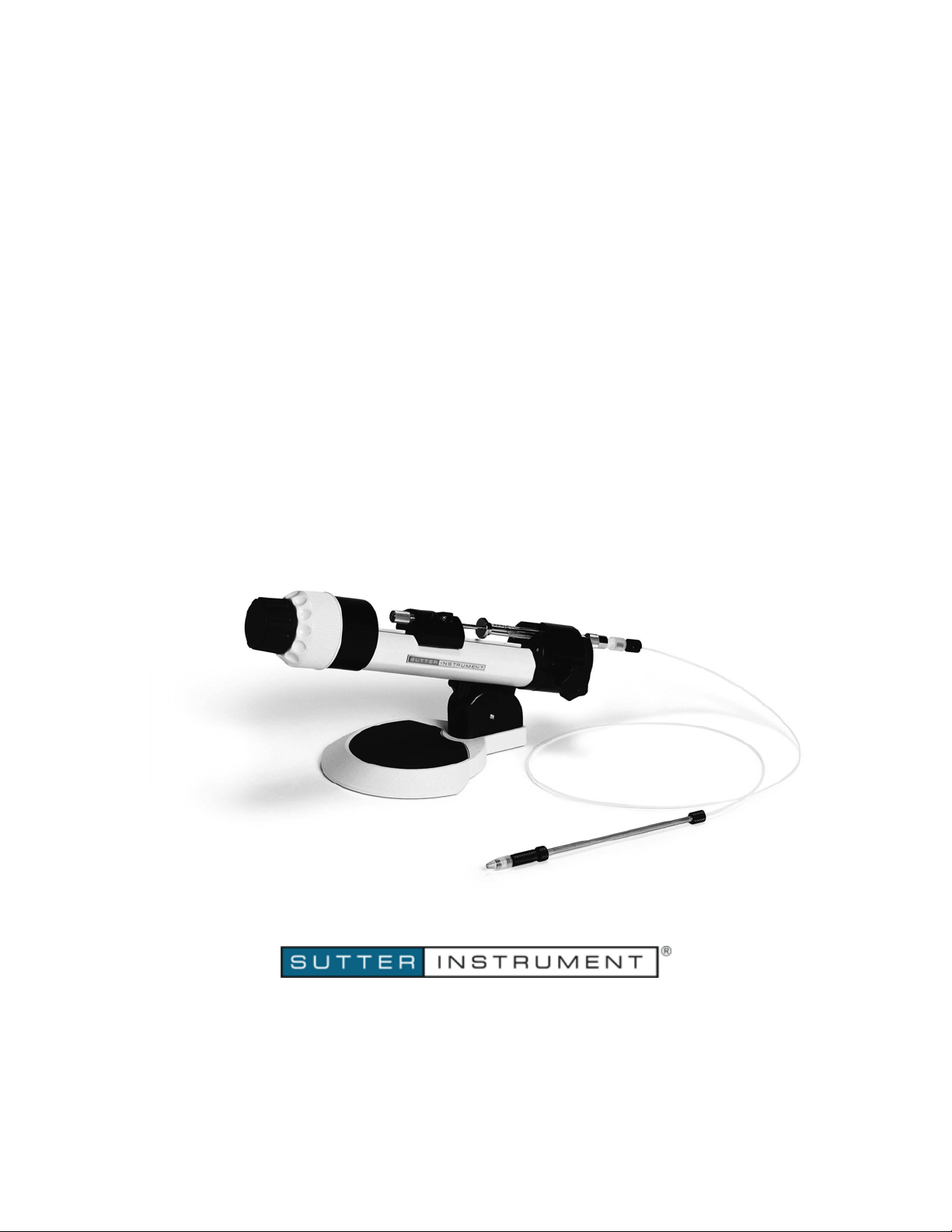
XenoWorks® BRI
Analog Microinjector
OPERATION MANUAL
Rev. 4.00 ( 20100521)
One Digital Drive
Novato, CA 94949
Voice: 415-883-0128 Web: www.sutter.com
Fax: 415-883-0572 Email: [email protected]
Page 2

ii
Q
Copyright © 2008-2010 Sutter Instrument Company. All Rights Reserved.
XenoWorks
®
is a registered trademark of Sutter Instrument Company.
XENOWORKS ANALOG MICROINJECTOR OPERATION MANUAL – REV.
4.00 (20100521)
Page 3
Page 4

Page 5

DISCLAIMER
The XenoWorks BRI Analog Microinjector should only be used in a laboratory
environment for use on animal tissues. It is not intended for use, nor should be used, in
human experimentation, or applied to humans in any way. This is not a medical device.
Do not open or attempt to repair the instrument without expressed and explicit
instructions from Sutter Instrument Company.
Do not allow unauthorized and or untrained operatives to use this device.
Any misuse will be the sole responsibility of the user/owner and Sutter Instruments
assumes no implied or inferred liability for direct or consequential damages from this
instrument if it is operated or used in any way other than for which it is designed.
PRECAUTIONS AND GENERAL SAFETY INFORMATION
Please read this manual carefully before operating the instrument.
Do not operate if there is any obvious damage to any part of the instrument.
As with all microinjection devices, sharp micropipettes can fly out of their holder
unexpectedly. Always take precautions to prevent this from happening. Never loosen the
micropipette holder chuck when the tubing is pressurized, and never point micropipettes
at yourself or others. Always wear safety glasses when using sharp glass micropipettes
with pressure microinjectors.
iii
Use this instrument only for microinjection purposes in conjunction with the procedures
and guidelines in this manual.
This instrument is designed for use with capillary glass micropipettes with an outer
diameter of 1mm. Adapters for other capillary diameters are available upon request.
Please retain the original packaging for future transport of the instrument.
Some applications, such as piezo-impact microinjection call for the use of mercury in the
micropipette tip. The use of any hazardous materials with any XenoWorks instrument is
not recommended and under taken at the users’ own risk.
This instrument has moving parts that may create pinch points. Take extra care not to
operate the instrument when there is a danger of crushing fingers or cables.
Always transport the instrument in its original foam packaging.
This instrument contains no user-serviceable components. This instrument should be
serviced and repaired only by Sutter Instrument or an authorized Sutter Instrument
servicing agent.
Operate this instrument only according to the instructions included in this manual.
This device is intended only for research purposes.
Sutter Instrument reserves the right to change specifications without prior notice.
For technical assistance, please contact your local Sutter Instrument dealer or (in the
U.S.) call 1-415-883-0128. You may also E-mail your queries to [email protected].
XENOWORKS ANALOG MICROINJECTOR OPERATION MANUAL – REV. 4 .00 20100521 ( )
.00 20100521 ( )
Page 6

i
v
(This page intentionally left blank.)
XENOWORKS ANALOG MICROINJECTOR OPERATION MANUAL – REV. 4
Page 7

v
TABLE OF CONTENTS
Disclaimer.................................................................................................................................................ii
Precautions and General Safety Information.......................................................................................iii
1. General Information............................................................................................................................1
1.1 Packing List.......................................................................................................................................1
1.2 Controls and Features...................................................................................................................... 2
1.2.1 Syringe Clamp ............................................................................................................................2
1.2.2 Plunger Clamp Screw ................................................................................................................ 2
1.2.3 Sliding Block ...............................................................................................................................2
1.2.4 Coarse and Fine Controls.......................................................................................................... 2
1.2.5 Angle Adjustment.......................................................................................................................3
1.3 Micropipette Holder.......................................................................................................................... 3
2. Assembly and Installation...................................................................................................................5
2.1 Installation and Assembly................................................................................................................5
3. Operating Instructions........................................................................................................................9
3.1 General...............................................................................................................................................9
3.2 Fitting a Micropipette.......................................................................................................................9
4. Maintenance.......................................................................................................................................11
4.1 Fitting New O-rings........................................................................................................................11
4.2 Troubleshooting ..............................................................................................................................11
Appendix A. Limited Warranty ............................................................................................................13
Appendix B. Accessories and Spare Parts............................................................................................15
Appendix C. Technical Specifications...................................................................................................17
Index .......................................................................................................................................................19
TABLE OF FIGURES
Figure 1-1. Components of the XenoWorks analog microinjector. ....................................................... 1
Figure 1-2. Analog microinjector controls and features. ........................................................................ 2
Figure 1-3. Micropipette holder components........................................................................................... 3
Figure 2-1. Attaching the tubing to the injector. ....................................................................................5
Figure 2-2. Connecting the tubing to the tip of the syringe................................................................... 6
Figure 2-3. Drawing hydraulic fluid into the syringe. ............................................................................ 7
Figure 2-4. Assembling the pipette holder............................................................................................... 8
XENOWORKS ANALOG MICROINJECTOR OPERATION MANUAL – REV. 4.00 20100521 ( )
Page 8

vi
(This page intentionally left blank.)
XENOWORKS ANALOG MICROINJECTOR OPERATION MANUAL – REV.
4.00 (20100521)
Page 9
1. GENERAL INFORMATION
1.1 Packing List
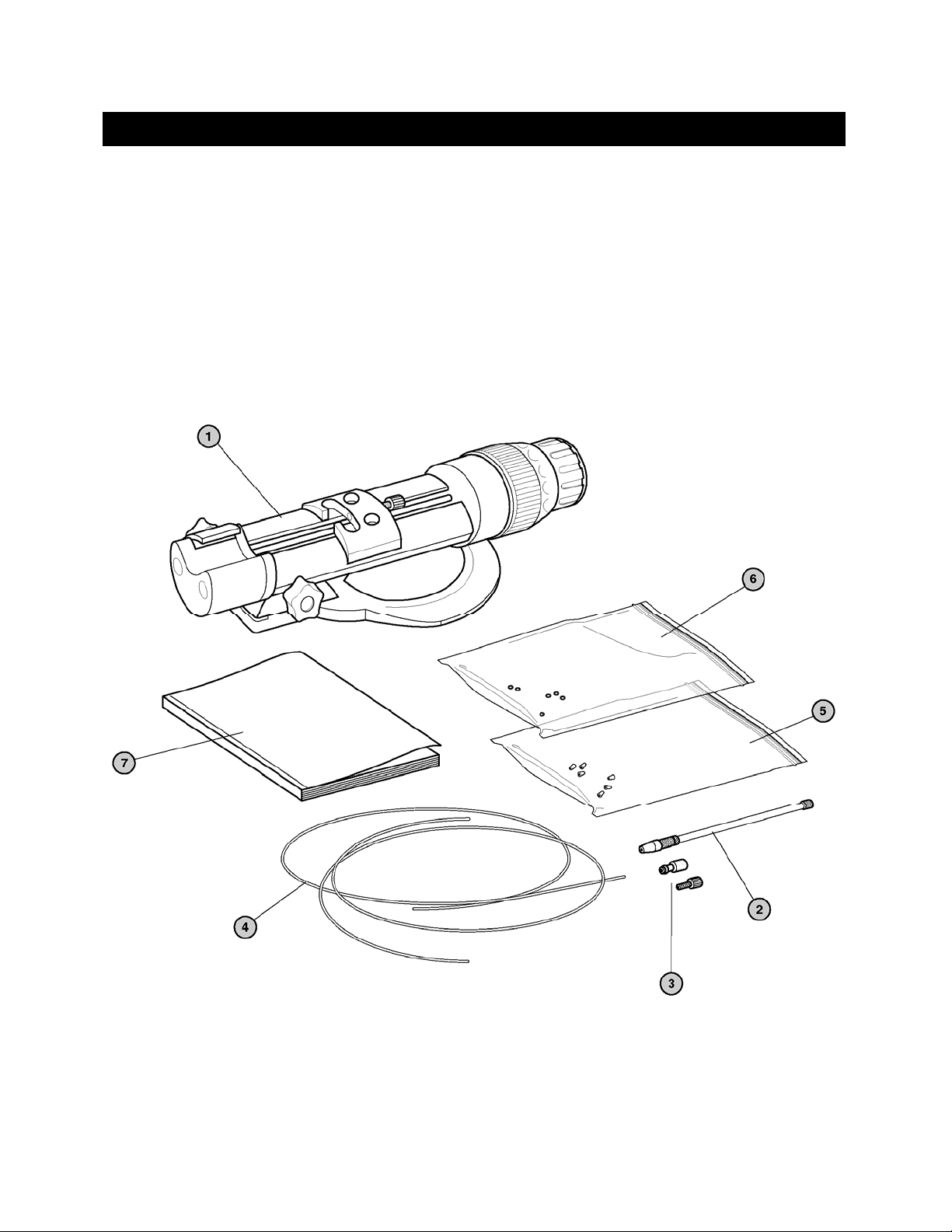
The XenoWorks™ analog microinjector is shipped with the following components.
1
1. Analog Microinjector Drive
2. Micropipette holder
3. Pressure fittings
5. Ferrules (6 pieces)
6. Spare O-rings (6 pieces)
7. Instruction manual
4. 1m tubing (2 pieces)
Use the Figure 1-1 to identify the parts listed. If any items are missing or damaged, contact
Sutter Instrument immediately.
Figure 1-1. Components of the XenoWorks analog microinjector.
NOTE: To operate the Analog Microinjector, an appropriate syringe is also required. A 500microliter syringe has been supplied and has been shipped along with the Analog
Microinjector. Please contact Sutter Instrument immediately if this item cannot be located.
XENOWORKS ANALOG MICROINJECTOR OPERATION MANUAL – REV. 4 .00 20100521 ( )
.00 20100521 ( )
Page 10
2
1.2 Controls and Features
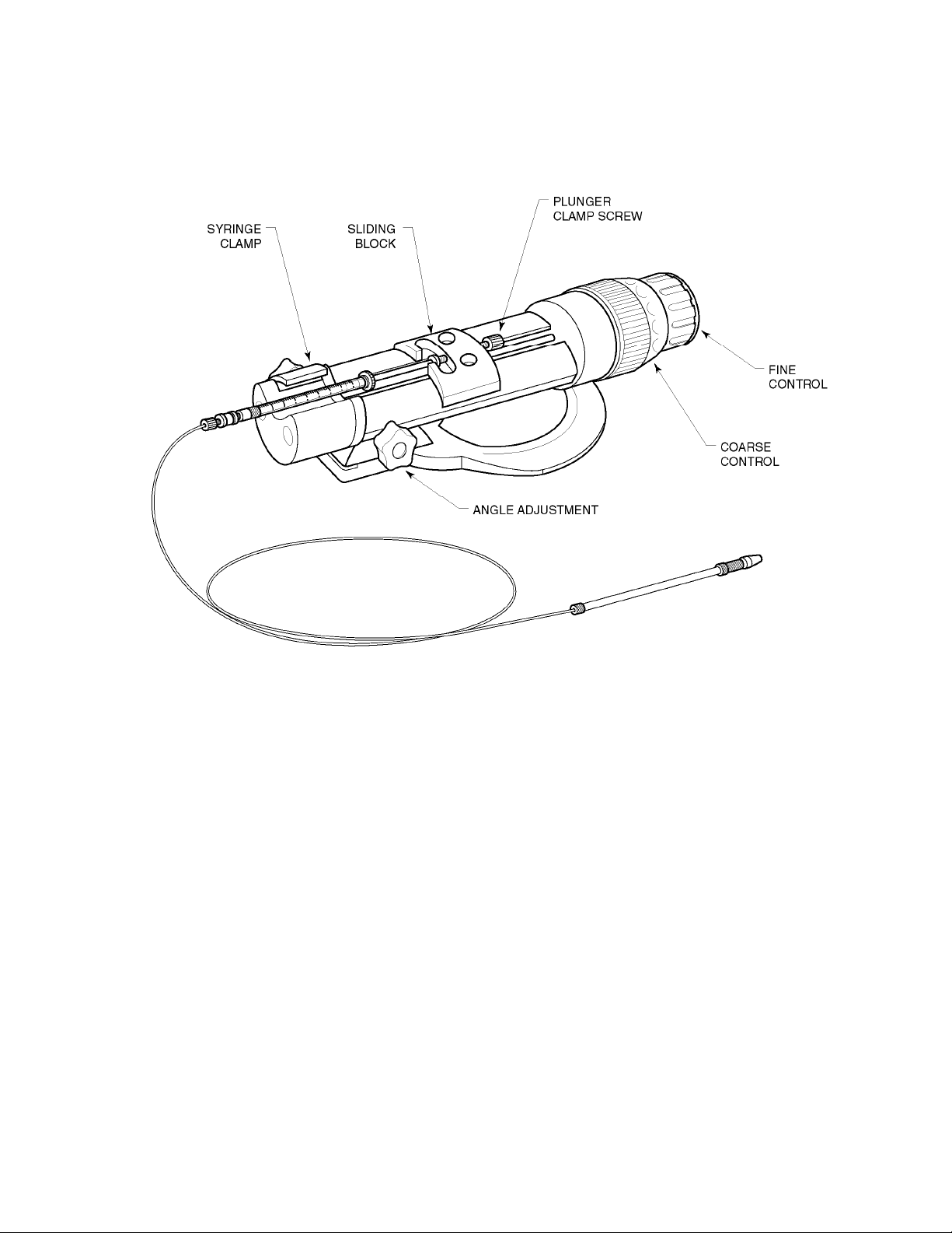
The figure below illustrates the XenoWorks Analog Microinjector fully assembled, complete
with syringe.
Figure 1-2. Analog microinjector controls and features.
1.2.1 Syringe Clamp
This holds the glass body of the syringe barrel gently and firmly in place. See below for notes
on syringe attachment.
1.2.2 Plunger Clamp Screw
This grips the end of the syringe plunger, allowing it to be pushed in and out of the syringe
barrel by the movement of the black sliding block.
1.2.3 Sliding Block
The sliding block is moved along the body of the analog microinjector, moving the syringe
plunger that it grips, in and out of the syringe barrel. The sliding block is moved by rotation
of the micrometer screw (which can be seen running the length of the inside body of the
microinjector). The micrometer screw is turned by rotation of the coarse and fine controls.
1.2.4 Coarse and Fine Controls
Turning the coarse and fine controls rotates the micrometer screw that moves the sliding
block up and down the body of the microinjector and in turn moves the syringe plunger.
Turning either control clockwise moves the syringe plunger into the syringe barrel, pushing
out the hydraulic fluid and injecting the contents of any attached micropipette. Conversely,
rotation of the controls counter-clockwise pulls the plunger out of the syringe barrel and
XENOWORKS ANALOG MICROINJECTOR OPERATION MANUAL – REV. 4 .00 20100521 ( )
Page 11
creates suction in the attached micropipette. One rotation of the coarse control is equivalent
to ten turns of the fine control.
CAUTION: THE CONTROLS SHOULD BE OPERATED INDEPENDENTLY;
OPERATING BOTH CONTROLS SIMULTANEOUSLY MAY DAMAGE THE UNIT.
1.2.5 Angle Adjustment
This knob is used to fix the microinjector at an angle appropriate for comfortable use.
1.3 Micropipette Holder
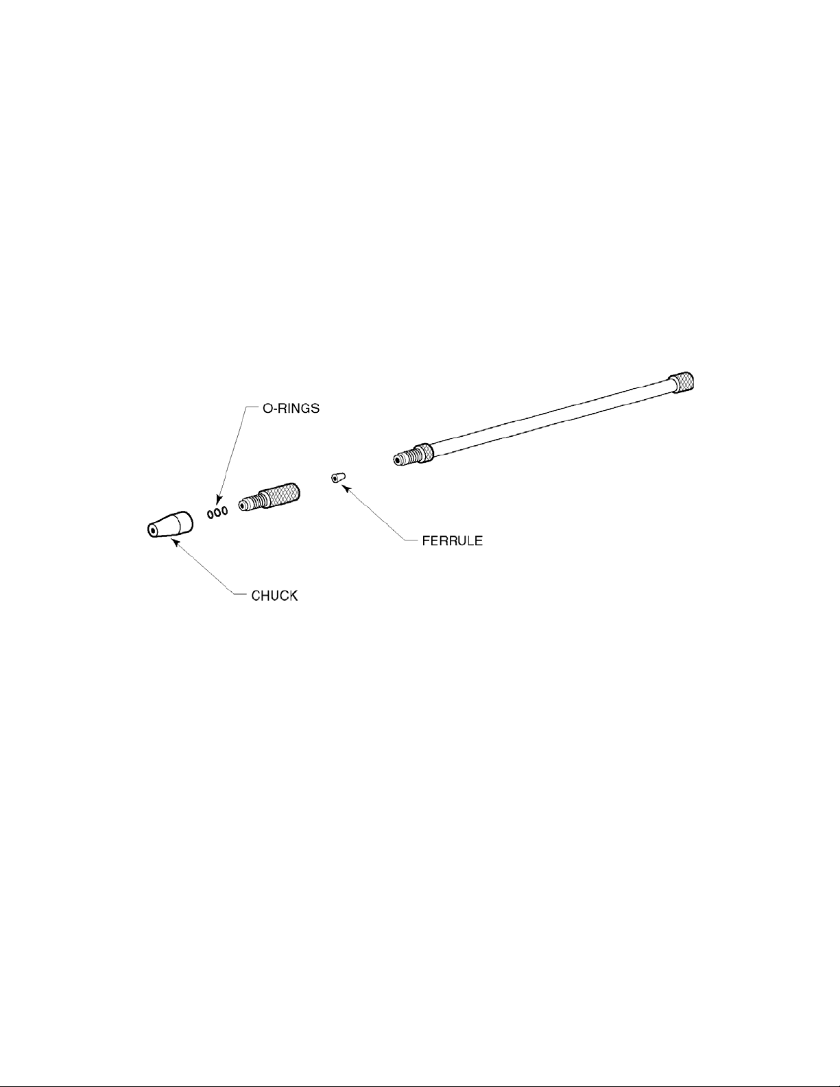
The micropipette holder is attached, via a length of tubing, to the tip of the syringe. The
default holder will grip a 1mm diameter capillary micropipette. The figure below shows the
micropipette holder disassembled.
3
Figure 1-3. Micropipette holder components.
XENOWORKS ANALOG MICROINJECTOR OPERATION MANUAL – REV. 4
Page 12

4
(This page intentionally left blank.)
XENOWORKS ANALOG MICROINJECTOR OPERATION MANUAL – REV. 4.00 (20100521)
Page 13
2. ASSEMBLY AND INSTALLATION
2.1 Installation and Assembly
The following steps describe the installation and assembly of the XenoWorks™ Analog
Microinjector.
NOTE: The XenoWorks™ Analog Microinjector is designed so that it can be assembled
without the need for tools. Do not use tools to tighten pressure fittings.
1. Unpack the XenoWorks Analog Microinjector drive and place it on a firm flat surface.
Ensure that the black sliding block is at approximately ¾ of its travel from the back of
the injector (the control end).
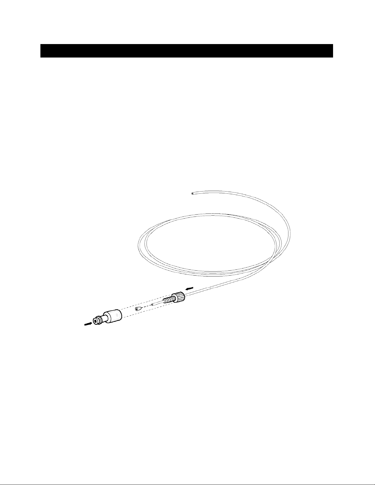
2. At one end of the tubing, attach the clear Luer connector and the black nut, capturing the
clear ferrule in between, as shown below. Take care to ensure that the angle of the ferrule
is pointing in the correct direction.
5
Figure 2-1. Attaching the tubing to the injector.
3. Unpack the syringe and ensure the plunger is pushed all the way in.
NOTE: If you have decided to use the system with air (instead of hydraulic fluid), skip to
Step 8.
4. Dip the tip of the syringe into a bottle or dish of the chosen hydraulic fluid, and gently
draw the plunger out so that the barrel fills completely with hydraulic fluid. Take care
not to draw the plunger up too fast since the fluid may cavitate and form air bubbles.
5. Turn the syringe upright, so that the tip is pointing upwards and allow any air bubbles to
float to the top. Gently tap the syringe to facilitate this.
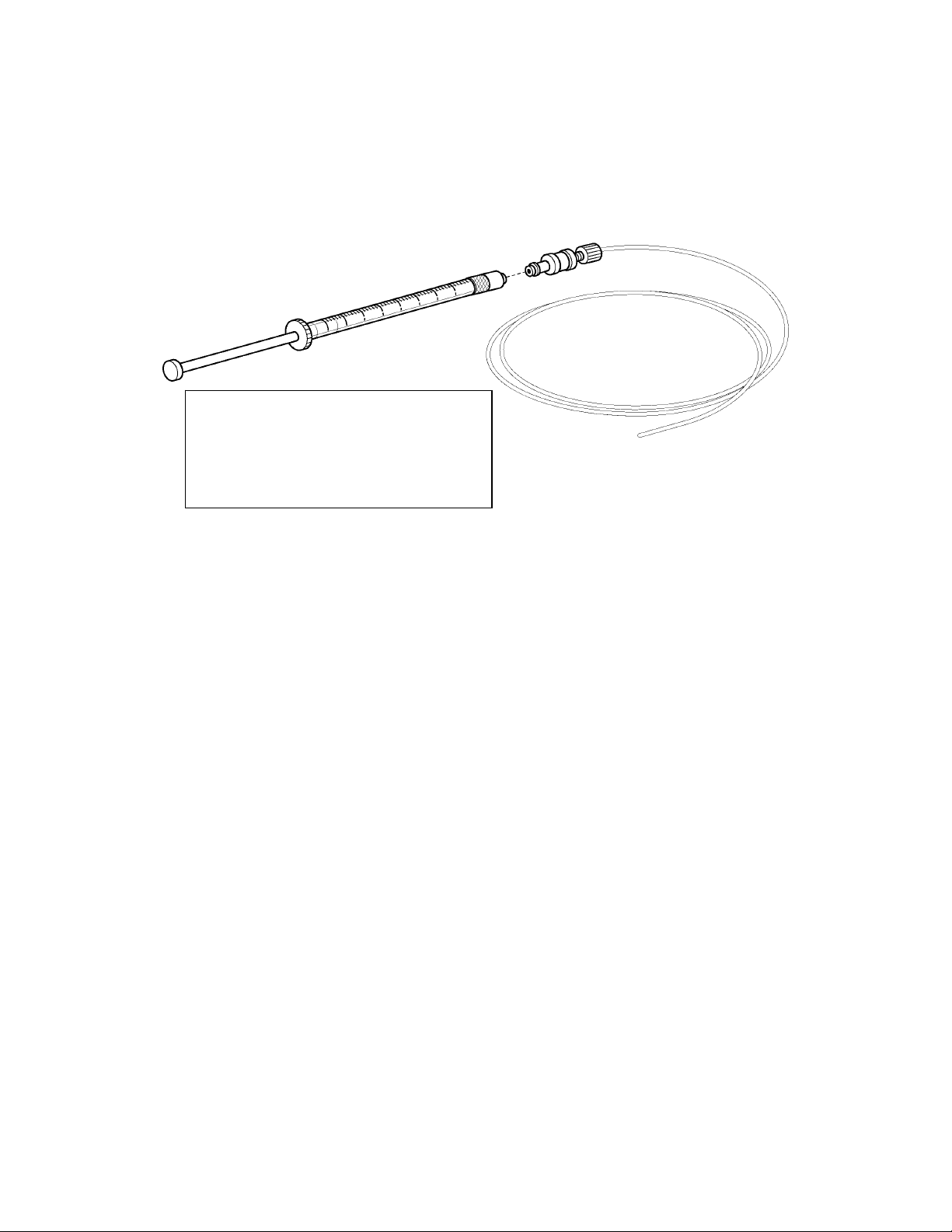
6. Connect the tubing to the tip of the syringe as shown Figure 2-2
and gently and slowly
push the plunger so that hydraulic fluid moves to the tip of the tubing.
XENOWORKS ANALOG MICROINJECTOR OPERATION MANUAL – REV. 4
.00 20100521 ( )
Page 14
6
NOTE: The tubing length supplied contains approximately 450 microliters of fluid. If a
syringe with less than 500 microliters volume is being used, a concomitantly shorter piece
of tubing must be attached, otherwise the fluid cannot be pushed to the tubing tip. A
guide to syringe volumes and appropriate tubing lengths is shown in the table in Figure
2-2, please refer to the Troubleshooting section for more information.
Syringe Volume Maximum Tubing
Length
1000 μl 1930 mm
500 μl 965 mm
100 μl 178 mm
Figure 2-2. Connecting the tubing to the tip of the syringe.
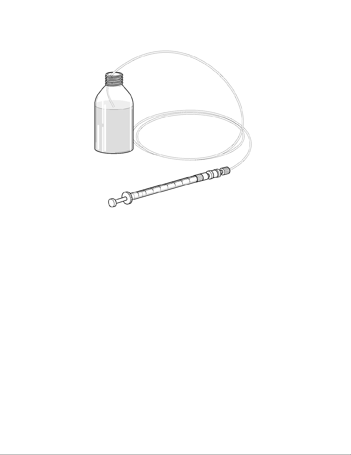
8. Once the hydraulic fluid has been pushed to the very tip of the tubing, dip the tip of the
tubing into the bottle or dish of hydraulic fluid and very slowly draw more hydraulic fluid
into the tubing until the syringe is approximately ¾ full. Again, take particular care not
to cavitate the hydraulic fluid or draw up any air bubbles. It may be necessary to repeat
Steps 3 - 7 until all bubbles are purged from the syringe and tubing.
XENOWORKS ANALOG MICROINJECTOR OPERATION MANUAL – REV. 4.00 20100521 ( )
Page 15
7
Figure 2-3. Drawing hydraulic fluid into the syringe.
9. Place the syringe into the Analog Microinjector drive, placing the end of the syringe
plunger in the sliding block. It may be necessary to use the microinjector’s coarse control
to reposition the moving block before the plunger will drop into place.
10. With one hand, hold the syringe clamp down on the syringe barrel and tighten the clamp
screw until the syringe barrel is held securely. Next, tighten the plunger clamp screw.
Take care to tighten the black syringe barrel clamp first before tightening the silver
plunger screw.
area, and do not over-tighten the clamp screws.
CAUTION: To avoid breaking the syringe, clamp only the smooth glass
11. Remove the free end of the tubing from the bottle or dish of hydraulic fluid (if used), wipe
it with a clean cloth and thread the tip of the tubing through the rear of the micropipette
holder and assemble the micropipette holder as shown below.
XENOWORKS ANALOG MICROINJECTOR OPERATION MANUAL – REV. 4
.00 20100521 ( )
Page 16
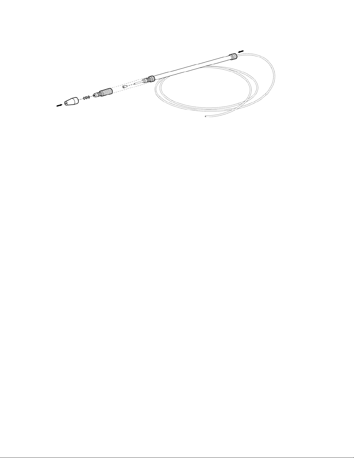
8
Figure 2-4. Assembling the pipette holder.
12. Adjust the tilt of the microinjector using the angle adjustment knob to achieve a
comfortable angle for working and place the unit on the bench top by the
micromanipulator.
Your XenoWorks Analog Microinjector is now set up and ready for use.
XENOWORKS ANALOG MICROINJECTOR OPERATION MANUAL – REV.
4.00 (20100521)
Page 17

3. OPERATING INSTRUCTIONS
3.1 General
Typically, the XenoWorks™ Analog Microinjector is used to vary slightly the pressure in the
tip of a glass micropipette, thus depositing or aspirating cells or cellular components. The
XenoWorks analog microinjector has been designed to work with a number of different
syringe volumes, with different tubing lengths and with different hydraulic fluids or simply
with air. In this way, the performance of the device can be precisely tuned to the application
for which it is used.
The microinjector can employ air, mineral oils or water as the hydraulic fluid, and syringe
volumes from 100 to 1000 microliters can be used. A 500 microliter syringe is supplied
standard with the device, but 100 and 1000 microliter models are available from Sutter
Instrument.
100 microliter – part number V001183
500 microliter – part number V001185
1000 microliter – part number V001186
The XenoWorks Analog Microinjector has two controls: coarse and fine. The coarse control
provides ten times the fluid displacement of the fine control. Turn the controls clockwise to
inject and counter-clockwise to aspirate.
9
3.2 Fitting a Micropipette
NOTE: If using air instead of a fluid in the microinjector, skip Step 1.
1. First, remove the clear chuck from the front of the micropipette, and turn the injector’s
coarse control clockwise to advance the hydraulic fluid to the end of the black aluminum
pressure fitting.
2. Replace the clear chuck, but do not tighten it yet.
3. Gently ease a micropipette whose maximum outer diameter does not exceed 1mm into the
chuck. The three black O-rings inside the chuck will create a little resistance, which can
be overcome by gently turning the micropipette holder body while simultaneously
pushing the micropipette in. Do not use excessive force. If the micropipette will not fit
snugly in the holder, the O-rings are either damaged or are obstructing the holder and
should be replaced.
4. The micropipette should be pushed into the chuck until the hard backstop is felt. At this
point, stop pushing and withdraw the micropipette 1 to 2 mm.
5. Gently tighten the chuck so that the O-rings are compressed, and form a seal around the
outer diameter of the micropipette.
may occur to the O-rings.
6. Turn the coarse control clockwise until the air-fluid meniscus is at the desired point in
the micropipette.
CAUTION: Do not over-tighten the chuck, or damage
7. The newly fitted micropipette and holder can now be attached to the micromanipulator in
readiness for microinjection.
XENOWORKS ANALOG MICROINJECTOR OPERATION MANUAL – REV. 4
.00 20100521 ( )
Page 18

10
(This page intentionally left blank.)
XENOWORKS ANALOG MICROINJECTOR OPERATION MANUAL – REV.
4.00 (20100521)
Page 19

11
4. MAINTENANCE
4.1 Fitting New O-rings
Routine use will create wear on the three black O-rings located in the tip of the micropipette
holder chuck. Occasionally, the O-rings will need to be replaced. To do this, gently remove
the old O-rings with an appropriate tool (a bent paper clip, for example). Discard the old Orings and insert three new ones, taking care to ensure that they are flat against the back of
the chuck. The new O-rings can be pushed down inside the chuck by gently screwing the
chuck onto the knurled black aluminum pressure fitting. Take care not to damage the chuck
during this procedure.
4.2 Troubleshooting
Problem Cause Solution
There is poor control by the
injector of the material in the
micropipette.
When drawing hydraulic fluid
into the syringe (without
tubing attached), air bubbles
are forming inside the syringe
plunger.
1. The black O-rings in the
chuck are damaged.
2. There is an air bubble in the
hydraulic fluid.
3. The syringe plunger clamp
or barrel clamp is not tight.
When filling the syringe for the
first time, a little air is trapped
inside the tip of the syringe,
which is drawn into the barrel
when the plunger is pulled
back.
Replace the O-rings.
Refill the system with
hydraulic fluid, taking care not
to introduce air bubbles.
Tighten the appropriate clamp
screws
Slowly draw hydraulic fluid
into the barrel, then
immediately and rapidly expel
it back into the container.
Repeat this until a full barrel
of hydraulic fluid can be drawn
without drawing air bubbles.
XENOWORKS ANALOG MICROINJECTOR OPERATION MANUAL – REV. 4
.00 20100521 ( )
Page 20

12
(This page intentionally left blank.)
XENOWORKS ANALOG MICROINJECTOR OPERATION MANUAL – REV.
4.00 (20100521)
Page 21

APPENDIX A. LIMITED WARRANTY
Sutter Instrument Company, a division of Sutter Instrument Corporation, limits the
warranty on this instrument to repair or replacement of defective components for one
year after the date of shipment, provided the instrument has been operated in accordance
with the instructions outlined in the instruction manual.
Abuse, misuse or unauthorized repairs will void this warranty.
Limited warranty work will be performed only at the factory, and the cost of shipment
both ways is to be borne by the user.
The limited warranty is as stated above and no implied or inferred liability for direct or
consequential damages is intended.
13
XENOWORKS ANALOG MICROINJECTOR OPERATION MANUAL – REV. 4
.00 20100521 ( )
Page 22

4
1
(This page intentionally left blank.)
XENOWORKS ANALOG MICROINJECTOR OPERATION MANUAL – REV.
4.00 (20100521)
Page 23

15
APPENDIX B. ACCESSORIES AND SPARE PARTS
The following spare parts are available for the XenoWorks Analog Microinjector from
Sutter Instrument Company.
V001180 10 μl Syringe
V001181 25 μl Syringe
V001182 50 μl Syringe
V001183 100 μl Syringe
V001184 250 μl Syringe
V001185 500 μl Syringe
V001186 1,000 μl Syringe
BR-MH Micropipette holder, includes micropipette holder body, 9 O-rings
BR-AT Analog tubing kit, includes 2 x 1 m ETFE tubing, Luer fitting, 6
ferrules
BR-OIL XenoWorks oil for injector
Adapters allowing the use of capillary glass micropipettes with outer diameter greater than
1mm are available upon request.
XENOWORKS ANALOG MICROINJECTOR OPERATION MANUAL – REV. 4
.00 20100521 ( )
Page 24

6
1
(This page intentionally left blank.)
XENOWORKS ANALOG MICROINJECTOR OPERATION MANUAL – REV.
4.00 (20100521)
Page 25

APPENDIX C. TECHNICAL SPECIFICATIONS
Coarse/Fine ratio 10:1
Displacement / turn*:
100-μl syringes: 1.04 μl coarse, 0.10 μl fine
500-μl syringes: 5.20 μl coarse, 0.52 μl fine
1,000-μl syringes: 10.40 μl coarse, 1.04 μl fine
Tubing: 1 m ETFE
Micropipette holder diameter: 4 mm
Micropipette compatibility: 1 mm capillary glass**
Piezo-impact drive compatibility: Prime Tech, Burleigh
17
Q
Storage Environment:
Temperature: 0 – 70°C
(32 - 158°F)
Humidity: 0 – 95% (non-condensing)
Operating Environment:
Temperature: 3.5 – 35°C
(38.3 - 95°F)
Humidity: 0 – 80% (non-condensing)
Size (without syringe): 250 mm x 127 mm x 96 mm
(9.84” x 5” x 3.79”)
Weight (without syringe): 1480 g
(3.26 lb (3 lb 4.21 oz))
* Displacements are given for Sutter Instrument-supplied syringes and are approximate.
Displacement will vary based on actual syringe used.
** Other micropipette glass diameters can be accommodated upon request.
XENOWORKS ANALOG MICROINJECTOR OPERATION MANUAL – REV. 4
.00 20100521 ( )
Page 26

18
(This page intentionally left blank.)
XENOWORKS ANALOG MICROINJECTOR OPERATION MANUAL – REV.
4.00 (20100521)
Page 27

INDEX
19
A
Assembly and Installation ......................................5
C
Controls and Features.............................................2
Angle adjustment.................................................3
Coarse control ......................................................3
Fine control ..........................................................3
Micropipette holder .............................................3
Plunger clamp screw ...........................................2
Sliding block.........................................................2
Syringe clamp.......................................................2
D
disclaimer ............................................................... iii
G
General Safety Information.................................. iii
I
Installation and assembly.......................................5
M
Maintenance.......................................................... 11
Fitting new O-rings.......................................... 11
N
notes
user..................................................................... 20
O
Operating Instructions............................................9
Fitting a micropipette .........................................9
P
Product Description ................................................1
S
Spare Parts............................................................ 15
Specifications ........................................................ 17
T
technical support ................................................... iii
Troubleshooting.................................................... 11
W
warranty................................................................ 13
XENOWORKS ANALOG MICROINJECTOR OPERATION MANUAL – REV. 4 .00 20100521 ( )
.00 20100521 ( )
Page 28

20
NOTES
XENOWORKS ANALOG MICROINJECTOR OPERATION MANUAL – REV. 4
 Loading...