

Page 1

UPS-1500-OL
with SX-1120 bundle
User
1500 VA Stand Alone Online Battery Backup
UPS-2000-OL
2000 VA Stand Alone Online Battery Backup
UPS-3000-OL
3000 VA Stand Alone Online Battery Backup
Manual
SX-BDL-1500
1500 VA Stand Alone Online Battery Backup
with SX-1115 bundle
SX-BDL-2000
2000 VA Stand Alone Online Battery Backup
© SurgeX | Technical Support: 80 0-645-9721 | surgex.com
Version 1.1
Page 2

On-Line UPS User Manual
Models: UPS -1500-OL, UPS-2000-OL, UPS-3000-OL
Table of Contents
1. EMC Statement s – FCC Part 15 3
2. Important Saf ety Instruc tions 4
3. Introduction 6
4. Product Des cription 6
Double Conversion On-Li ne T echnology 6
Diagnostic Tests 7
5. System Configuration 7
LED D esc riptions 9
LCD Descriptions 10
RS-232 Standard I nterface 10
SNMP Communications Option 11
Remote E m ergency Power O ff (REPO) Port 11
6. Determining t he P ower Requirements of Your Equi pm ent 11
7. Hardware Installation Guide 12
Installation 13
Standard Brac kets 13
19” Cabinet E ar Installation 13
Vertical I nstallation Steps 14
Wall-Mounted Installat i on Steps 14
19” Rack Mount using5 in 1 bracket 15
8. Rackmount Installation Steps 16
UPS Rai l Installation Instructions for 19” Cabinet 16
9. Initial C onnection and Startup 19
10. User’s Operat ions 22
Turning Of f the UPS when connected to an AC Source 22
Starti ng the UPS from a DC source (cold st art) 22
Turning of f the UPS when in DC Mode 22
Self Test Operation 23
Audible Al arm silence in DC Mode or Fault Mode 23
11. Batteries 23
Replaci ng the Battery 23
12. Troubleshooting 25
SX-BDL-1500, SX-BDL-2000
© SurgeX | Tec hnical Support: 800-645-9721 | surgex.com Page 1
Page 3

On-Line UPS User Manual
Models: UPS -1500-OL, UPS-2000-OL, UPS-3000-OL
13. LCD Fault Codes 26
14. Specifications 27
15. Appendix A : Extended Battery P ack User Guide 30
Esti m ated Run Time for U PS with Extended Bat tery Packs 30
LED D esc ription 32
Extended Battery Pack Operation 32
Extended Battery Pack Installat ion 34
Extended Battery Pack Q&A 35
16. Trademarks 36
SX-BDL-1500, SX-BDL-2000
© SurgeX | Tec hnical Support: 800-645-9721 | surgex.com Page 2
Page 4

On-Line UPS User Manual
Models: UPS -1500-OL, UPS-2000-OL, UPS-3000-OL
Thank you fo r selecting thi s uninterruptible pow er supply (UPS). It provides you with protection for connected equipment.
Please read this manual before installing the SurgeX SX-BDL-1500, SX-BDL-2000, UPS-1500-OL, UPS-2000-OL,
UPS-3000-OL as it provides important informat ion that should be fol lowed during inst allation and mai ntenance of the
UPS and batteri es, allowing y ou to correctl y set up your sy stem for the max imum safety and performanc e. Included is
information on cust omer sup port a nd serv ice, if it i s require d. If y ou experi ence a pr oblem with t he UPS , please ref er to
the Troubleshooting section in this manual to correct the problem. If the problem is not corrected, please collect
information so that the Technic al Support personnel can mo re effectivel y assist you.
SX-BDL-1500, SX-BDL-2000
1. EMC Statements – FCC Part 155
Notice: P ursuant to sect ion 15 of the FCC ru les, this product has been test ed and thereby c omplies to the
conditions of a Class B (SX-BDL-1500, UPS-1500-OL) and Class A (SX-BDL-2000, UPS-2000-OL, UPS3000-OL) digital device, which have been established for offering sufficient protection against dangerous
interferenc e for ins tallat ion i n a reside ntial area. Inst allation an d use of the e qui pment sho uld c omply w ith the
instructi ons provided in orde r to avoid such i nterference due to t he amount of radio fre quency energy that is
radiated and generated by the equipment. In spite of this, we cannot assure that a certain amount of
interferenc e may not occ ur in s ome ins tall ati ons . I f, by t urning o n a nd off , it c an be de duc ed t hat y our ra dio or
televisi on reception i s found to be i nfluence d by harmf ul interf erence from the equipm ent, it is recommend ed
to use one of the f ol lowing prevent i ve measure s.
• Place the recei ving antenna in a s eparate location or orientati on.
• Ensure a greater distance is achieved betw een the receiver and the equipment.
• Ensure that y our equipment is connected to an outlet on a separate circuit than the receiver.
• Contact a t echnician experienced with radio and TV or a dealer for further assi stance.
ICES-003
This Clas s B Interference Causing Eq uipment meets all requirements of the C anadian Interference Caus ing
Equipment R egulations I CES-003. Cet appareil num erique de la class e B respecte t outes les exigencies du
Reglement sur l e m ateriel brouilleur du Canada.
Declaration of Conformity R eq u est
Units label ed with a UL mark comply with the follow ing standards and directives:
• UL 1778
CAUTION: A shielded-type power cord is required in order to meet FCC emission limits and to prevent
interferenc e to t he nearby radi o or TV recept io n. I t is essent ial t hat only t he suppli ed power c ord be us ed. U se
only shielded c ables to connect I/O devices to this equipment.
Warning: Any changes or modif ic ati ons n ot ex press ly appr oved by th e ma nuf act ur er of t his dev ic e coul d voi d
the user’s authority to operat e the equipment .
© SurgeX | Tec hnical Support: 800-645-9721 | surgex.com Page 3
Page 5

On-Line UPS User Manual
Models: UPS -1500-OL, UPS-2000-OL, UPS-3000-OL
2. Important Safety Instructions (SAVE THESE INSTRUCTIONS)
CAUTION! (UPS hav ing Internal B atteries): R isk of elec trical shock – H azardous liv e parts i nside this uni t are
energized from the battery supply even when the input AC power is disconnected.
CAUTION! (No User serviceable Parts ): Risk of electrical shoc k, do not remove cover. No user servi ceable parts
inside. R efer servicing to qualified service personnel.
CAUTION! (Non-isolated Battery supply): Risk of electric shock, battery circuit is not is olated from AC input,
hazardous v ol tage may exist between battery terminals and ground. Test before touching.
WARNING! (Fuses): To reduce the risk of fire, replace onl y with the same type and size of fuse.
WARNING! Unit intended for installati on in a controlled environment.
CAUTION! Do not dispose of batteries in a fire, the battery may explode.
CAUTION! Do not open or mutilate the batt ery, released electrolyte is harmful to the skin and eyes.
CAUTION! A battery can present a ris k of el ectric shock and high s hort ci rcuit c urrent. The f ollowi ng precaut ion
should be observed when working on batteries:
• Remove wat ches, rings or other metal objects .
• Use tools wi th insulated handles .
To reduce the risk of electric shock, disconnect the UPS from the main supply before installing a computer
interface signal cable. Reconnect the power cord only after signaling interconnections have been made.
Servicing of batteries should be performed or supervised by personnel with knowledge of batteries and the
required precautions. K eep unauthorized personnel away f rom batteries.
These UPS uni ts are ex tremely heav y. Do not install t he UPS in a rac k or enclos ure by it s front tw o ears only .
Adjustable rac k rails are required for this t ype of installation.
The instruct ions contained within this s afety manual are deem ed important and should be clo sely follow ed at all
times during installation a nd follow-up maintenance of the UPS and batteries .
SX-BDL-1500, SX-BDL-2000
© SurgeX | Tec hnical Support: 800-645-9721 | surgex.com Page 4
Page 6
On-Line UPS User Manual
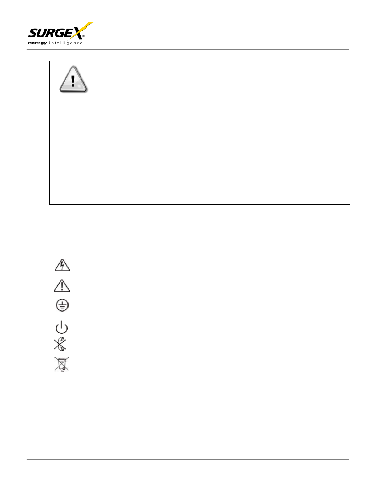
RISK OF ELECTRIC SHOCK – Please observe t he warning that a risk of electrical shock is present
CAUTION: REFER TO OPERATOR’S MANUAL – Refer to the operator’s manual for additional
information, such as important operating and maintenance i nstructions
SAFE GROUNDING TERMINAL – Indicates prim ary safe ground
LOAD ON/OFF – Pressing the button turns on/off the output receptac l es and the indicator light.
RJ45 RECEPTACLE – The receptacle provides network interface connections and telephone or
Please do not dis card of the UPS or the UPS batteries as the UPS may hav e valve-regulated l eadacid batteries. Please recycle batteries appropriately .
For additional safety instructions, please use the Safety Manual as a reference.
Special Symbols
The unit has a dangerous amount of voltage. If the UPS indic ator is on, the unit’s outlets may have a
dangerous amount of volt age even when not plugged into the wall outlet because the battery may continue
to supply pow er.
Care should be taken to undertake installati on indoors, free from electrically-conductive particles which are
under temperature and humidit y control, in order to reduce t he ri sk of electric shock.
It is best to disconnect the dev ice using the po wer supply cord. E nsure that the equi pm ent is placed in a
position near the outlet wher e easily accessible.
Except f or repl acing the batteries, all servicing on this equipment must be c arri ed out by qualified service
personnel.
Before conducting any maintenance, repair, or shipment, first ensure that everything i s turned off completely
and disconnected.
The following symbols us ed on the UPS warn y ou of precautions :
telecommunications equipm ent should not be plugged into it .
Models: UPS -1500-OL, UPS-2000-OL, UPS-3000-OL
SX-BDL-1500, SX-BDL-2000
CAUTION
© SurgeX | Tec hnical Support: 800-645-9721 | surgex.com Page 5
Page 7

On-Line UPS User Manual
3. Introduction
The informat i on provided in this manual covers single phase SX-BDL-1500, SX-BDL-2000, UPS-1500-OL, UPS2000-OL, UPS -3000-OL uninterruptible power sy stems, their bas i c functions, operating procedures, options
available and em ergency s ituations. It also includes inform ation on how to ship, store, handle, and install the
equipment. Onl y detailed req uirements of the UPS units are des cribed herein, and i nstallation must be carried
out in accordanc e with this manual. Electrical installation must also carefully follow local legislati on and
regulations. Only qualified personnel should conduct t hese installat i ons as failure to acknowledge electrical
hazards could prove to be fatal.
4. Product Description
Many different kinds of sens i tive electri cal equipment can be protected by an U ni nterruptibl e Power Supply
(UPS) incl uding computers, workstations, process control systems, telecommunic ations sys tems, sales
terminals, other critical i nstrumentation, etc. The purpose of the UPS i s to protect these systems from poor
quality uti l i ty power, com pl ete loss of power, or other associated problems.
Electric al interference exi sts in many forms, causing pro blems in AC pow er, from lightning, power company
accidents and radio transmis sion motors, ai r conditioners, and vending machines. Prot ection of sensitive
electrical equi pment is v i tal to protect against power outages, low or high volt age conditions , slow voltage
fluctuati ons, frequency variations, differential and common-mode noise, transients, etc.
To prevent pow er line problems from reaching critical systems causing damage to software, hardware, and
equipment malfunctions, the UPS maintains constant vol tage, isolati ng critical load output and cleaning the utility
AC power.
Models: UPS -1500-OL, UPS-2000-OL, UPS-3000-OL
SX-BDL-1500, SX-BDL-2000
Double Conversion On-Line Technology
A double conve rsion on-line tec hnology UPS provides complet ely isolated, clean, uninterrupted single-phase
power to your cri tical syst em s, while maintaining the batteries for their maximum potential. In the event t hat the
power failure lasts longer than the UPS bac kup time, the UPS w i ll shut down avoiding battery damage. When
the input AC voltage returns, the UPS wil l autom atically ret urn onl ine to recharge the batteries.
As shown i n fig. 1 block diagram:
• An input filter reduces transients on the inc oming utility .
• To maintain full battery char ge, the AC input power is rectified and regulated in the rectifier feeding
power to the batt ery converter and inverter.
• DC power is converted to AC i n the inverter, passing it on to the load.
• Power is mai ntained from the bat tery during a power failure.
• The converte r increases voltage appropri ately for the inv erter.
© SurgeX | Tec hnical Support: 800-645-9721 | surgex.com Page 6
Page 8

On-Line UPS User Manual
Diagnostic Tests
When the UPS is started, a diagnos tic test is automatically ex ecuted, check ing the electronic s and batteries,
reporting any problems on the LCD display. A diagnostic test can also be performed manually from the front
panel at any t ime.
Models: UPS -1500-OL, UPS-2000-OL, UPS-3000-OL
SX-BDL-1500, SX-BDL-2000
Figure 1 – Block Diagr am
5. System Configuration
The UPS devi ce and the internal batteries make up t he system. Dependi ng on the site and load requirements of
the install ation, certain additional options are available for the solution.
Planning a UPS system, the following should be taken into consi deration:
• The total dema nd of the protect ed system shall dictate the output power rating (V A ). Allow a margin for
future expansion or calculat i on inaccuraci es from measured power requirements.
• Backup tim e required will indi cate the battery size needed. I f the load is les s t han the UPS nominal
power rating, then actual back up time is longer.
• The following options are avail able:
o Extended Battery Packs
UPS-BPX-1500 for 1500
UPS-BPX-2000 for 2000/30 00
o Connectiv i ty Options –SNMP/WEB card
See the Specif ication section of this manual for additional model informat i on.
© SurgeX | Tec hnical Support: 800-645-9721 | surgex.com Page 7
Page 9
On-Line UPS User Manual
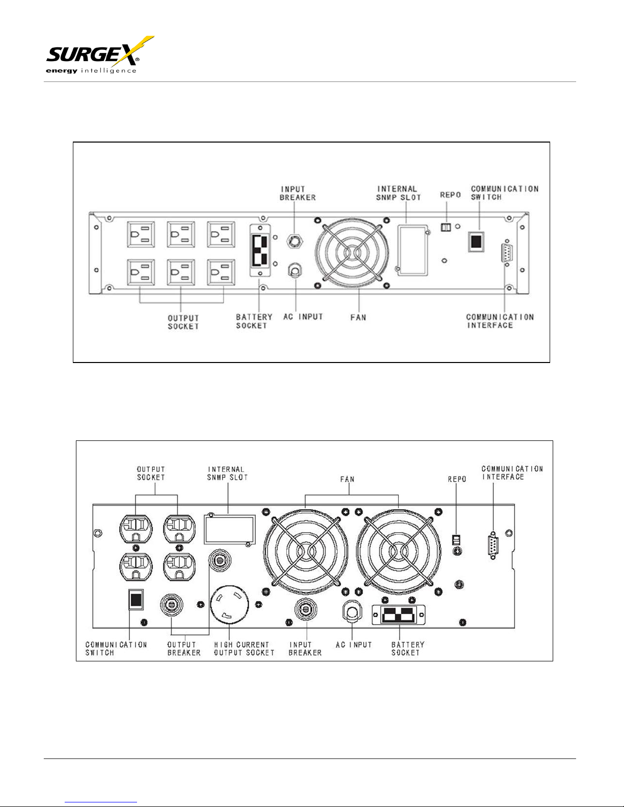
SX-BDL-1500/UPS-1500-OL REAR VIEW
SX-BDL-2000/UPS-2000-OL REAR VIEW
Models: UPS -1500-OL, UPS-2000-OL, UPS-3000-OL
SX-BDL-1500, SX-BDL-2000
© SurgeX | Tec hnical Support: 800-645-9721 | surgex.com Page 8
Page 10
On-Line UPS User Manual
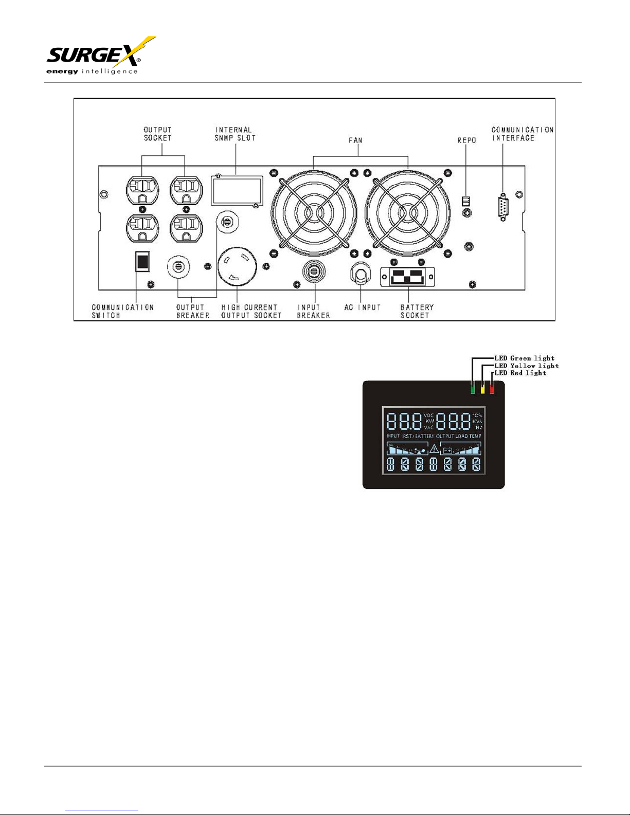
UPS-3000-OL REAR VIEW
FRONT PANEL
LED Description
The UPS has three LED’s on the f ront control panel.
These LED’s allow the user t o qui ckly understa nd if any
action is needed.
Yellow LED
Red LED
If this LED is i lluminated it indi cates a fault and
the UPS will have no output. Faults that would
indicate thi s alarm condition i nclude:
• Overload
• Inverter fault
• BUS fault
• Over temperat ure fault
If this LED is i lluminated it indi cates the user needs to take some action, and included:
• UPS in Bypas s Mode
• Batteries Overcharged
• Charger fault
• Fan fault
• Batteries di scharged to low voltage level
Green LED
If this LED is i lluminated it indi cates that ev erything is normal and the UPS is bei ng powered by
incoming AC utility or by the bat teries
Models: UPS -1500-OL, UPS-2000-OL, UPS-3000-OL
SX-BDL-1500, SX-BDL-2000
© SurgeX | Tec hnical Support: 800-645-9721 | surgex.com Page 9
Page 11

On-Line UPS User Manual
PIN #
FUNCTIONS
1,4,6,7,8
NOT USED
2
TRANSMIT
3
RECEIPT
5
GND
9
REMOTE WAKE UP
Models: UPS -1500-OL, UPS-2000-OL, UPS-3000-OL
LED Descriptions
There are four l i nes of information i n the LCD displ ay. Each line prov i des specif i c information relat ed to the unit
status and/ or operation. Lin e i nformation will be described from top to bottom with the top being li ne one.
Line One
Provides data i n to numeric s ections, wit h the data correspondi ng to the applicabl e category in l ine one
and two
Line Two
Allow s the user to identi fy which variabl e i nformation is bei ng displayed.
• Input
• Output
• Battery
• Load
• Temperature
This indicates t he status of the U PS.
RS-232 Standard Interface
The RS-232 interface uses a 9-pin f em ale D-sub connector. Inf orm ation provided inc ludes data about utility,
load and the UP S. The interface port pins and their functions are identified in the following table:
Line Three
This is a graphics secti on with load graphics on the left and battery graphics on t he ri ght. The fail ure
icon will appear in this section when a failure occurs.
Line Four
• ON LINE = utility mode
• ON BATT = batt ery mode
• ON BPS = bypass mode
• UPS OFF = standby m ode
SX-BDL-1500, SX-BDL-2000
CAUTION: MAX RATED VALUES 12VDC
© SurgeX | Tec hnical Support: 800-645-9721 | surgex.com Page 10
Page 12

On-Line UPS User Manual
SNMP Communications Option
The UPS provi des an intelligent slot for int ernal or external network card. This special int el ligent network card
can be compatibl e with popular software and h ardware found on t he web and in operati ng systems . It can
support oper ating system s such as HP Open View, IBM Netview , SUN Netmanager, et c. This enables the UPS
to provide instant UPS and power i nformation over the network. Please contact your reseller for additional
details.
N
OTES: The UPS can be monitored through the RS232 interf ace or the SNMP c ard, but only one way at a time.
The user can choose RS232 or SNM P communications through the c ommunications switch on the rear
panel of the UPS. RS232 is chos en if the switch is depressed to the R S232 position, and SNMP is
chosen if the switch is depressed to the SNMP position. When there are two or more monitored piec es
of equipment, the ground of each piece of equipment should be s hared. The SNMP card is configured
as DHCP by default IP setting.
Remote Emergency Power Off (REPO) Port
A customer supplied swit ch located remotely can be used to cl ose the REPO connection and allows the UPS
output receptacles to be switched off. S ince the REPO shut s down the equipment i m m ediately, orderly
shutdown procedures are not followed by any power management software. The UPS will have to be manually
restarted in o rder to regain power to the outlet s on the UPS.
Models: UPS -1500-OL, UPS-2000-OL, UPS-3000-OL
SX-BDL-1500, SX-BDL-2000
6. Determining the Power Requirements of your Equipment
A. Make sure the total Volt-Amp (VA) requi rements of your connected equipment does not exceed the
maximum VA rating for the UPS. The maximum VA rati ngs are shown in the Specificati ons section of this
document.
B. Ensure that the equipm ent plugged int o the battery-powered outlet s does not exceed t he UPS rated
capacity . If UPS rated capac i ties are exceeded, an overload c ondi tion may occur and cause the UPS to shut
down and trip the c i rcuit breaker.
C. If the power requirements of your equi pm ent are lis ted in values other t han Volt-Amps (VA), convert Watts
(W) or Amps (A) i nto VA by doing the calculations below. Note: T he equation below only calculates the
maximum amount of VA that the equi pm ent can use, not what is typi cally used by the equipment at any
given time. Users should expec t usage requirements to be appr oximately 60% of the value to es timate
power requirements:
Watts (W) x 1.43 = _____ VA or _____ Amps (A) x 120 = _____ VA
Add the totals for all of the equipm ent and multiply this total by 0.65 to calc ul ate actual power requirements.
N
OTE: Many factors can affect the amount of power that your c omputer system will require. The total load
that you wi l l be placing on the battery-powered outlets should not exceed 85% of the UPS capacity .
© SurgeX | Tec hnical Support: 800-645-9721 | surgex.com Page 11
Page 13

On-Line UPS User Manual
WARNING!
input voltage source. The UPS has its own internal energy source.
Ensure that all environmental concerns and requirements are m et according to specific ations
the unit may malfunction.
Models: UPS -1500-OL, UPS-2000-OL, UPS-3000-OL
7. Hardware Installation Guide
Inspect the UPS upon rec eipt. The packaging is rec yclable; keep i t for reuse or dispose of properly.
A. Safety Information
Information presented here is vital t o al l personnel. Please read all Safety information.
B. Storage and Transportation
Please handle the UPS and ass ociated equip m ent with extrem e caution since a hi gh amount of energy
is contained i n the batteries. A lways keep t he unit i n an upright position as marked on the packaging,
and never drop t he uni t.
Please adhere t o the following instructions i f the UPS is not i nstalled immedi ately:
• Store the equipment as is in its original packing and s hi pping carton.
• Do not store in tem peratures outsi de the range of -15° C to +25°C
• Ensure that the equipment is full y prot ected from w et or damp areas and from m oist air.
In order to maintain the batteries, the UPS should be recharged ev ery 6 months f or at least 8 hours.
If flammabl e substances such as gases or fumes are present, or i f the room is airti ght, a hazardous
situation may exist in whi ch no electrical equi pment should be operated.
The instruct ions in this manual explain how t o ins tall the UPS safely. Not acknow l edging such elec trical
hazards may be f atal – keep this manual for future r eference.
components have very high voltage and touching those components may be fatal.
Only a qualified technician or authorized agent m ay service the unit.
The UPS unit’s output receptacl es carr y l ive voltage even when not connected to an
C. Environment
listed in t hi s document, otherwise the safety of installation personnel can not be guarantee d, and
Ensure that y ou rem ember the fol l owing when loc ating the UPS sy stem and battery options:
• Avoid extrem es of temperatur e and humidity. M aximum battery life can be attained with a
recommende d temperature range of +15°C to +25°C.
• Provide prot ection for the equipment from moi sture.
• Space and ventil ation requirements must be m et. Ensure there is 100mm behind and 50mm on the
sides of the UPS for proper vent i lation.
• Ensure that the front of the UP S remains clear for us er operation.
© SurgeX | Tec hnical Support: 800-645-9721 | surgex.com Page 12
It is strongly recommended that the UPS cabinet not be opened as
SX-BDL-1500, SX-BDL-2000
Page 14

On-Line UPS User Manual
SX-BDL-1500 / UPS-1500-OL
Use M4 x 6 screws on p laces marked with a letter A
SX-BDL-2000 / UPS-2000-OL / UPS-3000-OL
Use M4 x 6 screws on p laces marked with letter A
19” Cabinet Ear Installation
2U 5 IN 1 BRACKET FOR
3U 5 IN 1 BRACKET FO R
D. Rack-Mount Accessories
SX-BDL-1500 / UPS-1500-OL
Models: UPS -1500-OL, UPS-2000-OL, UPS-3000-OL
SX-BDL-1500, SX-BDL-2000
SX-BDL-2000/UPS-2000-OL, UPS-3000-OL
© SurgeX | Tec hnical Support: 800-645-9721 | surgex.com Page 13
Page 15

On-Line UPS User Manual
SX-BDL-2000 / UPS-2000-OL / UPS-3000-OL: Use M5 x 12 screws on places marked wi th letter B
SX-BDL-1500 / UPS-1500-OL
Use M5 x 12 screws on p laces marked with letter B
Wall-Mounted Installation Steps
SX-BDL-2000 / UPS-2000-OL / UPS-3000-OL
SX-BDL-1500 / UPS-1500-OL
Vertical Installation Steps
Models: UPS -1500-OL, UPS-2000-OL, UPS-3000-OL
SX-BDL-1500, SX-BDL-2000
© SurgeX | Tec hnical Support: 800-645-9721 | surgex.com Page 14
Page 16

On-Line UPS User Manual
SX-BDL-1500 / UPS-1500-OL
SX-BDL-2000 / UPS-2000-OL / UPS-3000-OL
19” Rack Mount Using 5 in 1 Bracket
Use M5 x 12 screws on p laces marked with letter B
Use M5 x 12 screws on p laces marked with letter B
Models: UPS -1500-OL, UPS-2000-OL, UPS-3000-OL
SX-BDL-1500, SX-BDL-2000
© SurgeX | Tec hnical Support: 800-645-9721 | surgex.com Page 15
Page 17

On-Line UPS User Manual
A.
B.
C.
2U EAR FOR UPS OR BPX
MOUNTING IN C ABI NE T
EXPANDABL E RAIL FOR UPS OR BPX MOUNTING IN CABINET
MOVEABLE NUT FOR
8. Installation of Rack Mount and Accessories
Models: UPS -1500-OL, UPS-2000-OL, UPS-3000-OL
SX-BDL-1500, SX-BDL-2000
MOUNTING RA IL KI T
IN CABINET
© SurgeX | Tec hnical Support: 800-645-9721 | surgex.com Page 16
Page 18

On-Line UPS User Manual
D.
E.
UPS FRONT VIEW AFTER INST ALLING 2U EARS
ASSEMBLE THE RAIL ONTO THE CABINET U-BAR WITH
SCREWS AT FRONT & BACK USING MOVABLE NUTS
Models: UPS -1500-OL, UPS-2000-OL, UPS-3000-OL
SX-BDL-1500, SX-BDL-2000
© SurgeX | Tec hnical Support: 800-645-9721 | surgex.com Page 17
Page 19

On-Line UPS User Manual
F.
G.
PUSH THE UPS OR BPX INTO THE CABINET VIA THE RAIL
FROM THE FRONT
ATTACHE UPS OR BPX EAR ONTO CA BINET U-BAR WITH
SCREWS ON BOT H LEF T & RIG HT S IDES
N
OTE: Any external Bat tery Packs must be installed next t o or under the UPS. P lease refer to
Appendix A: Battery Pack User Guide for more i nformation when installing these.
Models: UPS -1500-OL, UPS-2000-OL, UPS-3000-OL
SX-BDL-1500, SX-BDL-2000
© SurgeX | Tec hnical Support: 800-645-9721 | surgex.com Page 18
Page 20

On-Line UPS User Manual
Models: UPS -1500-OL, UPS-2000-OL, UPS-3000-OL
SX-BDL-1500, SX-BDL-2000
9. Initial Connection and Startup
Ensure that the UPS and optional battery pack s are mounted correc tly, and the U P S is disconnected from i nput
power before p roceeding.
A.
Connections Installation
1. Connect external battery packs (option)
CAUTION: CONNECT ONLY BATTERY PACKS PROVIDING THE SAME DC VOLTAGE AS THE UPS –
PLEASE DOUBLE CHECK LABELING ON THE UPS AND BATTERY PACKS TO ASSURE PROPER
VOLTAGES ARE CONNECTED. CONNECTING THE INCORECT BATTERY PACK TO THE UPS MAY
RESULT IN DAMAG E TO THE UPS AND/OR BATTERY PAC K THAT WILL VOI D THE WARRANTY .
• Ensure that the U PS is disconnected from AC input and is off while connecting the External
Battery Packs. Ensure all battery breakers are in the “OFF” position.
• Remove the EB P covers on t he UPS and EB P. C onnect the batt ery cable th at comes w ith the
External Bat tery Pack bet ween the External Battery Pack t o the UPS.
• Secure the DC battery cable to the rear of the UPS, and the rear of t he EBP by using M3 x 8
screws provided (2 each per connector end).
• Connect the 5-15P from the EBP to an i nput AC uti l ity source per spec i fications.
• Connect a sec ond battery pack to the firs t EBP i n the same fashi on if more th an one is t o be
installed.
• Refer to Appendix A: Battery Pack User Manual for more details
2. Connect SNMP card (option)
• Remove the two screws securing the SNMP cover plate on the rear of the UPS, and sl ide the
SNMP NetA gentII card into t he slot. Secure the card into the slot with the two screws
previously rem oved.
3. Close the batt ery b r eakers on the Optional battery p acks if installed .
4. Connect Devi ces to UPS
A. Plug the equi pment/dev ices that require bat tery bac k-up into the back of the UPS. Avoid us ing
an extension c ord.
• Be sure to plug your core equipment (e.g. computer, monitor, critical data storage
device, etc.) into the Battery Power supplied outlets.
• Plug your peripher al equi pment (e.g. printer, sc anner, fax , audi o dev ice) t o the B ypass
outlet(s).
• Do not plug a laser printer i nto the UPS output outlet s, as its power demand is much
higher than ty pic al p erip heral s and m ay c ause the c irc uit breake r t o trip. It is sugges t ed
that laser printers and other heavy loads be connected to the Bypass outlets.
© SurgeX | Tec hnical Support: 800-645-9721 | surgex.com Page 19
Page 21

On-Line UPS User Manual
5. Connect to Utility Power
For UPS-1500-OL, UPS-2000-OL, UPS-3000-OL Models only:
(For SX-BDL-1500 and SX-BDL-2000 connection installation, skip to instructions below)
A. Plug the UPS into a 3 -wire grounded rec eptacle of p roper size per UPS specifi cations. Make
sure the r ecept acl e is p rot ect ed by t he pr ope r si ze f use or c irc uit bre ak er, a nd is not l ocat ed on
the same circuit with equipment requiring higher amounts of power (e.g. refrigerator, air
conditioner, copier). Avoid using an extension cord to connect the UPS to the input power
receptacle.
• NOTE: Size of Branch Circuit Over-current Protection – CAUTION – to reduce the risk of
For SX-BDL-1500 and SX-BDL-2000 Models only:
(For UPS-1500-OL, UPS-2000-OL, and UPS-3000 connection installation instructions , refer to
instructions above)
A. Connect UPS to SX -1115: Plug the UP S power c ord into the SX-1115 (into th e receptacle on
the back of t he SX-1115). Avoid using an extensi on cord.
B. Then plug the SX-1115 into a 3-wire grounded rec eptacle of proper siz e. Make sure the
receptacle is protected by the proper size fuse or circuit breaker, and is not located on the sa m e
circuit with equipment requiring higher amounts of power (e.g. refrigerator, air conditioner,
copier). Avoi d using an extension cord to conn ect the SX-1115 to the input power receptacle.
C. NOTE: Size of Branch Circ uit Over-current Protection – CAUTION – to reduce the risk of fire,
connect only to a circuit provided with 30 ampe res maximum branch circuit over-current
protection in accordance wi th National Electric Code, ANSI/NFPA 70.
6. Connect Telephone or Data Device
A. If you wish to protect a fax, modem or other telephone or data networking devic e, plug the cable
from the w all into the “IN” jack . Connect the cable provi ded with the UPS from t he “OUT” jac k to
the fax, modem , or other networking dev ice. To protect a 10B ase-T (UTP) network i nterface,
obtain and use a UTP cable to connect the “OUT” jack to your computer.
7. Charge Batteri es: Once the U PS has been c onnected t o an AC power sourc e the inte rnal charger
will start charging the UPS batteries, at this point the yellow LED is illuminated, and the LCD
displays “UPS OFF”. In this state the output voltage is zero, which means UPS has no output.
Please reali ze th at alth ough y ou may sta rt usi ng th e UPS i mmediat ely, maximum b ack -up time will
still not be available, so it i s recomm ended to c harge the bat teri es for a mi nimum of 6 h ours bef ore
use.
Models: UPS -1500-OL, UPS-2000-OL, UPS-3000-OL
SX-BDL-1500, SX-BDL-2000
fire, connect only to a circuit provided wi th 30 amperes maximum branch circui t overcurrent protection in accordance with N ational Electric Code, ANSI/NFPA 70.
© SurgeX | Tec hnical Support: 800-645-9721 | surgex.com Page 20
Page 22

On-Line UPS User Manual
B. Startup Installation
1. Start and configure the UPS
On/Off Button Function Button Inquiry Button
• Press and hold the ON/OFF button f or more than 3 seconds to turn on the U PS. The UPS
should now st art its inspection of the internal functions, main synchronization, and inverter
startup. Then power should st art to be supplied via the outlets. Once turned on, the UPS will
perform a self-test function, when the yellow LED turns t o green, LCD displays “on line”, and
means UPS i s working in utili ty mode.
2. Configure the local monitoring software if desired.
• Insert the U PSilon 2000 CD (i ncluded with UPS packaging) into the CD ROM of the l ocal
computer.
• Select “Inst al l program” from the Autorun men u and choose for the correct operati ng system .
• Follow the s etup instructi ons. Enter the product key when prompt ed. The software key is found
on the CD cover. Click fini sh when prompted.
• The UPSILON icon will appear in the system tray of the desktop near the syst em clock. Double
click this icon to enlarge the program window .
• Connect the RS232 cable (included in the UPS packaging) to the C om puter and UP S .
Communicat i on should start momentarily. If it does not, cli ck on Settings up on t he UPSilon
toolbar, the n select a diff erent Comport until communication i s established.
• Click on “Manual” in the UPSILON toolbar for further software configuration.
NOTE: PLEASE VERIFY AUTOMATIC SHUTDOWN TIME PARAMETERS IN THE SETTINGS
SECTION FOR YOUR SPECIFIC INSTALLATION.
3. Configure the o p tional NetAgen tII SNMP card if installed.
• Insert the N etAgent Util it y CD (included with SNMP packagi ng) i nto a PC and downloa d the
user manual
• Install Netility from the A utoRun menu
• Connect a network cable from t he PC to the SNMP card.
• Run Netili ty program and it wi l l auto-search and l i st available N etAgents (SNMP card)
• Highlight and c lick “Configu re” to change the n etwork sett ings on the NetAgent discovered.
• Disconnec t the cable to the PC and connect the SNMP card to your netw ork.
• Access the SNMP card via the network and make c onfiguration changes using the manual
downloaded previously.
NOTE: PLEASE VERIFY AUTOMATIC SHUTDOWN TIME PARAMETERS IN THE SETTINGS
SECTION FOR YOUR SPECIFIC INSTALLATION.
Models: UPS -1500-OL, UPS-2000-OL, UPS-3000-OL
SX-BDL-1500, SX-BDL-2000
© SurgeX | Tec hnical Support: 800-645-9721 | surgex.com Page 21
Page 23

On-Line UPS User Manual
Models: UPS -1500-OL, UPS-2000-OL, UPS-3000-OL
4. After chargi n g is complete, co n nect the l o ads to the UPS while monitoring the l o ad levels via
the UPS LCD o r via the software.
• Do not connect any devices that have the possibi l ity of overloadi ng the UPS.
Refer to the Troubleshooting section and/or Technical Support with any problems during setup.
10. User’s Operations
The only operations that users are permitted to do are:
• Turning the UPS unit ON or OFF
• Operating the us er interfaces
• Connecting dat a i nterface cabl es
• Changing the bat teries
All such operat ions are to be performed exact l y as instruc ted in this manual. The greatest care pos sible must be
taken for any of these operations , and any change thereof may prove v ery hazardous to the operator.
On/Off Button Function Button Inquiry Button
Turning Off the UPS when connected to an AC source
• Press and hold the ON/OFF button f or more than 3 seconds to turn off the UPS. This m eans the internal
inverter has been deactiv ated.
• The unit will run a self test pri or to the deactivation of the invert er.
• The green LED w i ll be off and the yel l ow LED will be on. T he LCD display wi l l indicate “On BP S ”, which
means the UPS in providing no out put.
Starting the UPS from a DC source (cold start)
• Assure that the UPS has fully charged batterie s and the internal battery pack is connected.
• Assure that there is no AC input power source and/or the unit is not pl ugged into an outlet.
• Press and hold the ON/OFF button f or three sec onds.
• Once turned on, the UPS wil l perform a self-test function, when the yellow LE D turns to green, LC D
displays “On Bat t” – the UPS is now functioning in D C mode.
Turning Off the UPS when in DC Mode
• Press and hold the ON/OFF button f or more than 3 seconds to turn off the UPS. This m eans the internal
inverter has been deactiv ated.
• During the shut down period, the UPS will run a s elf test. Once t he self-test has been completed,
assuming there i s still no AC i nput, the LCD will no l onger display information. Thi s indicates the UPS
has no output.
SX-BDL-1500, SX-BDL-2000
© SurgeX | Tec hnical Support: 800-645-9721 | surgex.com Page 22
Page 24

On-Line UPS User Manual
Models: UPS -1500-OL, UPS-2000-OL, UPS-3000-OL
Self Test Operation
Please refer to the three operating but tons on the front panel of the U P S.
• Confirm the UPS is in “Utility Mode”.
• Press and hold the “Function ” button for a mini m um of two seconds.
The self-test will last for 10 s econds, during t his time the LED’s will be lit in a sequential, repe ating fashion
Audible Alarm silence in DC Mode or Fault Mode
• When the UPS is in DC Mode, the audible alarm wil l sound every four (4) s econds. Press and hold the
“Function” But ton for a minimum of two (2) seconds to disable the audible alarm.
• When the UPS is in Fault Mode, the audi ble alarm wi ll continuously sound. Press and hold the
“Function” But ton for a minimum of two (2) seconds to disable the audible alarm.
11. Batteries
REPLACING THE BATTERY (Qualified Service Personnel Only)
CAUTION! Read and follow the IMPORTAN T SAF ETY INSTRUC TIONS before servi cing the battery. Service
the battery under the superv i sion of Qualified Service Personnel knowled geable of batteries and their
precautions.
CAUTION! Use only the specified ty pe of battery. See your deal er for replacem ent batteries.
CAUTION! The battery may present risk of electrical shock. Do not di spose of batteries in a fire as it may
explode. Follow all local ordinances rega rdi ng proper disp osal of batteries.
CAUTION! Do not open or muti l ate the batteri es. Released electrolyte is harm ful to skin and eyes and may be
toxic.
CAUTION! Although the battery system volt age i s only 12VDC and 24VDC, the battery can present a high risk
of short circuit current and electrical shock. The short circuit current capability of the battery is sufficient to burn
wire or tools very rapidly, producing molten metal. Observ e these precautio ns when replaci ng the battery:
A. Remove all watches , rings or other metal objects.
B. Only use tools wit h insulated handles.
C. Do not lay tools or metal parts on top of battery or any termi nals.
D. Wear protective ey e wear (goggles), rubber gloves, and boots.
E. Disconnect the c hargi ng source before connecting or di sconnecting t he battery terminals.
F. Determine if the battery is inadvertently grounded. If inadvertently grounded, remove the sourc e of the
ground. Contact with a ground ed battery can result in elect ri cal shock! The li kelihood of such shock will
be reduced if such grounds are rem oved durin g installation and m aintenance (applicable to a UPS and
a remote batt ery supply not having a grounded circuit).
SX-BDL-1500, SX-BDL-2000
© SurgeX | Tec hnical Support: 800-645-9721 | surgex.com Page 23
Page 25

On-Line UPS User Manual
Models: UPS -1500-OL, UPS-2000-OL, UPS-3000-OL
SX-BDL-1500, SX-BDL-2000
Slide the plastic cover to the right
Remove the M5 x 10 screws on the right side
Remove plastic front cover
Locate the battery tray on the right front side of the UPS
Remove (4) M4x6 screws marked with letter A.
Remove the battery tray from the UPS.
© SurgeX | Tec hnical Support: 800-645-9721 | surgex.com Page 24
Page 26

On-Line UPS User Manual
Audible
Alarm
The “Input”
flashing
Two Beeps
seconds
Verify that utility vol tage and frequency i s
The “Input”
flashing
Check UPS batteries. If necessary
Utility Normal-
AC input
1. If batteri es are undercharged let UPS
1. Depress the “On/Off” button for at least
Review abnormal process i nformation
12. Troubleshooting
© SurgeX | Tec hnical Support: 800-645-9721 | surgex.com Page 25
Issue
letters in t he
second row of
the LCD are
letters in t he
second row of
the LCD are
Battery
Indicator
Flashing
UPS has no
Insufficient
battery runtime
UPS will not
start aft er
pressing the
“On/Off”
button
Major fault
detection by
the UPS
per second
at startup f or
8 total
One beep
per 2
minutes
One beep
per second
N/A
Once every
4 seconds
in DC mode
N/A
Constant
beep
Models: UPS -1500-OL, UPS-2000-OL, UPS-3000-OL
SX-BDL-1500, SX-BDL-2000
Alarm Descr iption What You Should Do
The Input Voltage or frequency
may be beyond th e normal
acceptable range.
Possible mis-wiring AC line and
neutral line
Batteries are undercharged,
disconnect ed or need to be
replaced.
Possibil i ty that circui t break er on
UPS has t ri pped
“On batt” displayed on LCD
1. Insufficient time for button
depression
2. UPS has no battery connec ted
3. Battery voltage is t oo l ow to
power the load
4. Fault has occurred inside the
UPS
Type of fault and fault code
displayed on LCD.
within acceptable range. I f so, contact
support.
Check wiring of input to UPS (reversed
wiring, etc) Rewire, if nec essary
reconnect batteries, wait 12 hours to
charge or replace defectiv e batteries
Reset ci rcuit breaker
charge batteri es at least 12 hou rs
2. After charging, if runtime is still
insufficient, replace w ith new batteries
3. Reduce output load to lengthen runtime
three seconds
2. Make sure the bat teries are connected
and the connector on the battery cartridge
is “mated” correctly
3. Plug the U PS in, remove all loads , and
allow to charge for 12 hours
4. Contact dealer for service details
table list ed bel ow in this manual and take
appropriate action, If probl em does not
resolve cont act supplier for service and
provide error code(s)
Page 27

On-Line UPS User Manual
BYP MODE
LINE MO DE
BAT MODE
BAT TEST MODE
BUS FAULT
62
05、25
01、21
40、41
INV FAULT
61、63
04
24
42
OVERHEAT
33
06
08
43
OP SHORT
/
16
02
44
OVERLOAD
/
03
09
45
FAN FAULT
36
28
38
46
CHARGE FAULT
07
07 / /
BAT OVER
11
11
11
11
13. LCD Fault Codes
Models: UPS -1500-OL, UPS-2000-OL, UPS-3000-OL
SX-BDL-1500, SX-BDL-2000
© SurgeX | Tec hnical Support: 800-645-9721 | surgex.com Page 26
Page 28

On-Line UPS User Manual
SX-BDL-1500
UPS-1500-OL
SX-BDL-2000
UPS-2000-OL
INPUT
Voltage
120 VAC (80 - 138V at 100% load) 60-13 8V at 40% load
OUTPUT
Voltage
120 VAC
Frequency
60 Hz
THD (full l oad)
Linear ≤ 5%; non-Linear ≤ 10%
Wave Form
Sine wave, zero transfer tim e
Load Power Factor
0.7
Overload Capacity
110-150% for 30 sec, ≥ 150% for 200 msec
Crest Fac tor
3:1 at full load
BATTERY
(4) 12V 7.2 AH /
48V
7-11 min (internal batteries) t o 18 hours using External Batt ery
Packs (EBP)
Extended Battery Packs
UPS-BPX 1500
UPS-BPX 2000/3000
2 strings of (4) 12V
7.2 AH / 48V
Recharge Time
< 8 hours to 90%
14. Specifications
Models: UPS -1500-OL, UPS-2000-OL, UPS-3000-OL
SX-BDL-1500, SX-BDL-2000
120V MODEL
Capacity VA (W) 1500 VA (1050 W) 2000 V A (1400 W) 3000 VA (2100 W)
Frequency 60 Hz
Power Factor ≥ 0.97
Topology True on-line, Double conversion, Input PF correction
Efficiency AC/DC/AC ≥90%
Auto Rest art Yes
Start on Battery Yes
Rated Current 12.5 A 16.6 A 25 A
UPS-3000-OL
Battery Type (UPS)
Backup Time
Battery Type (EBP)
© SurgeX | Tec hnical Support: 800-645-9721 | surgex.com Page 27
(8) 12V 7.2AH / 96V
2 strings of (8) 12V 7.2 AH / 96V
Page 29

On-Line UPS User Manual
Models: UPS -1500-OL, UPS-2000-OL, UPS-3000-OL
SX-BDL-1500
UPS-1500-OL
SX-BDL-2000
UPS-2000-OL
PHYSICAL
Dimensions
W x D x H (inches)
Unit Dim ensions
17.3" x 25.6" x 3.4"
17.3" x 21.7" x 5.2"
Shipping Dimensions
22.3" x 31.4" x 9.2"
22.3" x 27.4" x 11.0"
Unit Weight
57.3 lbs
79.4 lbs
81.6 lbs
Shipping Weight
68.4 lbs
91.5 lbs
93.7 lbs
Line Cord
5-15P
5-20P
L5-30P
(6) NEMA 5-15R
Communication
Interface
ENVIRONMENT
Operating
Temperature
Audible Nois e
< 50dba at one meter
Altitude
11,500 ft (3500 m ) above sea level
WARRANTY
Warranty
APPROVALS
North Americ a
UL cUL FCC
INDICATO RS &
Audible Alarm
Beep every 4 sec (on battery)
UPS Fault
Continuous beeping sound and LCD display
SX-BDL-1500, SX-BDL-2000
120V MODEL
Receptacles
Included in box
UPS-2000-OL
(1) NEMA L5-20R
+ (4) NEMA 5-20R
(1) NEMA L5-30R
+ (4) NEMA 5-20R
RS-232 or SNMP (optional card)
UPSILON CD, horizontal brackets, 5:1 brack ets, manual, 6f t
DB9 cable
0 - 40ºC (32 - 104ºF)
ALARMS
LCD Visual Display
© SurgeX | Tec hnical Support: 800-645-9721 | surgex.com Page 28
Three years electronics / Three years battery
Input/output voltage & freq uency, on-line m ode, back up
mode, battery capacity, load level
Page 30

On-Line UPS User Manual
EXTENDED BATTERY
PACK MODELS
INPUT
Voltage
120 VAC
AC Current
2.2A
4A
Frequency
50/60 Hz auto sensing
Input Protection
circuit breaker
CHARGER
OUTPUT
DC Voltage
55.0 ±0.5V
110.0 ±0.5V
DC Current
2.5A (max)
Output Protec tion
Fuse
BATTERY
Extended Battery Packs
EBP2
EBP3
2 strings of (4) 12V 7.2 AH /
48V
2 strings of (8) 12V 7.2 AH /
96V
Recharge Time
< 4 hours to 90%
< 6 hours to 90%
PHYSICAL
Dimensions
W x D x H (inches)
Unit Dim ensions
17.3" x 25.6" x 3.4"
17.3" x 21.7" x 5.2"
Shipping Dimensions
22.3" x 31.4" x 9.2"
22.3" x 27.4" x 11.0"
Unit Weight
75.0 lbs
113.6 lbs
Shipping Weight
86.0 lbs
125.7 lbs
Line Cord
5-15P
Included in box
EBP, User Manual, DC cable, A C input cord
WARRANTY
Warranty
APPROVALS
North Americ a
UL cUL FCC
Models: UPS -1500-OL, UPS-2000-OL, UPS-3000-OL
SX-BDL-1500, SX-BDL-2000
UPS-BPX 1500 UPS-BPX-2000
Battery Type
Battery Type (EBP)
EXTENDED BATTERY
PACK MODELS
sealed, non-spillable, mai ntenance free, valve regulated, lead
acid
UPS-BPX 1500 UPS-BPX-2000
Three years electronics / Three years battery
INDICATO RS &
ALARMS
LED Visual Di splay Charging LED , Battery test LED
© SurgeX | Tec hnical Support: 800-645-9721 | surgex.com Page 29
Page 31

On-Line UPS User Manual
Models: UPS -1500-OL, UPS-2000-OL, UPS-3000-OL
LOAD
RUNTIME FOR QTY OF EXTENDED BATTERY PACKS IN MIN.
VA
WATTS
UPS
(1) EPB
(2) EPB
(3) EBP
(4) EBP
(5) EBP
CAUTION LABEL ON EBP CABLE CO NN E C T O RS –
PLEASE CHECK VOLTAGES CAREFULLY
15. Appendix A: Extended Battery Pack (EBP) User Guide
Estimat ed Run Time for UPS w ith Extended Battery Packs
MODEL
750 525 18 68 124 184 248 315
SX-BDL-1500
UPS-1500-OL
SX-BDL-2000
UPS-2000-OL
1500 1050 9 32 60 90 120 152
1000 700 29 109 200 298 402 510
2000 1400 14 52 97 144 194 247
SX-BDL-1500, SX-BDL-2000
1500 1050 18 67 123 184 248 315
UPS-3000-OL
3000 2100 9 32 60 89 120 152
CAUTION : It i s ver y critical to conn ect the correct vol tage EBP with th e UPS intended.
UPS-BPX-1500 is for SX-BDL-1500/UPS-1500-OL
UPS-BPX-2000 is for SX-BDL-2000/UPS-2000-OL/UPS-3000-OL
Connecting the incorrect ba ttery pack to the UPS may result in damage to the UPS and/or battery p ack
will void th e w arr an ty.
All EBPs have a different DC vo ltage configuration intended onl y for the UPS’s listed above. Please do
not mix BPX’ s an d make sure you only connect the EBP to li ke EBPs or UPS indicated above. DC
voltages are mar ked on both the UP S and the EBP – MAKE SURE THEY MATCH.
© SurgeX | Tec hnical Support: 800-645-9721 | surgex.com Page 30
Page 32

On-Line UPS User Manual
Extended Battery Pack 2 for SX-BDL-1500 / UPS-15000-OL
Extended Battery Pack 3 for SX-BDL-2000 / UPS-2000-OL / UPS-3000-OL
BATTERY FRONT PANEL
Models: UPS -1500-OL, UPS-2000-OL, UPS-3000-OL
df
SX-BDL-1500, SX-BDL-2000
© SurgeX | Tec hnical Support: 800-645-9721 | surgex.com Page 31
Page 33

On-Line UPS User Manual
SX-BDL-2000 / UPS-2000-OL / UPS-3000-OL Rear View
LED Description
The Charging LED GREEN indi cates that the battery charger in the Ex tended Battery Pack is charging normally
with the AC power cord attached t o the Battery pack.
The Battery Test LED GREEN indicates that the DC output of the E xtended Battery Pack (EBP) is normal. To
perform the Battery Test,
• switch the breaker on the rear of the EBP to ON posit ion
• press the Bat tery Test But ton on the front panel of the EBP
• the DC output from the EBP is normal when the Battery Test LE D i s illuminated
Prior to connecting EBP’s, test each EBP to as sure proper operation.
Extended Battery Pack Option
The UPS System can be connect ed to multiple ext ended battery packs to increas e the runtime when connec ted
to the UPS supporting the load. Most UPS Systems are limited to one or two external battery packs because the
UPS is responsible for the recharging and does not have the recharge capacit y to handle the addi tional batteri es
to a full recharge. The UPS S ystem overcomes this limitati on by equipping each ex tended battery pack (EBP)
with its own charger, providing the user a way t o achieve signif icantly more bat tery backup tim e. Not all of the
AC input power cords for the EBPs need t o be connected to AC - the more you connect the faster the recharge
of the batteries.
1. The DC Circuit Breaker on the rear of the EBP connects and disconnects the DC bus voltage from the
EBP to the UP S . The DC Circuit Break er will also trip to the OFF posit ion in the event of an over-current
condition in t he E BP.
Models: UPS -1500-OL, UPS-2000-OL, UPS-3000-OL
SX-BDL-1500, SX-BDL-2000
© SurgeX | Tec hnical Support: 800-645-9721 | surgex.com Page 32
Page 34

On-Line UPS User Manual
2. The EBP’s us e a cable s hipped wit h each EBP to “daisy
chain” together addition al EBP’s to the first EBP being
connected to the UPS in the appropriately labeled
connector, or f or connecting t he first EBP to the UPS.
Models: UPS -1500-OL, UPS-2000-OL, UPS-3000-OL
SX-BDL-1500, SX-BDL-2000
3. The AC input cord is for connecting AC utility to operate the
Charger contained in each EBP
4. The input AC Circuit Breaker will trip to the OFF position in the event that the internal EBP charger
draws excessive current.
© SurgeX | Tec hnical Support: 800-645-9721 | surgex.com Page 33
Page 35

On-Line UPS User Manual
Extended Battery Pack Installation
CAUTION : E xten d ed Battery Pack (EBP) Installation should be performed by qualified service personnel.
1. Verify that the DC circui t breaker on the rear p anel of the EBP is i n the OFF position.
2. Turn the UPS OFF and disconnect the UPS Input Cord from the AC wall out let.
3. Remove the EBP connector cover from the UPS rear panel.
4. Connect the external DC battery cable from t he EBP to the appropriate connect or on the UPS.
5. Secure the DC battery cable to both the rear of t he UPS and the rear of the E BP by using M3 x 8
screws provided (2 each per connector end).
6. Repeat the above procedure f or testing and se curing each additional EBP required.
CAUTION : Do not use extension cord s when connecting input AC power to UPS or EBP’s
7. Move the DC ci rcuit breaker on the r ear of each EBP to the ON position. At this point the UPS will need
to be started.
8. If the EBP’s are plugged into an A C source and properly installed, the internal batteries will be charged
when acceptabl e voltage is present. EBP’ s must be charged for a mini mum of 6 hours for full battery
time.
N
OTE: If the EBP is going to be out of service or s tored for six mont hs or longer, the bat teries must be recharged
for at least 36 hours every six m onths.
Models: UPS -1500-OL, UPS-2000-OL, UPS-3000-OL
SX-BDL-1500, SX-BDL-2000
© SurgeX | Tec hnical Support: 800-645-9721 | surgex.com Page 34
Page 36

On-Line UPS User Manual
Extended Battery Pack Q&A
1. Which EBP’s do I connect to an AC input source?
It is possi bl e to plug in every EB P into an AC input source. T he m ore connect ed the faster the
recharge time. It is recommended that every third EBP be connec ted to incoming AC utility to
properly charge the batteri es in a complete s ystem. Leaving too m any chargers c onnected may
cause an over charge situation which could da m age the batteries .
2. Which LED’ s ar e su p p o sed to be lit on the fr o n t o f each EBP?
When an EBP is connected to an AC input source and t he unit is charging, a GREEN LED on the
front of the EBP will be illumi nated.
3. Are any LED’s on the front of the EB P supposed to be lit if it is not connected to an AC inp u t
source?
No. The UPS and/or the EBP’s t hat are plugged int o an AC input source are responsible for
charging the ent ire system. The EBP is still working and has the c apability of prov i ding DC voltage
when needed. N o LE D on the front bezel will be illuminated.
4. The EBP is co n n ected to an AC input source, why does the LED on th e fr o n t of the EBP turn
ON and OFF inter mittently, and does this mean this E BP is not workin g ?
The GREEN LED on the front of each E BP indicates that the charger contained in the EBP i s
charging. Under certain con di tions when the batteries are 100% charged, the charger in the E BP
will shut off and the LED will no longer be illuminated. This is norm al operation for the EBP. The
EBP is work i ng properly.\
5. Why don’t the LED’s on each EBP connected to an AC input source turn ON and OFF at the
same time?
The charger on each EBP funct ions independently from the others. One EBP charger m ay be
charging whi l e another one might be at 100% and the charger turned of f. This is norm al operation of
the EBP.
Models: UPS -1500-OL, UPS-2000-OL, UPS-3000-OL
SX-BDL-1500, SX-BDL-2000
© SurgeX | Tec hnical Support: 800-645-9721 | surgex.com Page 35
Page 37

On-Line UPS User Manual
16. Trademarks
Models: UPS -1500-OL, UPS-2000-OL, UPS-3000-OL
SX-BDL-1500, SX-BDL-2000
© SurgeX | Tec hnical Support: 800-645-9721 | surgex.com Page 36
 Loading...