


 Loading...
Axess Elite
SX-AX15E, SX-AX20E
Web-Enabled Power Conditioning and Energy
Management System
User Manual
Firmware Version v2.04.281
© 2015 SurgeX / Electronic Systems Protection, Inc. | Technical Support: 800-645-9721 | surgex.com | UM-Axess Elite-Rev B
RNelson@surgex.com | [SCHOOL]

User Manual
Firmware Version v2.04.281
© 2015 SurgeX/Electronic Systems Protection, Inc. | Technical Support: 800-645-9721 | surgex.com |
2 |

User Manual
Firmware Version v2.04.281
Table of Contents
1. |
Introduction |
|
5 |
||
|
|
|
|
|
|
2. |
|
Initial Set Up |
|
6 |
|
|
|
|
|
|
|
3. |
|
Installation |
|
7 |
|
|
|
|
|
|
|
|
3.1 |
120 Volt Connections |
7 |
||
|
3.2 |
Ethernet Connections |
7 |
||
|
3.3 |
RS232 (Serial) Port Connection |
7 |
||
|
3.4 |
Temperature Sensor |
8 |
||
|
3.5 |
Contact Closure Input |
8 |
||
|
3.6 |
Auxilary Relay Outputs |
8 |
||
4. |
|
LED Indicators |
|
8 |
|
|
|
|
|
|
|
5. |
|
Web Server |
|
9 |
|
|
|
|
|
|
|
|
5.1 |
Login |
|
9 |
|
|
5.2 |
Administration |
9 |
||
|
|
|
5.2.1 |
Reset Factory Defaults |
9 |
|
|
|
5.2.2 |
Backup/Restore |
9 |
|
|
|
5.2.3 |
System Info |
9 |
|
5.3 |
Device View |
10 |
||
|
5.4 |
Global View |
11 |
||
|
5.5 |
Setup |
|
11 |
|
|
|
|
5.5.1 |
Device Setup |
12 |
|
|
|
5.5.2 |
Network Setup |
13 |
|
|
|
5.5.3 |
Network Reporting Setup |
15 |
|
|
|
5.5.4 |
Users Setup |
16 |
|
|
|
5.5.5 |
Triggers Setup |
17 |
|
|
|
5.5.6 |
User Defined Triggers |
18 |
|
|
|
5.5.7 |
Sequences Setup |
19 |
|
|
|
5.5.8 |
Links Setup |
20 |
6. Command Line Interface (CLI) Protocol |
21 |
||||
|
|
|
|
|
|
|
6.1 |
Prompts |
|
21 |
|
|
6.2 |
Syntax |
|
21 |
|
|
6.3 |
Responses |
21 |
||
|
6.4 |
CLI Documentation Notation |
21 |
||
|
6.5 |
Device Commands |
22 |
||
|
6.6 |
Network Commands |
23 |
||
|
6.7 |
Calibration Commands |
23 |
||
© 2015 SurgeX/Electronic Systems Protection, Inc. | Technical Support: 800-645-9721 | surgex.com |
3 |

User Manual
Firmware Version v2.04.281
7. |
Email Notification |
24 |
|
|
|
|
|
8 |
SNMP |
24 |
|
|
|
|
|
9. |
SDxP Protocol |
25 |
|
|
|
|
|
|
9.1 |
Overview |
25 |
|
9.2 |
Hello Handshake |
25 |
|
9.3 |
SDxP Packet |
26 |
|
9.4 |
Types |
27 |
|
9.5 |
Descriptors |
27 |
|
9.6 |
Payloads |
30 |
10. |
Device Management Utility |
32 |
|
|
|
|
|
11. |
Syslog |
33 |
|
|
|
|
|
12. |
Rear Panel Reset Button |
33 |
|
|
|
|
|
13 |
Firmware Upgrade |
34 |
|
|
|
|
|
13. |
Specifications |
35 |
|
|
|
|
|
© 2015 SurgeX/Electronic Systems Protection, Inc. | Technical Support: 800-645-9721 | surgex.com |
4 |

User Manual
Firmware Version v2.04.281
1.Introduction
The SurgeX® Axess Elite is a single rack-space, 120V, 15 (20) amp, AC power conditioner that can be controlled over a network or the internet, through a direct serial connection, or through a contact closure input. The simple web server structure allows basic control of the outlets and viewing of status information all from the home page. The extensive programming and setup capabilities are accessed in seven other pages or through a Command Line Interface (CLI).
The Axess Elite incorporates SurgeX Advanced Series Mode® power conditioning and surge elimination, SurgeX Impedance Tolerant® EMI/RFI filtering, and SurgeX ICE® Inrush Current Elimination circuitry (on receptacles 1 and 2). SurgeX ICE eliminates problems associated with inrush currents from large loads such as amplifiers. With SurgeX ICE, it is not necessary to take inrush currents into account when designing the AC power for a system. Special time-delay circuit breakers are not required – it is necessary only to ensure that the average currents of all products plugged into the Axess Elite are within the 15 (20) Amp product rating.
Telnet and serial access use the same Command Line Interface (CLI) structure and syntax to configure, monitor, and control the Axess Elite. The Axess Elite may also be monitored and controlled via SNMP and/or the SDxP API, and may be configured to report to a Syslog server. The internal web server may be secured with Secure Sockets Layer (SSL) encryption.
Two Auxiliary Relay outputs are provided for simple control of other equipment. Connection terminals are provided for each relay’s Common, Normally Open, and Normally Closed connections.
Up to 16 Axess Elites can be linked together and controlled from a single web interface. One master Axess Elite provides the communication to the users and receives status information from the rest of the Axess Elites in the cluster. Up to 128 outlets can be controlled in this manner from one IP address.
Up to 16 users can be assigned administrator or user only rights, plus access to specific outlets.
The extensive programming capabilities of the Axess Elite allow sequencing and scheduling to be set up. User Triggers can be programmed to activate on an “if X then do Y then do Z when no longer X” basis. Triggers include: AC line voltage, total unit current draw, individual receptacle current draw, temperature, Net Test, and Contact Closure Input. Actions include: turning receptacles on and off, cycling a receptacle, executing previously-defined sequences, and sending emails. For example, an action can be created to send an email if the rack temperature exceeds 95oF.
The eight rear-mounted receptacles can each be individually controlled, and the current, power, and energy consumption of each receptacle can be obtained through the web page interface and CLI. The metering includes the AC line voltage and current draw, and all measurements (voltage, current and power) are true RMS readings. Thus, the current draw and energy consumption of non-linear electronic loads which have a power factor of less than unity will be correctly reported.
Located on the rear panel are the input power cord, circuit breaker (15A or 20A), 8 NEMA 5-15 AC outlets, Serial connection (DCE, 9 pin D-subminiature), Network connection (RJ-45), Temperature Sensor input, Contact Closure input, Auxiliary Relay A/B output connections, and recessed Reset button.
|
Temperature |
|
Sensor |
Red |
Black |
Contact Closure |
Auxiliary Relay A |
Auxiliary Relay B |
||||||
|
|
|
|
|
|
|
|
|
CC1 |
CC2 |
NO |
COM |
NC |
NO |
COM |
NC |
|
|
|
|
|
|
|
|
|
|
© 2015 SurgeX/Electronic Systems Protection, Inc. | Technical Support: 800-645-9721 | surgex.com |
5 |

User Manual
Firmware Version v2.04.281
The thirteen front panel LEDs provide indications for eight AC outlet On/Off status (green), two Auxiliary Relay Latched/Unlatched status (green), surge protection status (green), Shutdown status (amber), and AC mains power (red).
|
1 |
|
2 |
|
|
3 |
4 |
|
5 |
|
6 |
|
7 |
|
8 |
|
|
|
A |
|
B |
|
|
Self-Test |
|
|
Shutdown |
|
|
Mains |
|
|
|
|
|
|
|
|
|
|
|
|
|
|
|
|
|
|
|
|
|||||||||||||
|
|
|
|
|
|
|
|
|
|
|
|
|
|
|
|
|
|
|
|
|
|
|
|
|
|
|
|
|
|
|
|
|
|
|
|
|
|
|
|
|
|
|
|
|
|
|
|
|
|
|
|
|
|
|
|
|
|
|
|
|
|
|
|
2.Initial Set Up
*Default user name and password: admin / admin
DHCP
*Beginning with firmware version 2.04.281, the factory default IP Mode will be DHCP (previously Static).
A DHCP Server will automatically assign an IP address (dynamic address) as well as Subnet Mask and Gateway to the Axess Elite.
To find the IP address of the Axess Elite, you will need to use the Discover function of the DMU, query your DHCP server and locate the MAC address of the Axess Elite in the DHCP server’s IP/MAC table, or access the CLI via serial and use the get network command.
Command Line Interface (CLI)
Many configuration parameters may be set using the Command Line Interface (CLI). The CLI is accessed through the network using a telnet client, or through the serial port.
Open a telnet client and point it to the current IP Address of the Axess Elite. The factory default telnet port is 23.
Connect to the serial port. The factory default settings are 9600, 8, n, 1.
Upon connection, press Enter and then enter the user name and password when prompted. The factory default user name and password is admin / admin.
These are the basic commands to set the network parameters via CLI. After setting these parameters, the Axess Elite will need to be rebooted for the settings to take effect. Any command that requires rebooting of the Axess Elite will provide a prompt to do so. All commands may be entered as required before rebooting.
© 2015 SurgeX/Electronic Systems Protection, Inc. | Technical Support: 800-645-9721 | surgex.com |
6 |

User Manual
Firmware Version v2.04.281
Example: Telnet to DHCP-Assigned IP Address 192.168.1.199 on Port 23 and change to Static IP Address 192.168.1.3.
Axess ELITE
Connected to Telnet Session 1
User> admin
Password> *****
Axess ELITE> set ipmode static
OK
Axess ELITE Reboot Required > set ipaddress 192.168.1.3
OK
Axess ELITE Reboot Required> set subnet 255.255.255.0
OK
Axess ELITE Reboot Required> set gateway 192.168.1.7
OK
Axess ELITE Reboot Required> reboot
3.Installation
The SurgeX Axess Elite is designed to be installed in a 19 inch equipment rack and requires one unit (1-U) of rack space. Use the four screws provided with the product to secure the rack ears to the rack rails. These screws can be tightened by hand and do not require tools. Connect power to the unit by plugging the cord into a 120V AC, 15 (20) amp wall or floor receptacle. Do not plug the unit into a relocatable power tap.
3.1120 Volt Connections
The Axess Elite has a total of 8 receptacles. Each receptacle is rated for a maximum load of 15 amps, but the total load of the Axess Elite must not exceed 15 (20) amps. Plug the equipment cords into the receptacles as needed. The receptacles are numbered 1 through 8. This same numbering is used in the control interface.
3.2Ethernet Connection
The RJ45 connector for Ethernet is situated on the rear panel beside the Serial connector. The default IP Address is 192.168.1.199.
3.3RS232 (Serial) Port Connection
The Axess Elite has a 9 pin D subminiature connector for RS-232 serial control. The connector is configured as DCE for direct connection to a laptop or other terminal device. Default serial parameters are 115,200 bps, 8 data, no parity, 1 stop bit (9600,8,n,1).
© 2015 SurgeX/Electronic Systems Protection, Inc. | Technical Support: 800-645-9721 | surgex.com |
7 |

User Manual
Firmware Version v2.04.281
3.4Temperature Sensor
In order to obtain a temperature reading, the external temperature sensor must be connected to the first (far left) terminal block. The sensor has two wires: red and black. Connect the red wire to pin 1 and the black wire to pin 2. The sensor can be positioned to read air temperature at any location in the rack, although the top of the rack would be optimal since heat rises; it can also be placed in contact with the chassis of a particular piece of equipment that you want to monitor.
Temperature |
|
Contact Closure |
Auxiliary Relay A |
|
Auxiliary Relay B |
|
||||||
|
|
|
||||||||||
Red |
|
Black |
CC1 |
CC2 |
NO |
COM |
|
NC |
NO |
COM |
|
NC |
3.5Contact Closure Input
Connect a contact closure control input (if any) to the 2 pins of the second terminal block. Relays, switches, and push buttons are all suitable input types. The actions to be executed upon closing or opening of the contact closure input may be defined as various User Triggers on the Triggers Setup web page.
3.6Auxiliary Relay Outputs
Two auxiliary relay outputs are provided at the third (Aux Relay A) and fourth (Aux Relay B) terminal blocks. Access to the Common, Normally Open, and Normally Closed positions is provided for each relay. The auxiliary relays are controlled in the same manner as the AC outlets, and may be controlled by Sequences, Schedules, and User Triggers.
4.LED Indicators
|
|
There are thirteen LED indicators located on the front panel. Their function is as follows: |
|
|
|
|||||||||||||||||||||||
|
|
|
|
|
|
|
|
|
|
|
|
|
|
|
|
|
|
|
|
|
|
|
|
|
|
|
|
|
|
1 |
|
2 |
|
|
4 |
5 |
6 |
|
|
8 |
|
|
|
A |
|
B |
|
|
Self-Test |
|
|
Shutdown |
|
|
Mains |
|
|
|
|
|
|
|
|
|
|
|
|
|
|
|
|
|
|
|
|
|
|
|
|
|
|
|
|
|
|
|
|
|
|
|
|
|
|
|
|
|
|
|
|
|
|
|
|
|
|
|
|
|
|
|
|||||
|
|
LED Indicators |
|
|
|
|
|
|
|
|
|
|
|
|
|
|
|
|
|
|
|
|
|
|||||
|
|
|
|
Indicator |
|
Color |
|
|
|
|
|
Description |
|
|
|
|
|
|
||||||||||
|
|
|
|
Outlets |
|
Green |
When illuminated, the corresponding AC outlet is on. |
|
|
|
||||||||||||||||||
|
|
|
|
Aux Relays |
|
Green |
When illuminated, the corresponding auxiliary relay is latched. |
|
|
|
||||||||||||||||||
|
|
|
|
|
|
|
|
|
||||||||||||||||||||
|
|
|
|
Self-Test |
|
Green |
When illuminated, the surge suppression circuitry is functioning correctly. |
|
||||||||||||||||||||
|
|
|
|
|
|
|
|
|
||||||||||||||||||||
|
|
|
|
Shutdown |
|
Amber |
When illuminated, the Axess Elite is in shutdown mode due to out of range |
|
||||||||||||||||||||
|
|
|
|
|
|
|
|
|
|
|
|
|
|
line voltage, current, or temperature. |
|
|
|
|
|
|
||||||||
|
|
|
|
|
|
|
|
|
|
|
||||||||||||||||||
|
|
|
|
|
Mains |
|
|
Red |
When illuminated, the Axess Elite is connected to a live wall or floor outlet. |
|
||||||||||||||||||
|
|
|
|
|
|
|
|
|
|
|
|
|
|
|
|
|
|
|
|
|
|
|
|
|
|
|
|
|
© 2015 SurgeX/Electronic Systems Protection, Inc. | Technical Support: 800-645-9721 | surgex.com |
8 |
User Manual
Firmware Version v2.04.281
5.Web Server
The web server is built around 4 pages: Login, Device View, Global View, and Setup. Each page is discussed in detail below.
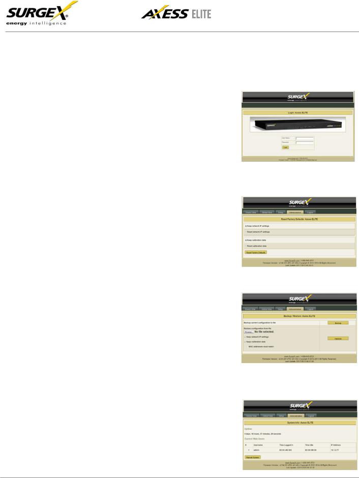
5.1Login
The Login page is the first page displayed when a web browser makes a connection to the Axess Elite. Enter a valid user name and password in the “User Name” and “Password” fields, and press “Login” to log in to the Axess Elite.
A mobile login page is available at IPAddress/mobile_login.html
5.2Administration
5.2.1Reset Factory Defaults
•Allows resetting of factory defaults from the web interface.
•Options to keep or reset network IP settings.
•Options to keep or reset calibration data.
5.2.2Backup/Restore
•Provides Configuration Management via *.conf files.
•Backup current configuration to file.
•Restore configuration from previously saved file.
-Option to keep current network IP settings or use those in configuration file.
-Option to keep current calibration data or use calibration values in configuration
file.
·If restoring the calibration values
stored in a configuration file, there is an option to only restore the values if the MAC address
of the unit and the MAC address in the configuration file match.
5.2.3System Info
•Displays number of logged in web users, time each user has been logged in, and System uptime. Also provides a Reboot button
© 2015 SurgeX/Electronic Systems Protection, Inc. | Technical Support: 800-645-9721 | surgex.com |
9 |
User Manual
Firmware Version v2.04.281
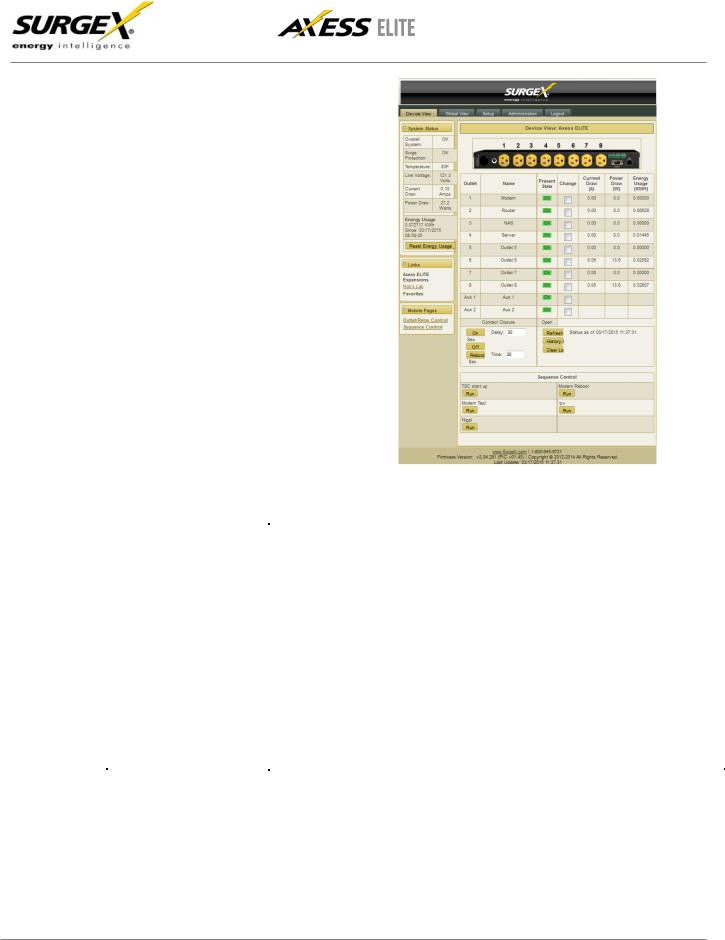
5.3Device View
The Device View page provides information and status for the whole unit and individual outlets, as well as basic control of outlets. The top left section of the page provides system status. To refresh the status information, click the
“Refresh” button.
For each outlet the Outlet Name,
Present State, Current Draw, Power
Draw, and Energy Usage are displayed.
Mobile Page links are at the bottom left below the Links section.
Contact Closure input status is displayed.
Device View |
|
Item |
Description |
Overall System |
Indicates that the surge protection, rack temperature, line voltage, and |
|
current draw are at acceptable levels. |
Surge Protection |
Indicates that the surge protection is fully functional. |
Rack Temperature |
Displays the temperature of the sensor that is connected to the rear terminal |
|
block. If the temperature sensor is not connected, the display will read “NC” |
|
|
Line Voltage |
Displays the true-RMS AC voltage. |
Current Draw |
Displays the total current draw of all 8 receptacles in true-RMS Amps. |
Power Draw |
Displays the total power draw of all 8 receptacles in Watts. |
Energy Used |
Displays the total energy consumption of the equipment plugged into the |
|
unit in KWHours since the last counter reset. Pressing “Reset Energy |
|
Usage” will reset the KWHours count. |
On |
Turns the selected outlets on, staggered by the Delay time. |
Off |
Turns the selected outlets off. |
Reboot |
Turns the selected outlets off for the length of the Reboot Time, and then back on. |
|
|
History Log |
Displays the internal history log (if enabled). |
© 2015 SurgeX/Electronic Systems Protection, Inc. | Technical Support: 800-645-9721 | surgex.com |
10 |
User Manual
Firmware Version v2.04.281
5.4Global View
The Global View page displays the current outlet states and system status for the Axess Elite and expansion units. Up to 15 expansion units may be set up on the Links Setup page.
Outlets and Aux Relays may be commanded to turn On, Off, or Reboot for up to 16 Axess Elite units (1 master and 15 expansions).
In order to have rights to control expansion unit outlets, the user’s identical user name and password must be programmed into each expansion Axess Elite to be managed.
5.5Setup
Complete setup and configuration of the Axess Elite is provided via 7 Setup web pages. Each setup page is described in the following sections.
Setup |
|
|
|
||
Setup Page |
Description |
|
|
|
|
Device |
Configure basic device parameters |
|
Network |
Configure network settings, including the network adapter, email, and time keeping |
|
|
|
|
Network Reporting |
Configure SNMP, SDxP, and Syslog reporting |
|
Users |
Configure user accounts |
|
Triggers |
Configure System Triggers |
|
Create and modify User Triggers |
||
|
||
|
|
|
Sequences |
Create and modify custom Sequences |
|
Links |
Create and modify Expansion units and Favorite links |
© 2015 SurgeX/Electronic Systems Protection, Inc. | Technical Support: 800-645-9721 | surgex.com |
11 |
Loading...