

Page 1

User Manual
2017 AMETEK Electronic Systems Protection / Technical Support: 1-800-645-9721 / surgex.com / UM-MultiPak-Rev-B 0
SX-DS-154 / SX-DS-156
User Manual
120V Firmware Revision 1.67 and higher
Software Revision 4.0 and higher
Page 2

User Manual
© 2017 AMETEK Electronic Systems Protection / Technical Support: 1-800-645-9721 / surgex.com 1
Page 3

User Manual
© 2017 AMETEK Electronic Systems Protection / Technical Support: 1-800-645-9721 / surgex.com 2
I. INTRODUCTION 3
1. MODELS ............................................................................................................3
2. KEY FEATURES ..................................................................................................3
3. TECHNICAL SUPPORT.........................................................................................3
II. INSTALLATION INSTRUCTIONS 4
1. INSTALLATION ....................................................................................................4
III. HARDWARE 5
1. MULTIPAK .......................................................................................................5
A. NORMAL OPERATION ..................................................................................5
B. WIRING FAULT ............................................................................................5
C. ABNORMAL VOLTAGE ..................................................................................5
D. CLEARING MEMORY....................................................................................5
IV. SOFTWARE INSTALLATION 6
1. COMPUTER REQUIREMENTS ...............................................................................6
2. HARDWARE REQUIREMENTS ...............................................................................6
3. DOWNLOAD AND INSTALL SOFTWARE ..................................................................6
4. INSTALL DATA INTERFACE CABLE ........................................................................7
V. USING THE SOFWARE 7
1. PHYSICAL CONNECTIONS ..................................................................................7
2. START THE SOFTWARE ......................................................................................7
3. CONFIGURE THE DATA INTERFACE CABLE AND COM PORT ...................................8
4. SOFTWARE MODES .......................................................................................... 10
A. MULTIMETER MODE .................................................................................. 11
B. CHART MODE ........................................................................................... 12
C. OUTLET CONTROL MODE .......................................................................... 13
D. HISTORICAL DATA MODE .......................................................................... 14
E. SETTINGS MODE ...................................................................................... 16
F. COM PORT SETUP MODE .......................................................................... 17
5. COMMAND LINE OPERATION ............................................................................. 17
VI. TROUBLESHOOTING 18
1. MULTIPAK ..................................................................................................... 18
2. Software......................................................................................................... 18
VII. SPECIFICATIONS 19
Page 4

User Manual
© 2017 AMETEK Electronic Systems Protection / Technical Support: 1-800-645-9721 / surgex.com 3
I. INTRODUCTION
The MULTIPAK is a state-of-the-art power protector/power conditioner engineered with real-time data acquisition
and storage.
1. Models: This manual applies to the following MULTIPAK models:
2. Key Features:
• Multi-Stage power protection technology
• Normal and Common Mode EMI Noise Filter
• Zero-Voltage Turn-On
• Zero-Current Turn-Off
• Inrush Current Elimination (ICE
®
)
• Wiring Fault Detection
• Catastrophic over/under Voltage Shutdown (COUVS
®
) with selectable thresholds
• Under Voltage Event Recorder (up to 999 events)
• Over Voltage Event Recorder (up to 999 events)
• Power Outage Event Recorder (up to 999 events)
• Surge Event Recorder (up to 999 events)
o Records surges in all three modes: Line-Neutral, Line-Ground, Neutral-Ground
• Event Timestamp Recorder (up to 60 events)
o Records time between events
• Additional features available when connected to a PC
(detailed in Section V: Using the Software)
3. Technical Support:
• To download software and access further product information, visit http://espsurgex.com/product/multipak/
• For technical support, please contact SurgeX at 1-800-645-9721
Model Number
Voltage (AC RMS)
Current (AC Amps)
Receptacles
Input
Output
SX-DS-154
120
15
4
NEMA 5-15P
NEMA 5-15R
SX-DS-156
120
15
6
NEMA 5-15P
NEMA 5-15R
Page 5
User Manual
© 2017 AMETEK Electronic Systems Protection / Technical Support: 1-800-645-9721 / surgex.com 4
II. INSTALLATION INSTRUCTIONS
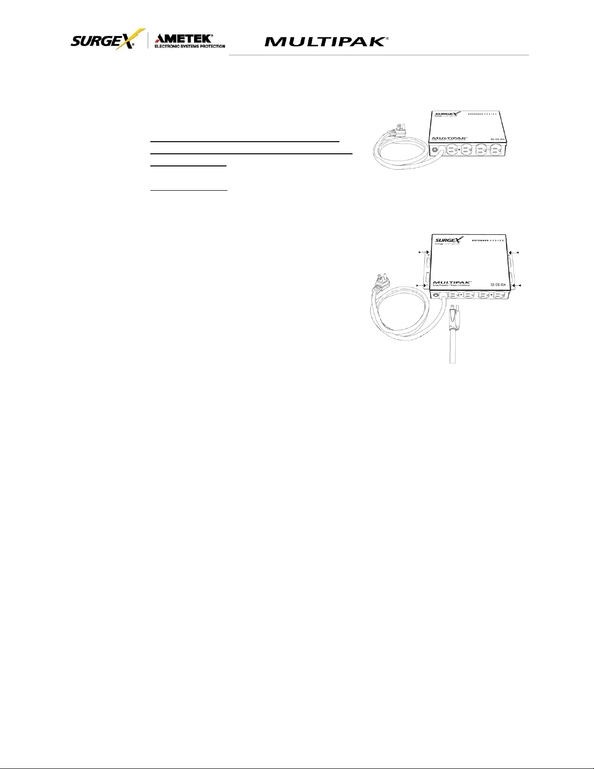
1. Installation:
a. Turn off the equipment you are connecting to the
MULTIPAK, and unplug the equipment’s power cord
from the wall outlet.
b. Connect Equipment
Connect the AC power cord of the equipment to be protected into one of the MULTIPAK
convenience receptacles. Make sure that the total amperage of all equipment plugged into
the MULTIPAK does not exceed the maximum branch circuit rating.
Please Note: Exceeding the branch circuit rating will
cause the branch circuit breaker to trip.
c. Connect the MULTIPAK to the Outlet: Plug the MULTIPAK input power cord into a properly
grounded and compatible branch circuit outlet.
Please Note: Do not plug the MULTIPAK into a relocatable power tap.
i. If the branch circuit outlet is correctly wired and the magnitude of the line voltage is
acceptable, between 105 and 130 V
RMS
, power will be connected to the outlets of the
MULTIPAK and the Green “System On” LED will illuminate. Your equipment is now
protected and installed correctly. You may now turn all connected equipment back on.
ii. If the branch circuit outlet is incorrectly wired, the “Red Wiring Fault” LED will illuminate. If
this occurs, contact a licensed electrician to correct the outlet wiring. Refer to Section III.1:
Hardware/MULTIPAK
iii. If neither “System On”, nor the “Wiring Fault” LED illuminates, there is either no voltage at
the receptacle or the magnitude of the line voltage is not acceptable (less than 105 VRMS
or above 130 VRMS). If this occurs, verify that the MULTIPAK is operating properly. To
test, plug the MULTIPAK into a known properly functioning outlet. If the “System On” LED
still does not illuminate in the functioning outlet call SurgeX at 1-800-645-9721. If the
“System On” LED illuminates, contact a licensed electrician to troubleshoot the abnormal
voltage condition.
Page 6

User Manual
© 2017 AMETEK Electronic Systems Protection / Technical Support: 1-800-645-9721 / surgex.com 5
III. HARDWARE
1. MULTIPAK:
a. Normal Operation
Plug the MULTIPAK input power cord into a properly grounded and compatible branch circuit outlet;
the green “System On” LED will illuminate.
b. Wiring Fault
When connected to an incorrectly wired branch circuit outlet, the Red LED will be illuminated.
c. Abnormal Voltage
When the magnitude of the branch circuit outlet voltage is not acceptable*, the MULTIPAK will
disconnect power to its outlets; refer to Section IV: Diagnostic Software for more information).
d. Clearing Memory
The MULTIPAK is able to timestamp the 60 most recent power quality events (information stored in
microcontroller non-volatile memory). The microcontroller memory contents can be cleared at any
time by following this method:
i. Diagnostic Software:
The device microcontroller memory may be cleared from within the Diagnostic Software in
the following location: “Tools/Clear Device Memory”. See Section V for details.
Page 7
User Manual
© 2017 AMETEK Electronic Systems Protection / Technical Support: 1-800-645-9721 / surgex.com 6
IV. SOFTWARE INSTALLATION
1. Computer Requirements
a. Minimum 133MHz Pentium processor (or equivalent), minimum 64MB of RAM,
minimum 10MB free hard drive space, VGA or higher resolution monitor,
keyboard, mouse, CD or DVD drive, minimum screen resolution of 1024x768,
Microsoft Windows XP/Vista/7/8/10.
2. Hardware Requirements
a. For use with enVision enabled products and Data Interface Cable (XG-PCS-1C-1)
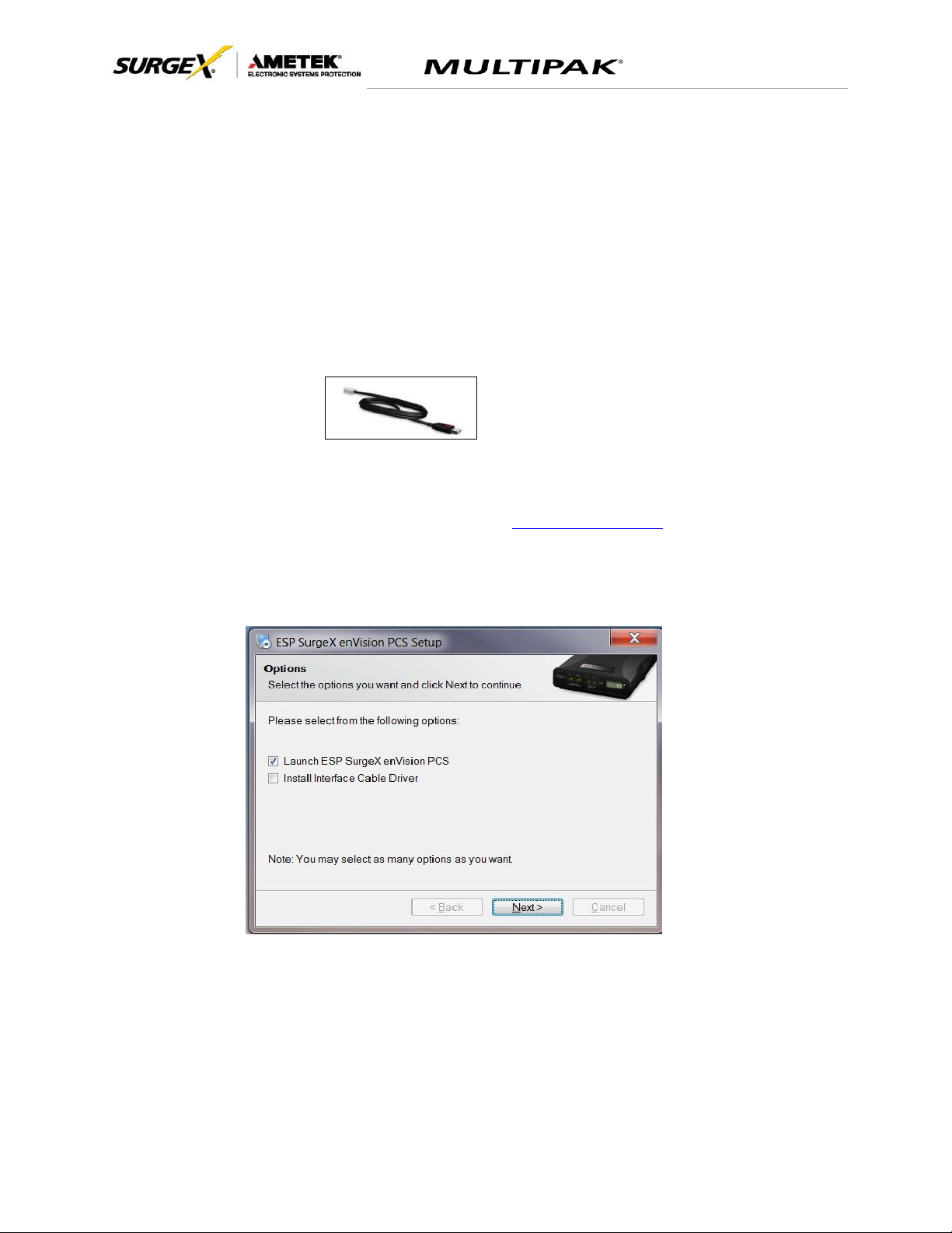
3. Download and Install Software
a. Download the Software Installer from www.espsurgex.com
b. Unzip and run the installation utility.
c. Follow the on-screen instructions to complete installation of the software.
Page 8

User Manual
© 2017 AMETEK Electronic Systems Protection / Technical Support: 1-800-645-9721 / surgex.com 7
4. Install Data Interface Cable
a. Automatic Installation (Requires Internet connection)
i. Plug the USB side of the Data Interface Cable into an available USB port.
ii. Windows will automatically detect and install appropriate device driver
files for the Data Interface Cable.
•
If a “Found New Hardware” pop-up box appears, follow the on-
screen instructions and allow Windows to search online for driver
files.
•
The installation could take several minutes to search for and
download appropriate driver files. Once the files are found, follow
the on-screen instructions to install.
•
Note: The driver installation process will first install USB Serial
Converter driver files, and then will install USB Serial Port drivers
separately.
b. Manual Installation
In the event that the automatic driver installation process was not successful, or if
no internet connection is available, the Data Interface Cable driver files may be
installed manually.
•
Select “Install Drivers” during the Software Installation process.
•
Or run “Interface Setup” from: Start/All Programs/ESP
SurgeX/Diagnostic Tool
c. Once the Data Interface Cable has been successfully installed, it will appear
in Device Manager as “USB Serial Port (COMx)” under “Ports (COM & LPT)”.
V. USING THE SOFTWARE
1. Physical Connections
a. Plug the USB side of the Data Interface Cable into an available USB port.
b. Plug the RJ-11 side of the Data Interface Cable into the RJ-11 “OUT” jack
labeled “Data Port” on the unit, which is the jack closest to the
LCD.
2. Start the Software
a. Double-click the desktop shortcut labeled “ESP SurgeX
Diagnostic Tool”, or use the “ESP SurgeX Diagnostic Tool”
Start Menu short cut located at:
Start/All Programs/ESP SurgeX/Diagnostic Tool
Page 9
User Manual
© 2017 AMETEK Electronic Systems Protection / Technical Support: 1-800-645-9721 / surgex.com 8
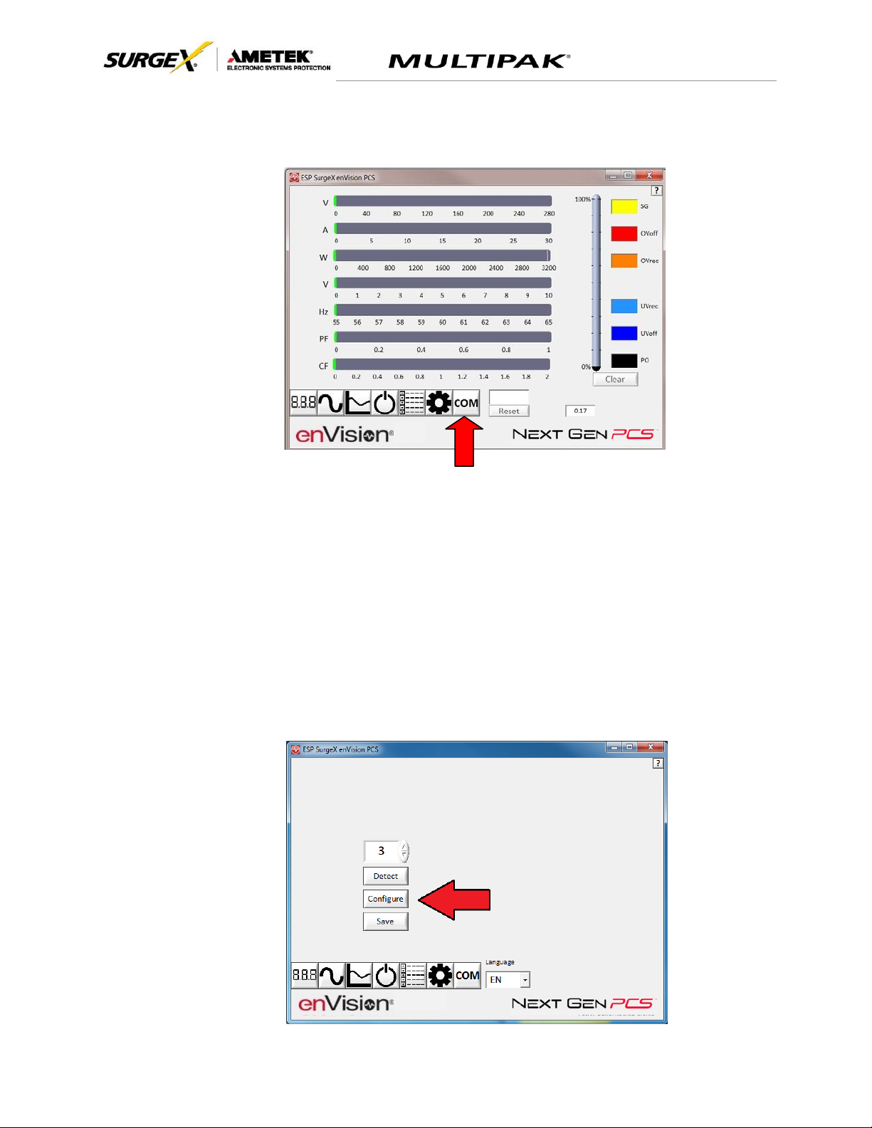
3. Configure the Data Interface Cable and COM Port
a. Click the COM Port Setup button labeled COM.
b. Click Configure.
i. The auto configuration process will automatically set the correct device
parameters of the Data Interface Cable to operate properly with the
software and Next Gen.
•
Note: This process only needs to be done once for each new
Data Interface Cable installed on the PC.
•
Note: This process edits Windows registry values, and so may be
blocked by MS Windows User Account Control (UAC) in Windows
Vista/7/8/10. It may be necessary to exit the software and restart it
with administrative rights by right-clicking the software shortcut
and choosing “Run As Administrator”. It may also be necessary to
run the compatibility wizard by right-clicking the shortcut, selecting
“Troubleshoot Compatibility”, and following the prompts.
Page 10

User Manual
© 2017 AMETEK Electronic Systems Protection / Technical Support: 1-800-645-9721 / surgex.com 9
ii. The COM port may also be manually configured using the Device Manager:
1. Open Device Manager
a. Click on Start button
b. Type the following command in the Search box: devmgmt.msc
c. Press Enter
2. In the Device Manager, expand “Ports (COM & LPT)”
3. Right-click on the entry labeled “USB Serial Port (COMx)” and click
“Properties”
4. In the USB Serial Port Properties pop-up box, click the “Port Settings” tab,
and then click the “Advanced” button.
5. In “USB Transfer Sizes”, change both the “Receive” and “Transmit”
values to 4096.
6. In “BM Options”, change the “Latency Timer” value to 2.
7. Leave all other settings at default.
+
Page 11

User Manual
© 2017 AMETEK Electronic Systems Protection / Technical Support: 1-800-645-9721 / surgex.com 10
c. Click Detect.
i. The auto detect process will automatically detect the COM Port number
assigned to the Data Interface Cable.
ii. If the auto detection process is successful, click Save. The software is
now properly configured and ready for use.
iii. If the auto detection process is not successful, verify that the Data
Interface Cable device drivers are properly installed, and that the physical
connections between the enVision and the PC have been made correctly.
d. The language may also be selected in this mode.
4. Software Modes
The Next Gen software is organized into several operational modes. The modes are
activated by clicking the corresponding button at the bottom of the software interface.
Note: Some features are only available when used with an enVision PCS product.
Press the Help Button (“?”) in the upper right for additional information on the features
available in the current mode. Hovering the mouse cursor over items will also display
additional information.
Scope Mode, Chart Mode, Historical Data Mode, and Settings Mode
include a Save function. Press the Save button to save data to a CSV file.
Time Stamped data may also be saved as a report in PDF format.
Chart Mode and Historical data may be analyzed by an automatic Expert
Analysis tool. Press the Expert button to perform an expert analysis of
recorded time-stamped event data or chart measurements and generate a
PDF report of potential conclusions and recommendations.
Page 12

User Manual
© 2017 AMETEK Electronic Systems Protection / Technical Support: 1-800-645-9721 / surgex.com 11
a. Multimeter Mode
i. The Multimeter Mode provides information traditionally acquired from a
handheld digital multimeter, as well as an overview of the recorded power
quality events. ±2% Typical Measurement Accuracy.
Page 13

User Manual
© 2017 AMETEK Electronic Systems Protection / Technical Support: 1-800-645-9721 / surgex.com 12
ii. Real-time display of electrical parameters
•
Line Voltage: AC RMS Volts. Peak Measurement Type
•
Neutral-Ground Voltage: AC RMS Volts Neutral-Ground. Peak
Measurement Type. Available with 120V models with firmware
version 2.00 and later. ±1V accuracy from 3V-10V.
iii. Number of recorded power quality events
•
Surge Events: SG
•
Overvoltage Events: OVrec
•
Undervoltage Events: UVrec
•
Power Outage Events: PO
b. Chart Mode
i. The Chart Mode enables a chart style data logging function of electrical
parameters. Data point measurements are acquired once per second.
The measured parameters may be enabled or disabled by pressing the
corresponding button.
ii. Chart display of electrical parameters:
•
Line Voltage: AC RMS Volts. Peak Measurement Type
•
Neutral-Ground Voltage: AC RMS Volts Neutral-Ground. Peak
Measurement Type. Available with 120V models with firmware
version 2.00 and later. ±1V accuracy from 3V-10V.
Page 14

User Manual
© 2017 AMETEK Electronic Systems Protection / Technical Support: 1-800-645-9721 / surgex.com 13
c. Outlet Control Mode
i. The Outlet Control Mode enables control of the AC outlets and provides
information about wiring faults and abnormal line voltage.
ii. Use the green On/Off button to manually turn the AC outlets on and off.
•
Pressing the blue Power Cycle button will result in the execution
of a power cycle. When commanded, the outlets will turn off, and
then back on, after a 90 second delay. The Power Cycle
indicator will be illuminated while a power cycle is active.
Page 15

User Manual
© 2017 AMETEK Electronic Systems Protection / Technical Support: 1-800-645-9721 / surgex.com 14
d. Historical Data Mode
The Historical Data Mode allows for the retrieval and display of the power quality
event data stored in the Next Gen internal memory.
i. Time Stamped Power Quality Event Data
▪ Next Gen is able to store and timestamp the 60 most recent
power quality events in its internal memory. Press the Import
Time Stamped Data button to download the event data.yuikl
Page 16
User Manual
2017 AMETEK Electronic Systems Protection / Technical Support: 1-800-645-9721 / surgex.com / UM-MultiPak-Rev-B 15
Four types of events are logged:
▪ Surge: Next Gen has been exposed to a transient voltage in one
of the 3 possible modes (between Live and Neutral, between Live
and Ground, between Neutral and Ground) with a peak amplitude
of 500V* or higher and a frequency of 20 kHz or higher. *500V
surge voltage amplitude applies to IEEE C62.41 Category B
Impulse; surge voltage amplitudes necessary for detection of other
surge types may vary.
▪ Over Voltage: Line voltage exceeded the over voltage record
threshold.
▪ Under Voltage: Line voltage dropped below the under voltage
record threshold.
▪ Power Outage: Loss of AC power.
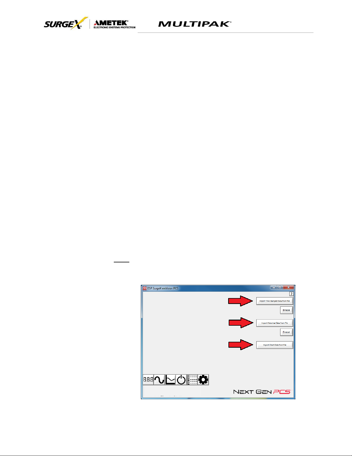
ii. Import Data
Previously saved data files may be imported by entering the Historical Data
Mode while no product is connected. This may be achieved by removing the
data interface cable or by selecting and saving an invalid COM Port number.
Press the button that corresponds to the type of data file to import and browse
to the location of the file.
Note: “Import Historical Data from file” applies to enVision PCS, not Next Gen
PCS.
Page 17
User Manual
© 2017 AMETEK Electronic Systems Protection / Technical Support: 1-800-645-9721 / surgex.com 16
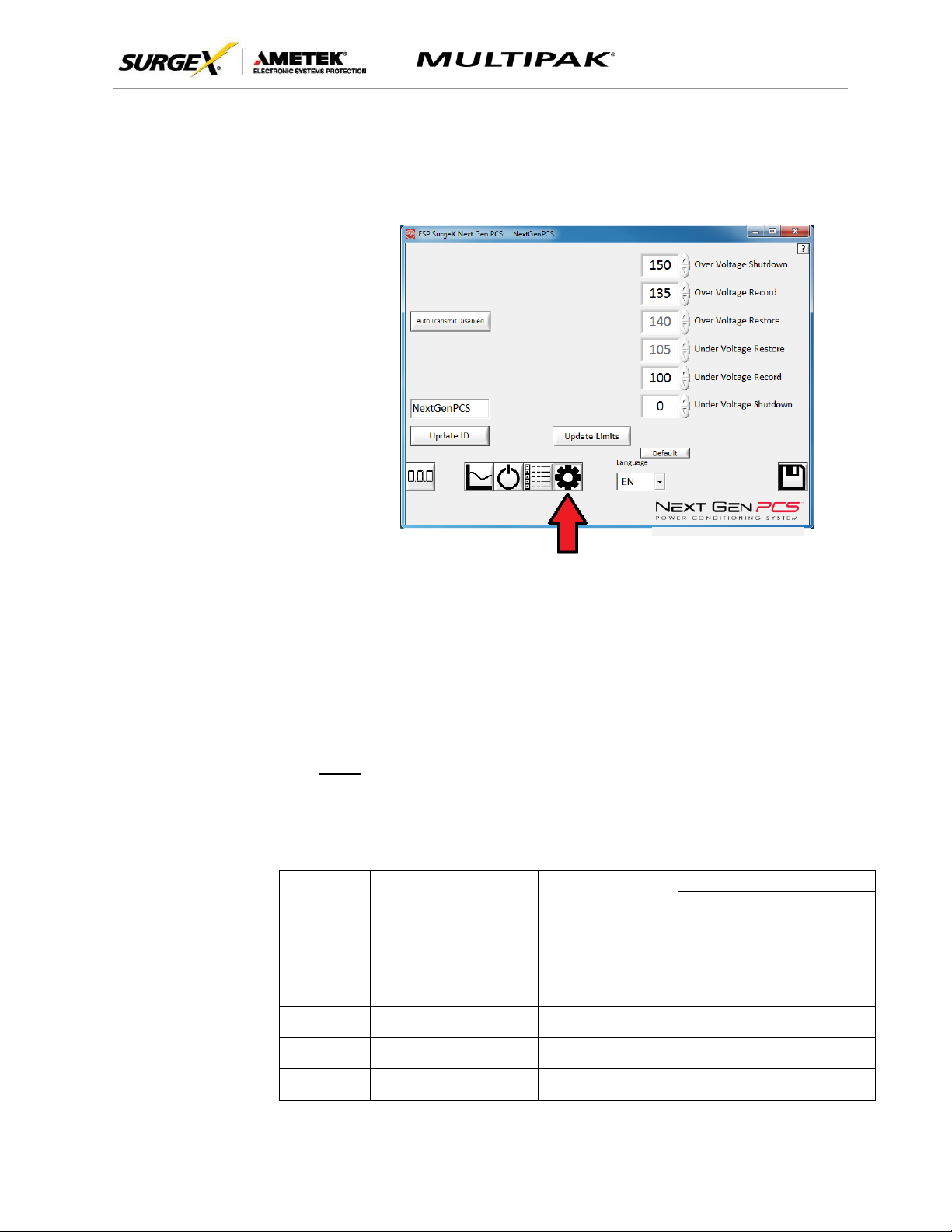
e. Settings Mode
The Settings mode enables the specification of the user-configurable
parameters of Next Gen. When this mode is entered, it displays the
parameters currently in use. Firmware versions prior to 1.53 (120V models)
and 1.02 (208-240V models) do not support the Auto Transmit feature.
i. Auto Transmit: Enables/Disables the automatic transmission of status
information every 30 minutes. Primarily intended for use with Remote
Portal RP-IP.
ii. Update ID: Sets the product identifier specified in the text box. 10
character limit. This is a temporary setting intended to set an ID for
saved reports.
iii. Update Limits: Sets the voltage thresholds specified by the voltage
threshold selection fields. Press Default to select factory default limits.
Note: Restore points may not be specified for Next Gen PCS.
x. Language: Select the software’s display language.
xi. Save: Save the current settings for reference.
Limit
When Activated
Action
Factory Default
120V
208/240V
Over Voltage
Shutdown
V > OV
Shutdown
Outlets turned Off and
event recorded
150
260
Over Voltage
Record
OV
Shutdown
> V > OV
Record
Outlets stay On and
event recorded
135
260
Over Voltage
Restore
V < OV
Restore
After OV
Shutdown
Outlets turned On
140
250
Under Voltage
Restore
V > UV
Restore
After UV
Shutdown
Outlets turned On
105
190
Under Voltage
Record
UV
Shutdown
< V < UV
Record
Outlets stay On and
event recorded
100
180
Under Voltage
Shutdown
V < UV
Shutdown
Outlets turned Off and
event recorded
0
(Disabled)
140
Page 18

User Manual
© 2017 AMETEK Electronic Systems Protection / Technical Support: 1-800-645-9721 / surgex.com 17
f. COM Port Setup Mode
i. The COM Port Setup mode is used to configure new Data Interface
Cables for use.
ii. Detect: Automatically detect the COM Port when the Next Gen, Data
Interface Cable, and PC are properly connected and powered up.
iii. Configure: Automatically configure the advanced settings of the Data
Interface Cable. May require running the software with elevated
permissions (right-click program shortcut and choose “Run As
Administrator”) on Windows Vista/7/8/10 with UAC (User Account
Control) enabled.
iv. Save: Saves the COM Port selection.
5. Command Line Operation
Usage: ESP_SurgeX_Diagnostic_Tool (/o output_file) [-a] [-t] [-c] [-m]
Example : ESP_SurgeX_Diagnostic_Tool /o C:\Users\Robert\Desktop\log.txt -a -m
Option
Meaning
-a
Append output file. If output file already exists, column headers will not be
written.
-t
Write Timestamped data.
-c
Write Event Counts.
-m
Write Measurements.
If neither -t, -c, nor -m is specified, all will be written.
If -a is not specified, output file will be overwritten.
Page 19
User Manual
© 2017 AMETEK Electronic Systems Protection / Technical Support: 1-800-645-9721 / surgex.com 18
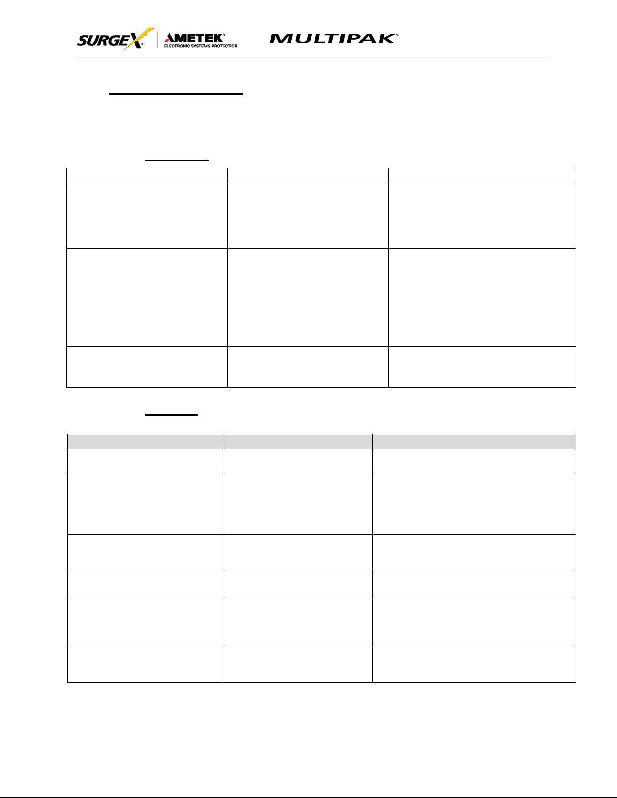
VI. TROUBLESHOOTING
The MULTIPAK and Data Interface Cable contain no user-serviceable parts. Do not attempt product
disassembly, as this will void the product warranty.
1. MULTIPAK:
Symptom
Possible Cause
What to Do
Red LED On, Green LED Off, No power at
output
Incorrectly wired branch circuit outlet
Contact a licensed electrician to correct the branch
circuit outlet wiring
Red LED Off, Green LED Off, No power at
output
No voltage or unacceptable voltage at
branch circuit outlet, or MULTIPAK output
manually turned Off
Use the Communications Software to measure the
voltage at the wall receptacle. Use the
Communications Software to manually turn the
outlets On. Plug the MULTIPAK into a known
properly functioning outlet. If the “System On” LED
still illuminates, contact a licensed electrician to
troubleshoot the wall receptacle. If the “System On”
LED still does not illuminate call SurgeX at
1.800.645.9721
Red LED Off, Green LED On, No power at
output
Defective product
Contact SurgeX for product replacement at
1.800.645.9721
2. Software:
Symptom/Error Message
Possible Cause
What To Do
Unable to automatically
determine COM Port
Data interface cable not
properly connected.
Check interface cable connections at PC
and XG.
COM Port not successfully
configured.
Windows User Account Control
has prevented the software
from automatically modifying
the COM Port settings in the
system registry.
Exit the software, right-click the desktop
shortcut, and select “Run As Administrator”
or select “Troubleshoot Compatibility” and
follow the wizard.
Unable to locate or read
dictionary file.
One or more language
dictionary files cannot be found
in the installation directory.
Uninstall the software, and then reinstall
the latest version.
Problem communicating with
XG.
Data interface cable not
properly connected.
Check interface cable connections at PC
and XG.
COM Port Settings are not
correct, which may result in
non-optimal operation.
The COM Port has not been
properly configured.
Configure the COM Port following the
steps listed in the Configure the Data
Interface Cable and COM Port section of
this manual.
Wrong or corrupt file.
A file import operation has
been attempted with an invalid
or corrupt data file.
Select a valid data file for import.
Page 20
User Manual
© 2017 AMETEK Electronic Systems Protection / Technical Support: 1-800-645-9721 / surgex.com 19
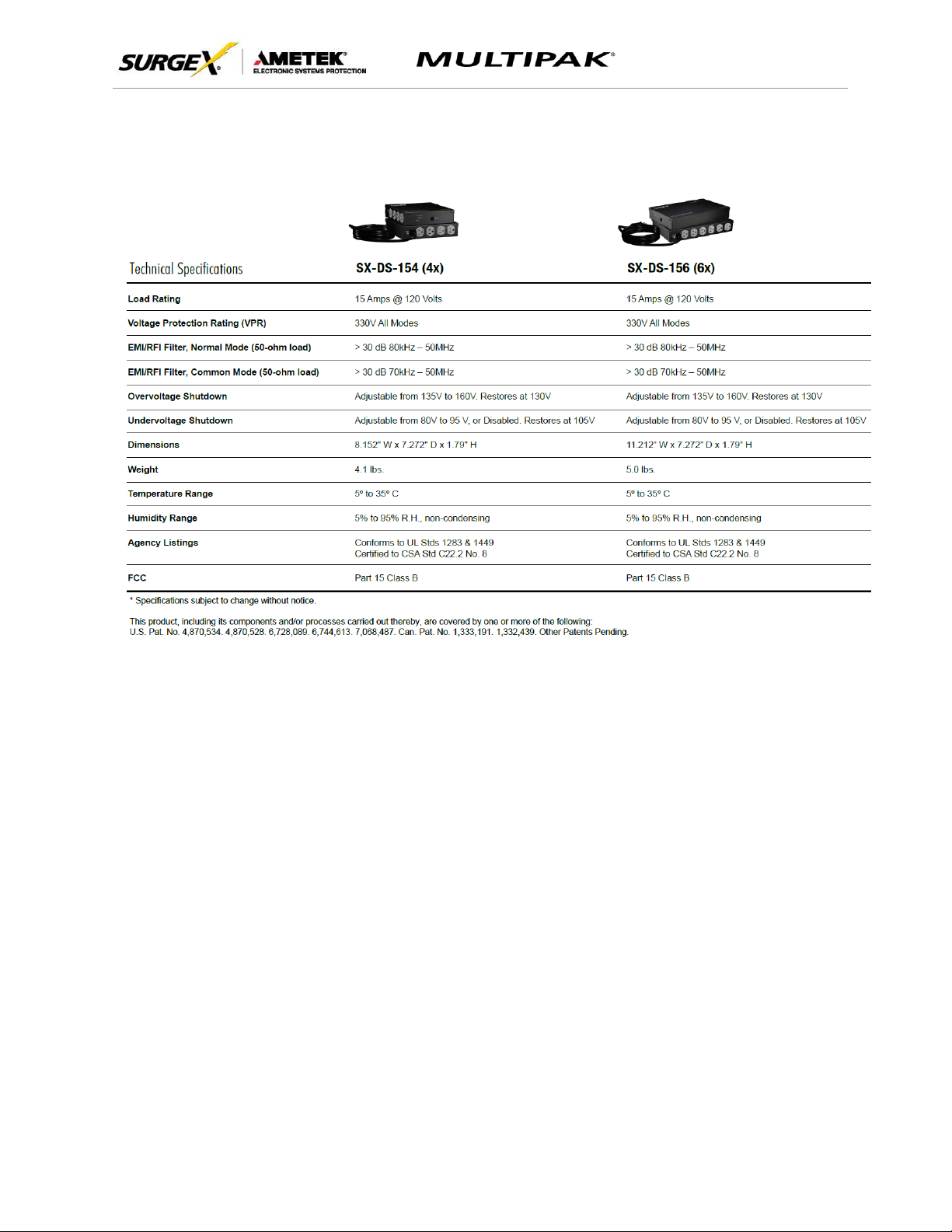
VII. Specifications
 Loading...