

Page 1
NE-MI
USER MANUAL
PLEASE READ THESE INSTRUCTIONS CAREFULLY BEFORE
INSTALLATION. LEAVE A COPY FOR THE END USER/MAINTENANCE
ENGINEER FOR FUTURE REFERENCE.
LED NEON FLEX RIBBON
ARTIST OF LIGHT
Versi on No. : V2 .0
Page 2

02
Table Of Contents
Unpacking
Basic Parameters
Cautions
Instructions for Cutting Light
Clasp Front Connector
Clasp End Cap
Snap Front Connector
Snap End Cap
Swivel Front Connector
Swivel End Cap
Diagram of Light Wiring
Mounting Profile Options
Troubleshooting
03
06
07
08
09
13
16
20
24
27
28
30
40
Limited Warranty
Appendix
USER MANUAL
41
42
www.surelight.com
Page 3
03
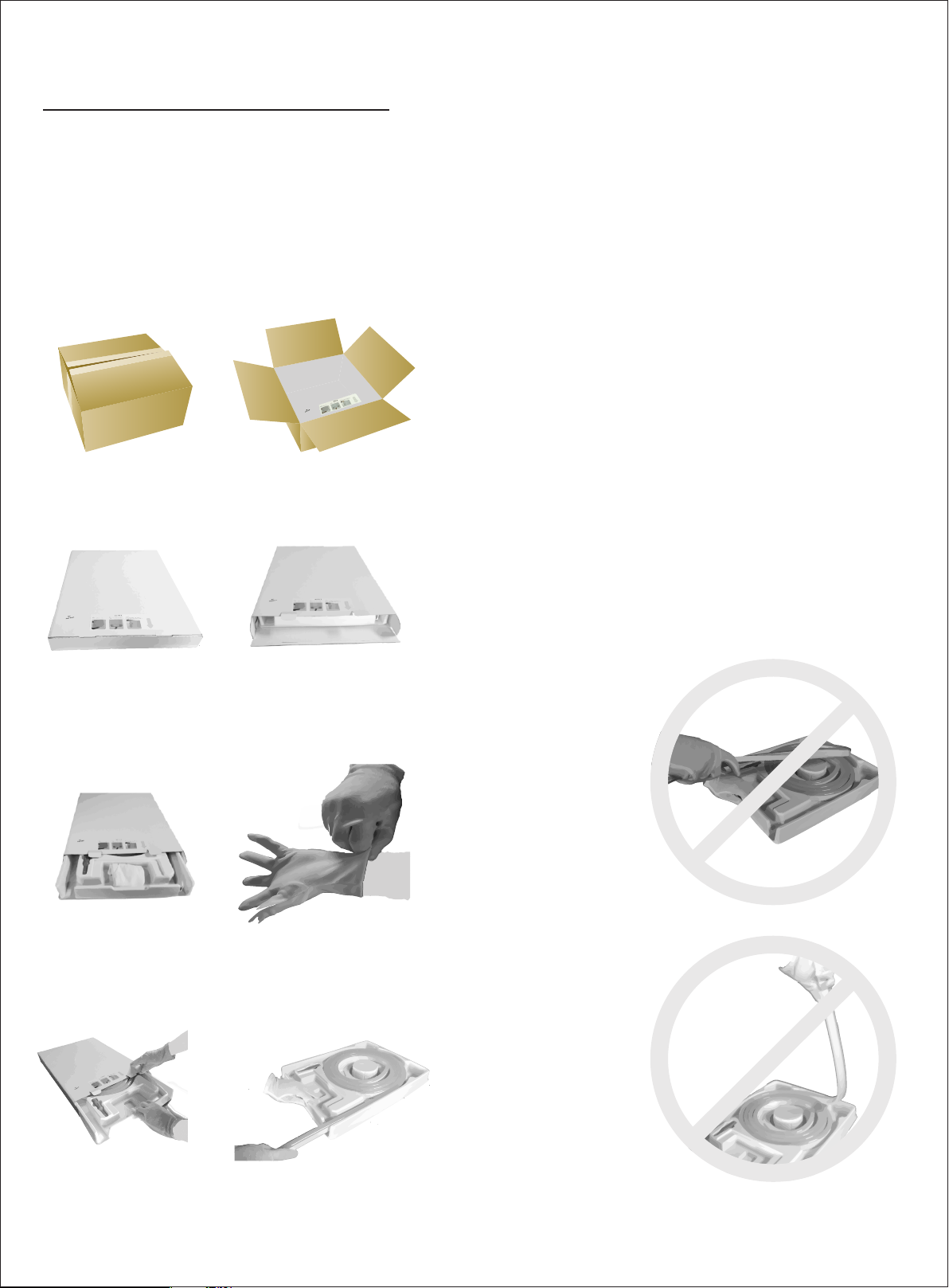
Unpacking
White Box Packaging
1 2
3
5 6
7
8
USER MANUAL
www.surelight.com
Page 4
04
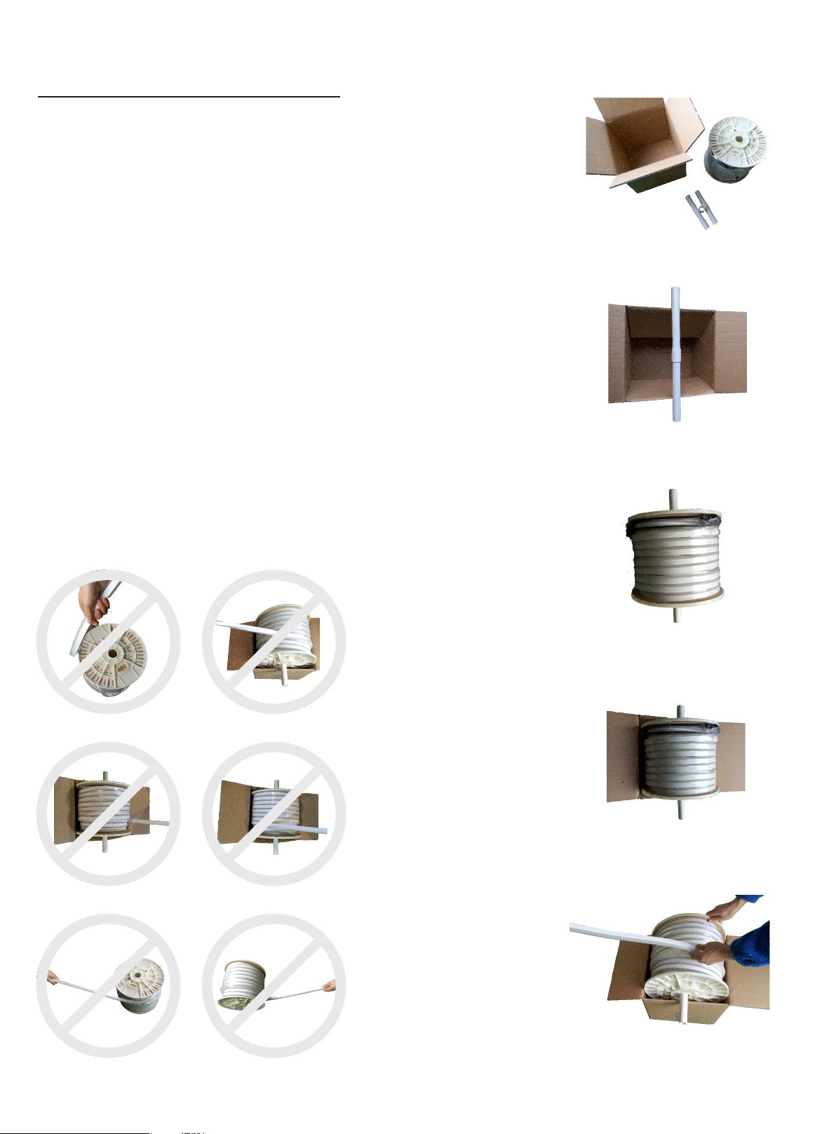
Unpacking
Reel Packaging
Note: Two pe ople are nee ded to uncoil the light.
1
2
3
4
5
USER MANUAL
www.surelight.com
Page 5
05
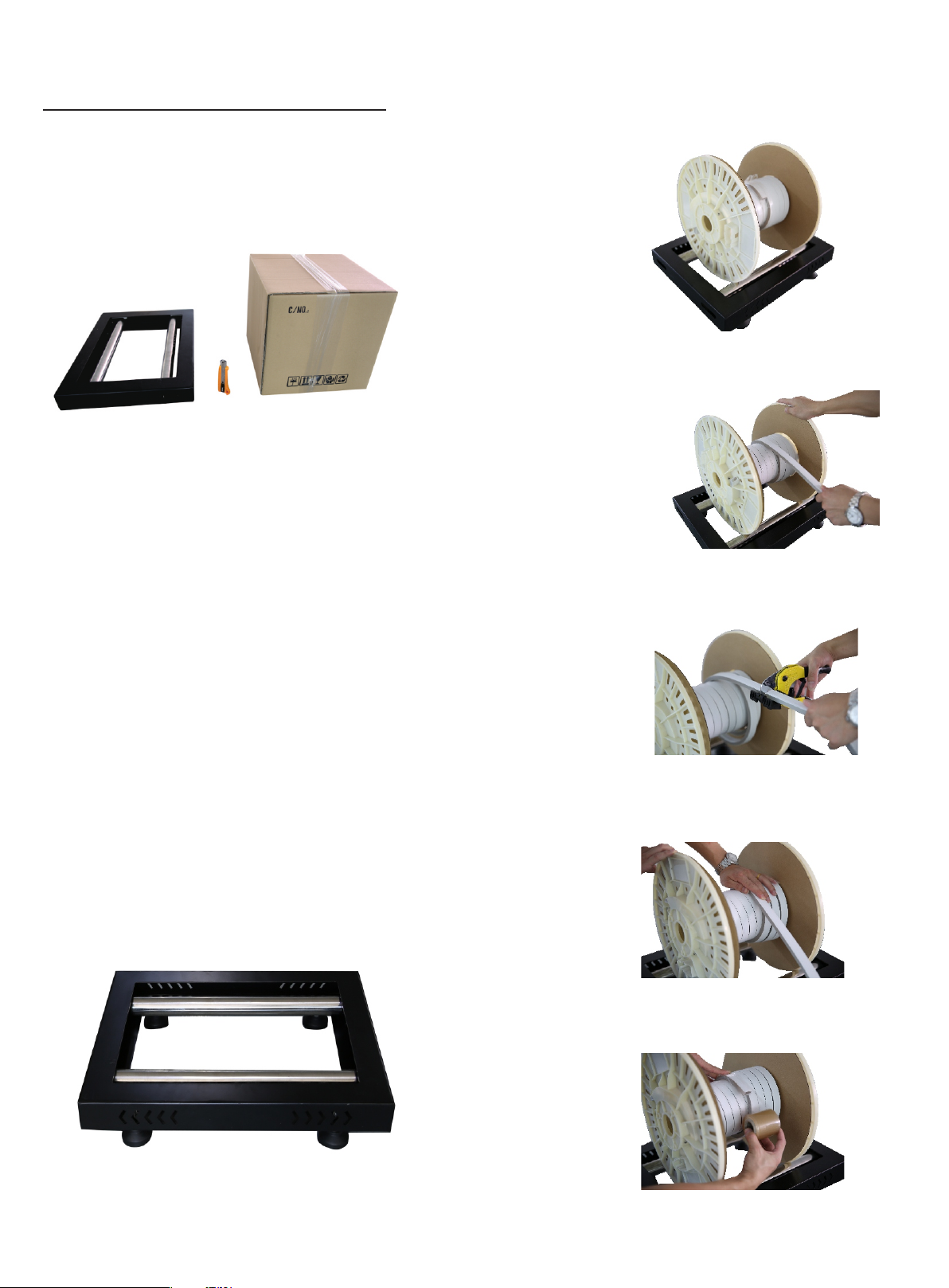
Unpacking
Uncoilin g Roller
Put t he light on the mi ddle of
uncoilin g roller
Rotate th e roller edg e to uncoil the
lig ht with another hand
Use recommended cutter to cut
the l ight vertically
Roll up the rest of the light
Uncoilin g Roller (Optional Device)
Protect the light end and fix it
USER MANUAL
www.surelight.com
Page 6
06
Basic
Parameters
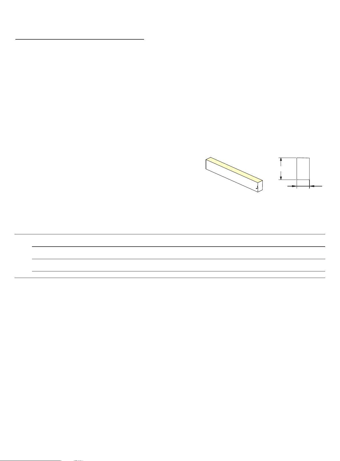
1. Di mensi on: 9*18mm
2. Mi n. bend d iameter: 90mm
3. Protection rate: I P68/I P67/I P65/I P20
4. IP 68 protection rate: Protected agains t dust an d subme rsion i n water (1 meter above) .
5.The product IP rate is ultimately in line with properl y appli ed IP rated con nectors.
Connector termination required after cutti ng to achieve appropriate IP Rat ing.
6. Ea sy to use, with a ran ge of accessories for joining, ter minating, mo unting&powering.
7. Long Iifetime : 5 years.
8. Working ambi ent temperature: - 20°C~45°C (High Voltage : -20°C~35°C ) .
9. Environmental Installation Tempeature: 0°C~ 45°C (Hig h Volt age: - 0°C~35°C ).
Note : Unles s otherwis e stated , the tol erance of the l ight is ±0 .3mm.
18mm
0
1
9mm
Light Type: NE-MI
Lig ht Color
B
NOTE: Appearance of Cover
WM= White P VC Housi ng +Mi lky Lig ht-emi tting S urfac e
Note 1 : Housi ng colo r is the li ght colo r except fro m the lig ht-em ittin g surfac e.
Note 2 : Light -emit ting su rface col or is the c olor wi thout l ight up.
R/A
G/B /W
R/A /G/B/ W
R/A /G/B/ W
App earanc e of Cover*
WM
WM
WM
WM
*
1 2
LED Q ty/mtr
72L EDs
72L EDs
72L EDs
72L EDs
Work ing Volta ge
D24 CV
D24 CV
D12 CV
Ac23 0
Rate d Power/ m
3.5 W
4.5 W
4.5 W
5W
LED S pacin g
13. 89mm
13. 89mm
13. 89mm
13. 89mm
Min .Cutti ng Leng th
125 mm(9L EDs)
83. 3mm(6 LEDs)
41. 7mm(3 LEDs)
100 0mm(7 2LEDs )
Max .Runni ng Leng th
20m fo r singl e end feed
40m fo r doubl e ends feed
15m fo r singl e end feed
30m fo r doubl e ends feed
7.5 m for sing le end feed
15m fo r doubl e ends feed
80m fo r singl e end feed
USER MANUAL
www.surelight.com
Page 7
07
Cautions
1. Before maki ng any cuts, installation, maintenance o r
connecti on, be su re the mains is disconnected!
2. Note: All connectors should be p roperly in stall ed to achieve
the a ppropriate level of IP, IP rating ca n NOT be achieved
wit hout connector termination.
3. Pl ease op erate this flex l ight by in struc tions , and conf irm the
work vol tage, i t must be m atched with product requirements.
4. Pl ease confirm the polarity of connector before inser tion front
connecti on cabl e.
5. Connect a nd cut th is product correctly. Any wrong operati on
wil l damag e this produ ct.
6. Us ing qua lifie d DC power sup ply.
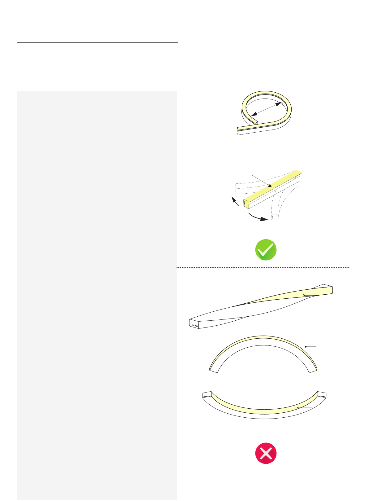
7. Pl ease correctly use and bend this flex rib bon lig ht, see the
fig ures on the ri ght.
8.D o not operate l ight when ambient temperature exceeds th e
range of specifie d temperature in User Manual.
9.D o not energize the light over 30 min utes in coil packag ing.
90 mm
02
|
01
Do not ben d small er than a llowed m inimu m bend di ameter 9 0mm.
Lig ht Surfa ce
(HB )Hori zontal B endin g
Lig ht Surfa ce
Twist the l ight
Lig ht Surfa ce
Lig ht Surfa ce
WARNING : The above wro ng appro aches w ill dam age the l ight.
USER MANUAL
www.surelight.com
Page 8
08
Instructions
for
light
cutting
Note:
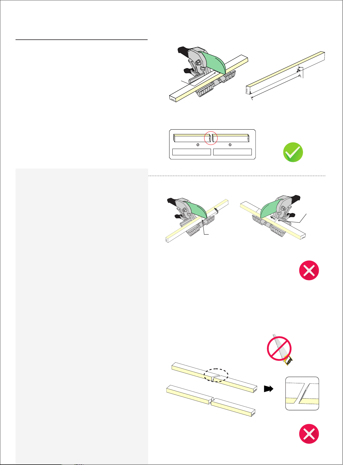
1. Pl ace the light horizontally when cutting it .
2. Use on ly facto ry-recommende d cutter.
3. Cut the light according to the fol lowing instr uctio ns.
Incorrect operation will da mage th e light
02
Cuttin g line
Cut the li ght only at pri nted cutti ng line w ith
pri nting mark face up wards
01
02
01
02
The M in. cut ting le ngth
(se e as the feat ure)
The c uttin g surface must be f lush
and s mooth.
02
01
02
01
Cuttin g
e
lin
Cutt ing lin e
Cutt ing Lin e
Prin ting Ma rk
Pri nting mark s hould b e faced
upwa rds
Ple ase use a s mooth and sh arp cut ter for cutti ng when t he dedi cated cu tter is not
avai lable , any rusty or j agged c utter i s prohib ited.
Note : Waterpr oof may not a chieve d with th e follow ing sit uation s.
Cuttin g can onl y be made at the
pri nted cut ting li ne
USER MANUAL
Don 't cut sl anting ly
www.surelight.com
Page 9
09
Clasp Front
Connector
Please ignore these steps if the front
connector has been assembled before
delivery.
Note:
1. Never wet the assembly units or as sembl e with
wet hands.
2. Pl ease us e the tools correctly.
3. Pl ease pay attention to persona l secur ity whe n
usi ng tools.
4.Repeated assembly or reus e of the connector may
result i n waterproof failure.
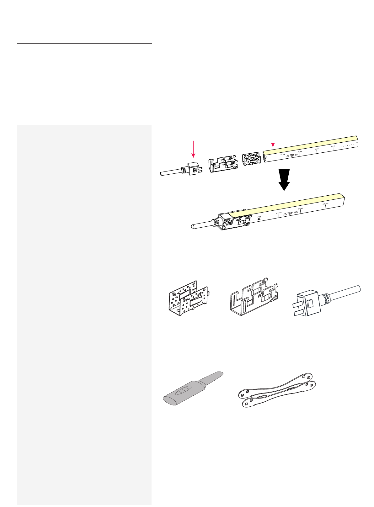
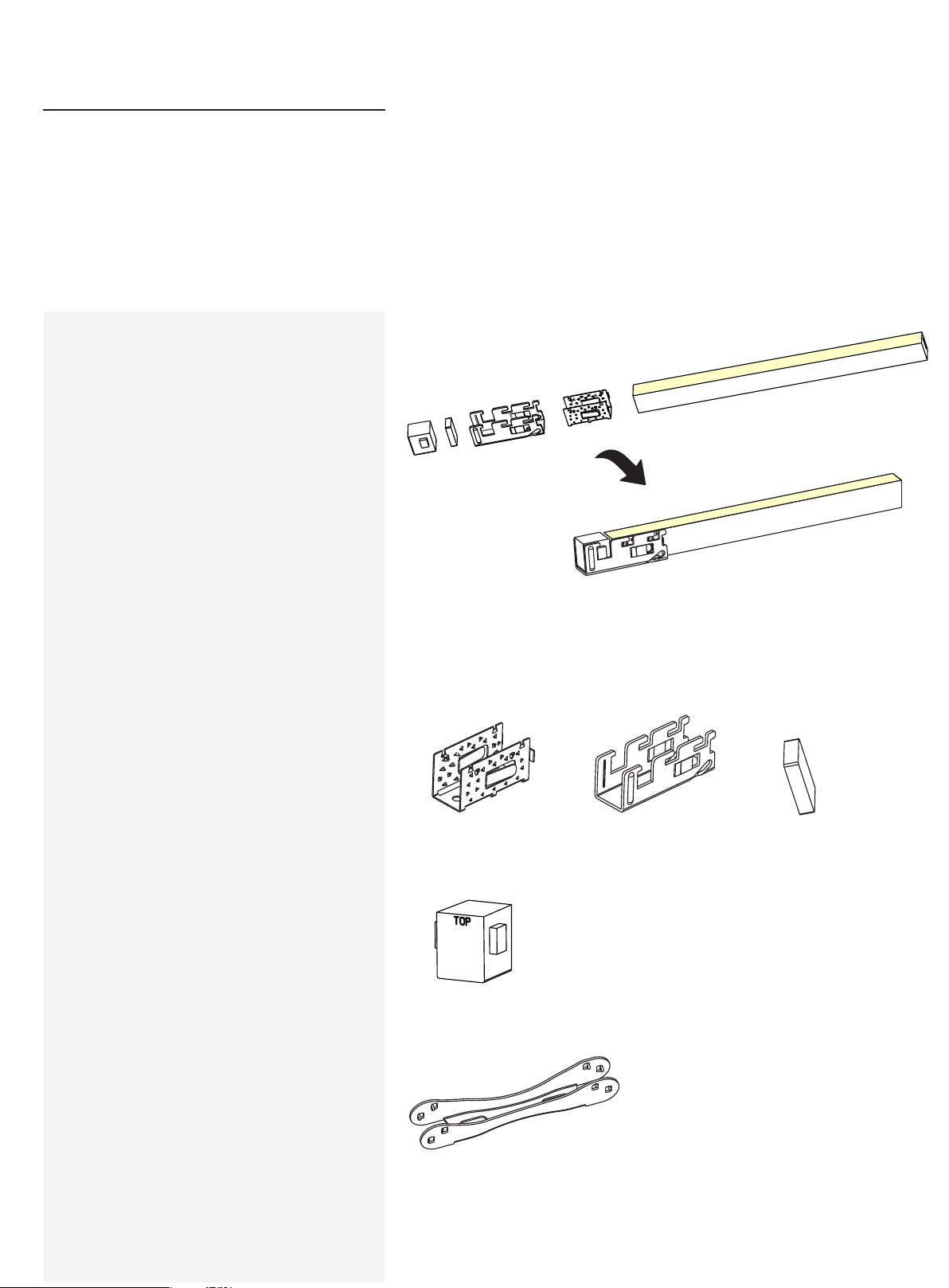
1.Components of Front
Connector
Note:
The light ends are marked with either an 01 or an 02. Always
make sure to use an identically labeled connector for the
appropriate direction.
02 Fe ed Connec tor 02 E nd of l ight
Ex plos ive View
Fi nish ed As semb ly Vi ew
Ant i-s kidd ing C lip (1p c) U Stee l Plat e (1pc)
02
Fee d Conn ecto r (1p c)
[Co ntai n Sil icon e Gas ket(1p c)]
2.Tools
In duce r Gr ippe r
USER MANUAL
www.surelight.com
Page 10
10
3.Installation Steps
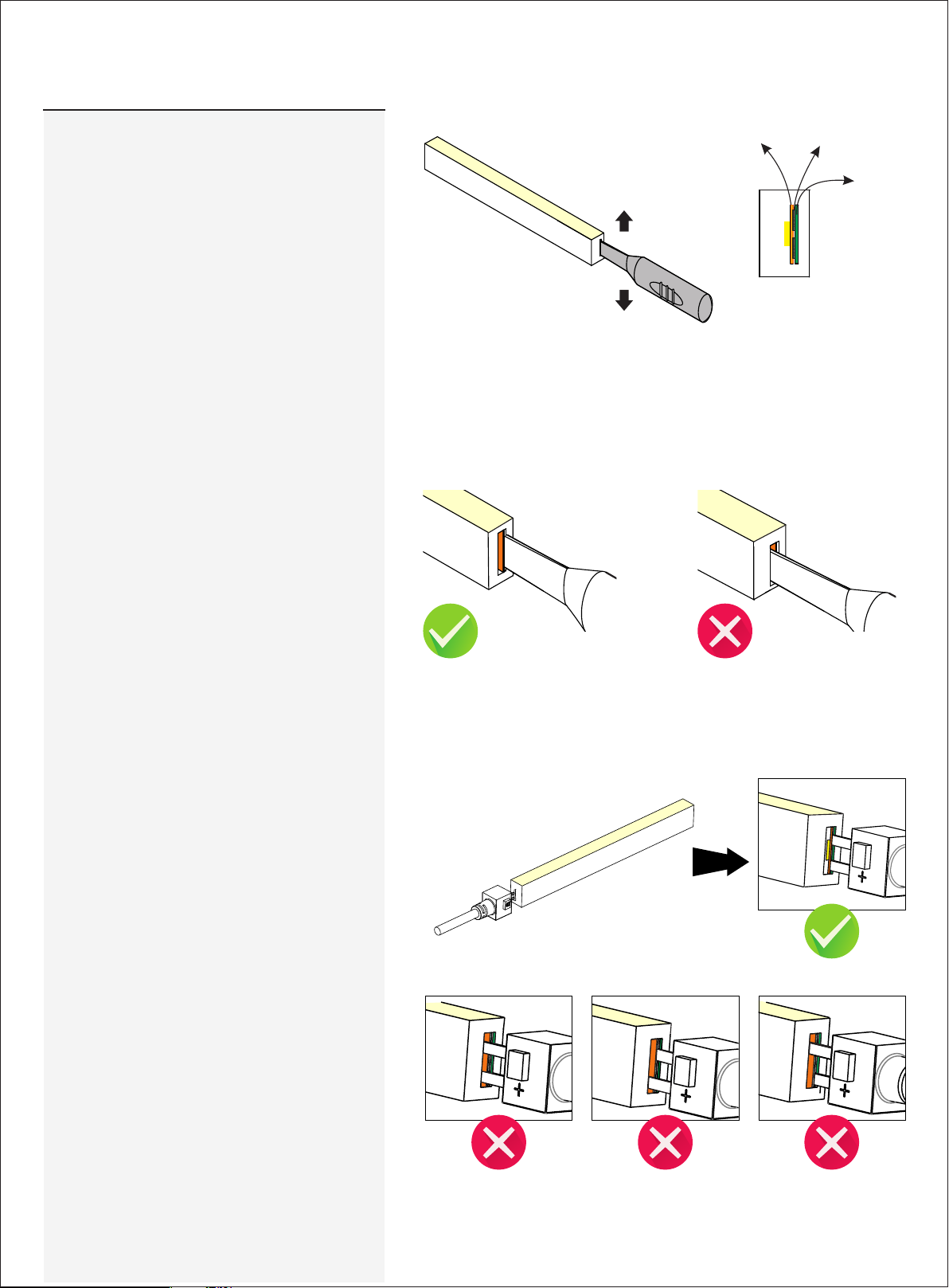
3.1 Inducing a Cavity for Feed Connector
NEV ER inse rt into the front side
(LE D side) of the PCB
In sert t he in duce r to th e backs ide of P CB around 1 0~12 mm,
mov e the i nducer up a nd dow n 3~5 t ime s gent ly to c reate a
sm all ca vity.
PCB
Ins ertio n Placem ent
PVC Tap e
3.2 Insert the Feed Connector
Insert the ind ucer into the back side of PCB
Ins ert the fee d connec tor pins i nto the
cavi ty that yo u created with t he
ind ucer (ba ckside of PCB )
The follow ing ope rations are pro hibite d:
It wi ll damag e the lig ht if inse rt into front
sid e of PCB
Ins ert into th e front sid e of the PCB
Ins ert cross wise int o the PCB Ins ert cross wise int o the PCB
USER MANUAL
www.surelight.com
Page 11
11
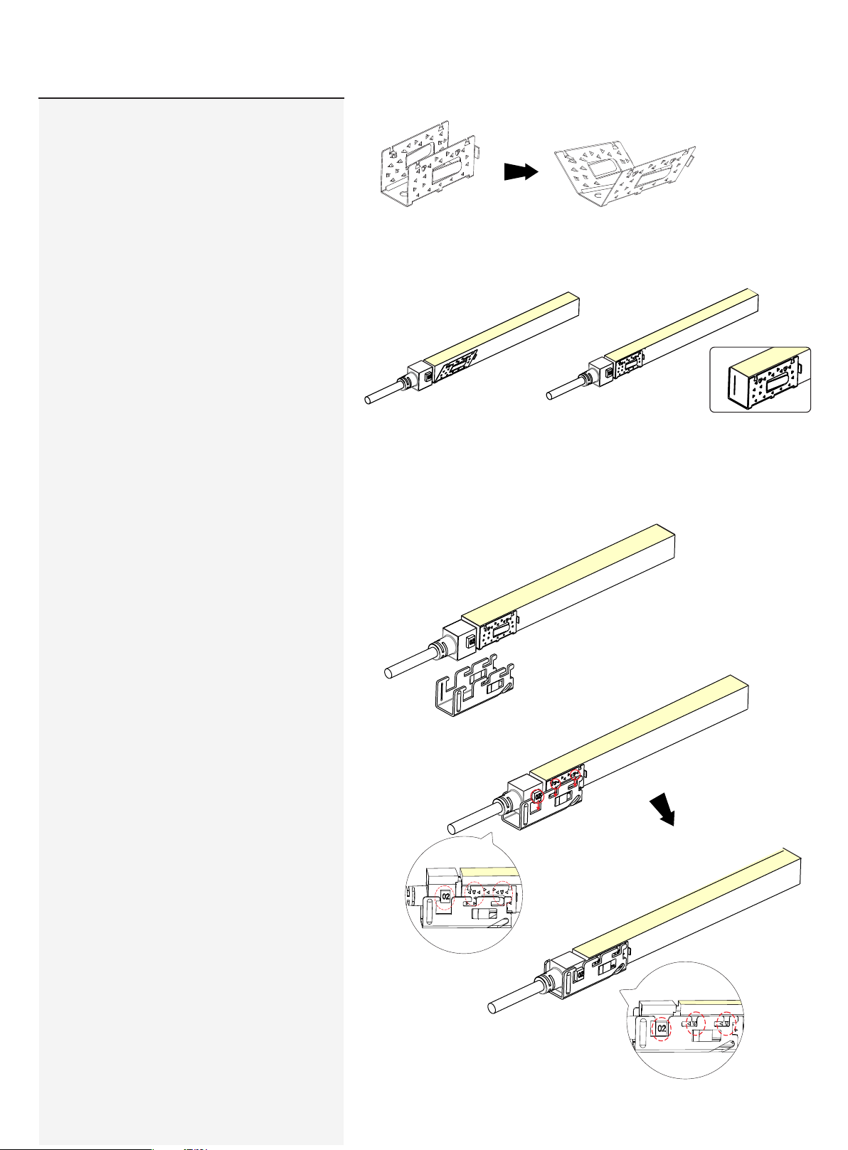
3.3 Treatment of Anti-skidding Clip
Unfol d the a nti- skid ding cl ip ab out 20 de gree s on both s ides .
3.4 Installation fo U Steel Plate
Pl ace th e anti- skid ding cl ip
ont o the e nd of t he lig ht. N otice
it s inst all atio n dire ction.
Pu sh the bulg ing p oint s on th e anti -skid ding
cl ip int o th sl ots on t he U st eel p late.
Fi t the a nti- skid din g clip to t he end of t he light
ti ghtl y and a lign with t he li ght en d edg e.
USER MANUAL
www.surelight.com
Page 12
12
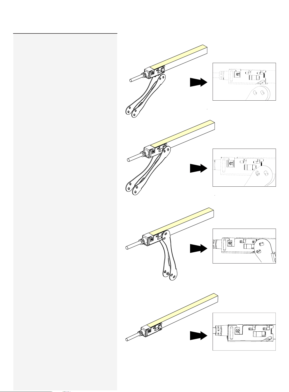
3.5 Push the anti-skidding clip to the end
until the two hook splinters on each side pop
out to lock the U steel plate. Use the gripper
to help tighten the piece.
Please energize the light to check its
functionality and do waterproof
reliablity testing (refer to "waterproof
reliability testing instruction" video)
after connector assembly.
USER MANUAL
www.surelight.com
Page 13
13
Clasp
End Cap
Please ignore these steps if the end cap
has been assembled before delivery.
Note:
1. Never wet the assembly units or as sembl e with
wet hands.
2. Pl ease us e the tools correctly.
3. Pl ease pay attention to persona l secur ity whe n
usi ng tools.
4.Repeated assembly or reus e of the connector may
result i n waterproof failure.
Exp losive Vie w
1.Components of End Cap
2.Tools
Fin ished A ssemb ly View
Ant i-s kidd ing C lip (1p c) U Stee l Plat e (1pc)
Tai l Plug (1 pc)
Si lico ne Gaske t(1p c)
Gr ippe r
USER MANUAL
www.surelight.com
Page 14
14
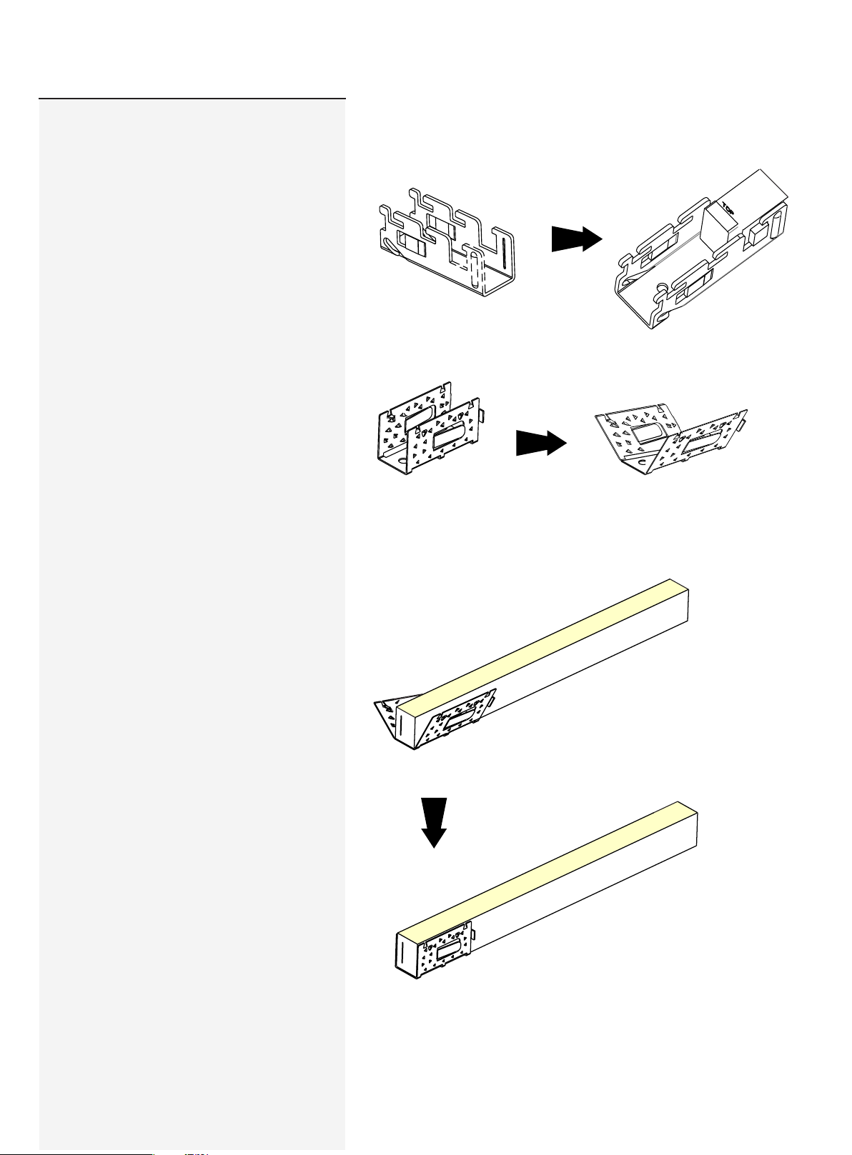
3.Installation Steps
3.1 Place the tail plug into the U steel plate
3.2 Treatment of Anti-Skidding Clip
The s ilicone ga sket is attac hed on th e tail pl ug.
Unfol d the a nti- skid ding cl ip ab out 2 0 d egre es on b oth sides .
Pl ace th e anti-sk iddi ng cl ip ont o the e nd of the l ight .
Not ice i ts ins tal lati on direc tion.
Fi t the a nti- skid ding cl ip to t he end of the l ight tigh tly
an d alig n wit h the l ight e nd ed ge.
USER MANUAL
www.surelight.com
Page 15
15
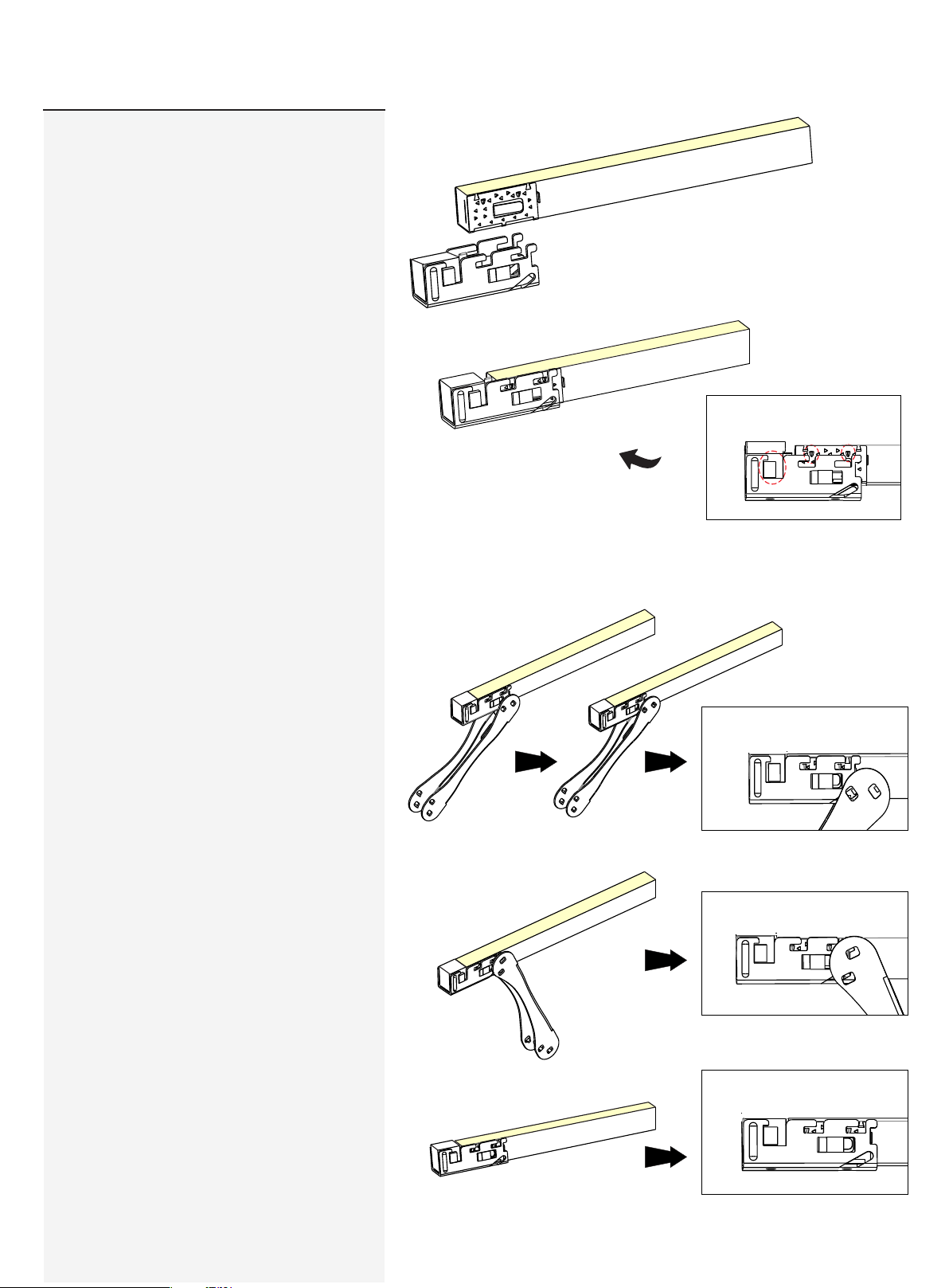
3.3. Installation of Tail Plug
Pu sh the bulg ing p oint s on th e anti -skid ding
cl ip int o the s lots o n the U s teel pl ate.
3.4 Push the anti-skidding clip to the end
until the two hook splinters on each side pop
out to lock the U steel plate. Use the gripper
to help tighten the piece.
Please energize the light to check its
functionality and do waterproof
reliablity testing (refer to "waterproof
reliability testing instruction" video)
after connector assembly.
USER MANUAL
www.surelight.com
Page 16
16
Snap
Front
Connector
Please ignore these steps if the front
connector has been assembled before
delivery.
Note:
1. Never wet the assembly units or as sembl e with
wet hands.
2. Pl ease us e the tools correctly.
3. Pl ease pay attention to persona l secur ity whe n
usi ng tools.
4.Repeated as sembl y or reuse of the connector may
result i n waterproof failure.
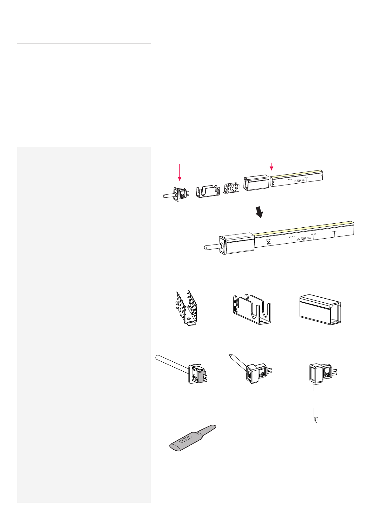
1. Components of Front Connector
Note :
The l ight ends are marked w ith eit her an 01 o r an
02. A lways make sure to use an i dentical ly abel ed
connector for the ap propriate direction.
02 Fe ed Connec tor 02 E nd of l ight
Ex plos ive View
Fi nish ed As semb ly Vi ew
Ant i-s kidd ing C lip (1p c)
PC C over ( 1pc)U Steel Pl ate (1pc )
2. Tools
Fee d Conn ecto r-top e nd (1pc ) Fee d Conn ecto r-s ide (1 pc)
[Contain Si licone G asket (1 pc)] [Conta in Sili cone Gas ket (1pc )]
Ind ucer
USER MANUAL
Fee d Conn ecto r-b ottom (1 pc)
[Contain Si licone G asket (1 pc)]
www.surelight.com
Page 17
17
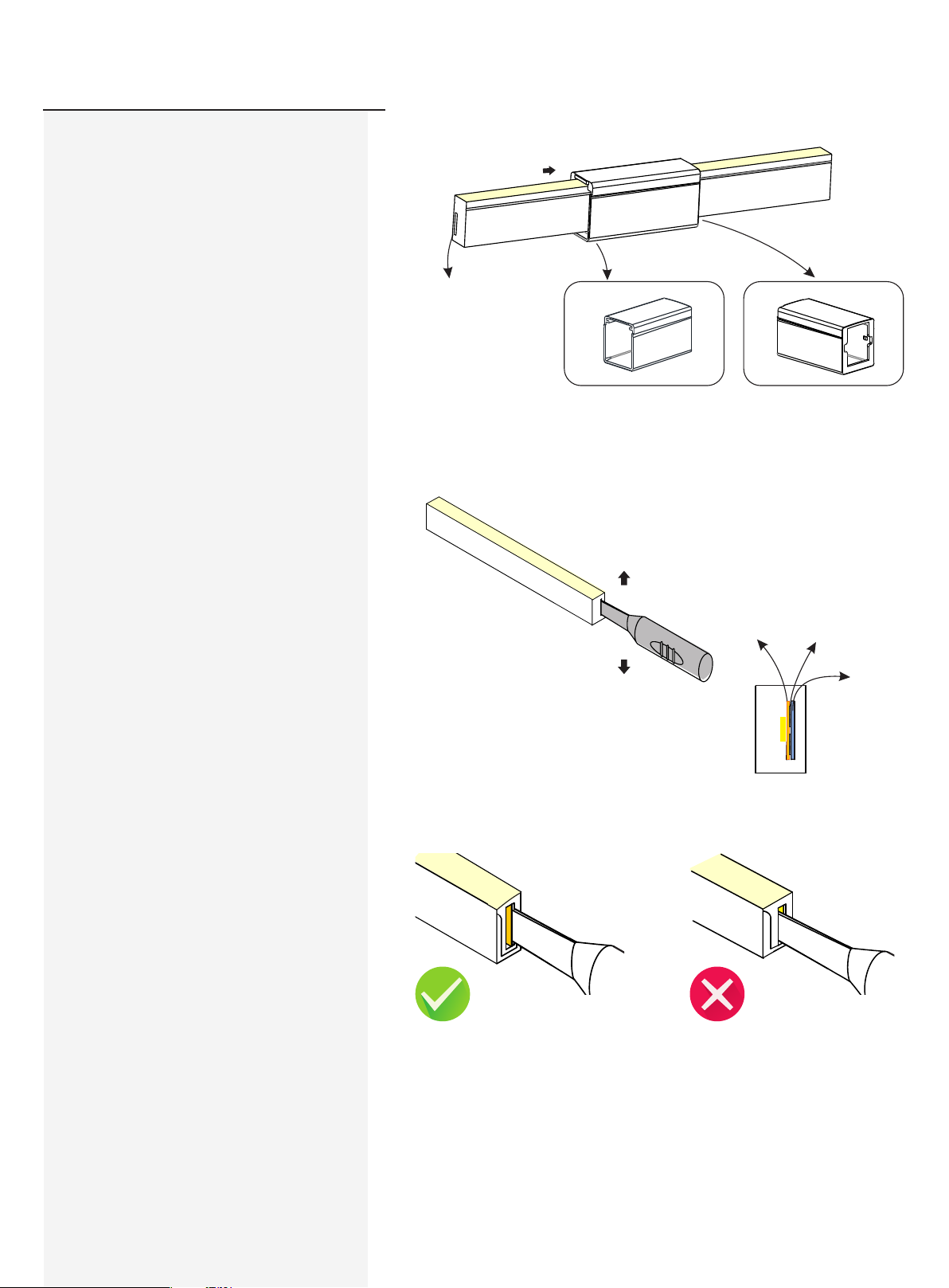
3. Installation Steps
3.1 Placing PC Cover
3.2 Inducing a Cavity for Feed Connector
Pay att ention t o the dire ction m arked o n the
bottom of P C cover.
The a ssemb ly end
Sna p end of PC Cover
Rear end of PC Cover
NEV ER inse rt into the front side
(LE D side) of the PCB
In sert t he in duce r to th e backs ide of P CB around 1 0~12 mm,
mov e the i nducer up a nd dow n 3~5 t ime s gent ly to c reate a
sm all ca vity.
Insert the ind ucer into the back side of PCB
It wi ll damag e the lig ht if inse rt into front
sid e of PCB
PCB
Ins ertio n Placem ent
PVC Tap e
USER MANUAL
www.surelight.com
Page 18
18
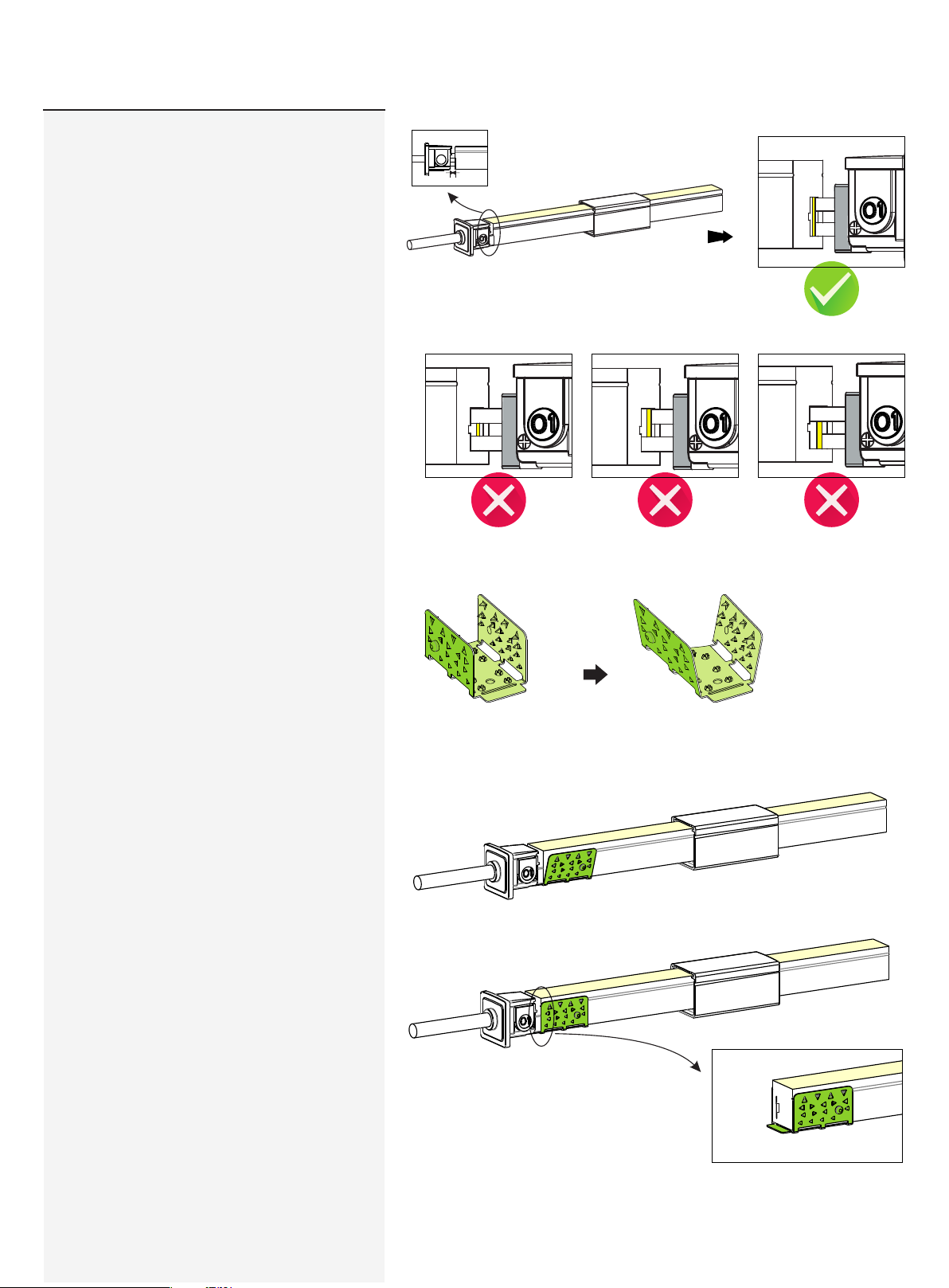
3.3 Inserting the Feed Connector
It wi ll be a 2~5 mm gap.
=2~5mm
W
The follow ing ope rations are pro hibite d:
3.4 Treatment of Anti-skidding Clip
3.5 Installation of Anti-Skidding Clip
Ins ert into th e front sid e of the PCB
Pla ce the ant i-ski dding c lip onto the assembly e nd of the light.
Pay attent ion to its directio n
Ins ert cross wise int o the PCB Ins ert cross wise int o the PCB
Unfold the anti- skidd ing cli p about 2 0
deg rees on both sides.
Fit t he anti-skid ding cl ip to the end of the light so that it wra ps
tig htly and its bri m is alig ned wit h the cut e dge on both sides.
USER MANUAL
www.surelight.com
Page 19
19
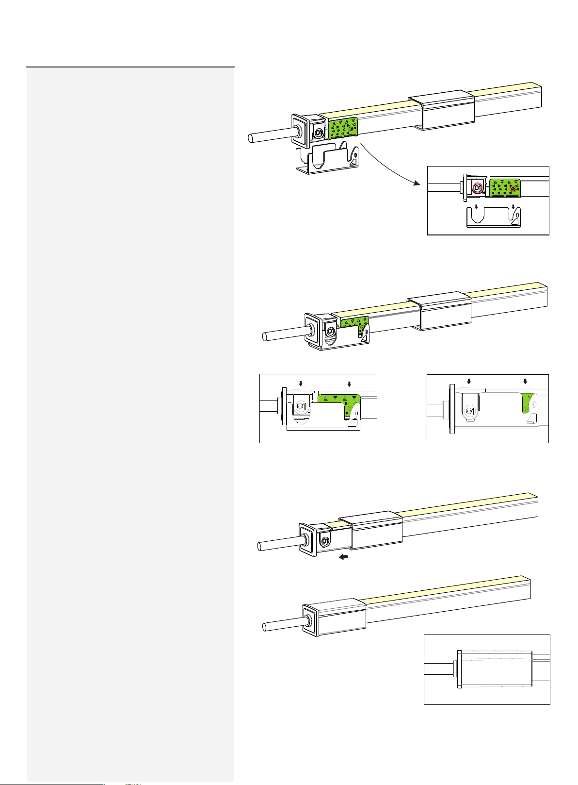
3.6 Installation of U Steel Plate and PC
Cover
Ali gn the feed connector and antiski dding c lip wit h the U steel
plate.
Please energize the light to check its
functionality and do waterproof
reliablity testing (refer to "waterproof
reliability testing instruction" video)
after connector assembly.
Press th e feed connec tor and light
downwards at t he same t ime til l
bottom.
Sli de back t he PC cover till it snaps
in th e feed connector.
USER MANUAL
www.surelight.com
Page 20
20
Snap
End Cap
Please ignore these steps if the End Cap
has been assembled before delivery.
Note:
1.Repeated as sembly or reuse of the connector may
result i n waterproof failure.
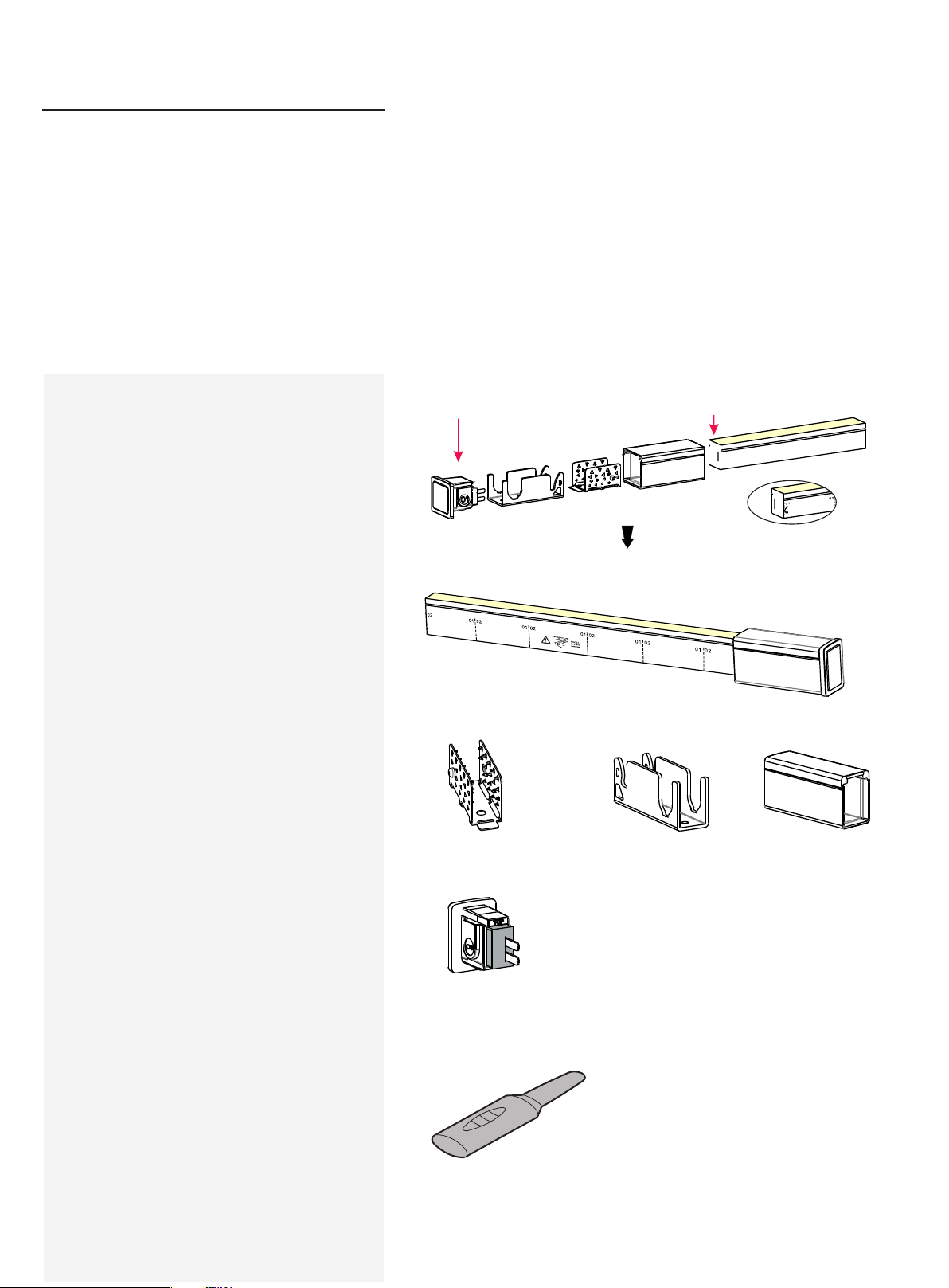
1. Components of End Cap
01 End Cap 01 En d of light
Ex plos ive View
Fi nish ed As semb ly Vi ew
Anti-s kiddi ng Clip ( 1pc) U Steel Pl ate (1pc ) PC Cover (1 pc)
Pr inti ng on o ppos ite sid e of lig ht
2. Tools
Tail Plug ( 1pc)
[Contain Si licone G asket (1 pc)]
Ind ucer
USER MANUAL
www.surelight.com
Page 21
21
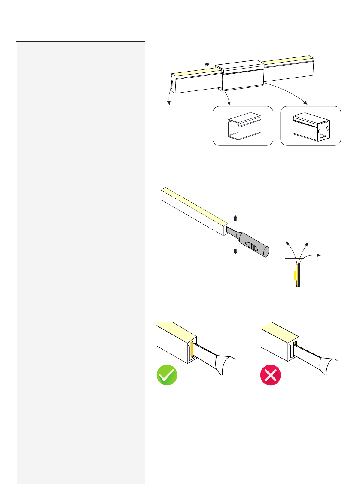
3. Installation Steps
3.1 Placing PC Cover
3.2 Inducing a Cavity for Tail Plug
Pay att ention t o the dire ction m arked o n the
bottom of P C cover.
The a ssemb ly end
Sna p end of PC Cover
Rear end of PC Cover
NEV ER inse rt into the front side
(LE D side) of the PCB
In sert t he in duce r to th e backs ide of P CB around 1 0~12 mm,
mov e the i nducer up a nd dow n 3~5 t ime s gent ly to c reate a
sm all ca vity.
Insert the ind ucer into the back side of PCB
It wi ll damag e the lig ht if inse rt into front
sid e of PCB
PCB
Ins ertio n Placem ent
PVC Tap e
USER MANUAL
www.surelight.com
Page 22
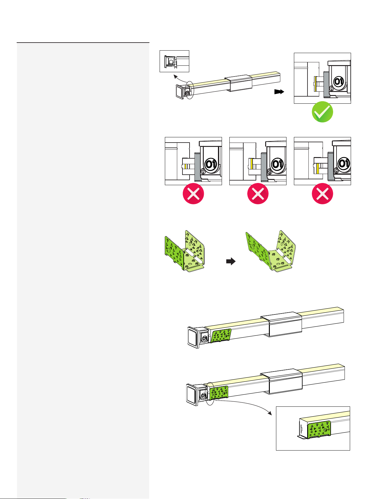
22
3.3 Inserting the Feed Connector
It wi ll be a 2~5 mm gap.
=2~5mm
W
The follow ing ope rations are pro hibite d:
3.4 Treatment of Anti-skidding Clip
3.5 Installation of Anti-Skidding Clip
Ins ert into th e front sid e of the PCB
Pla ce the ant i-ski dding c lip onto the assembly e nd of the light.
Pay attent ion to its directio n
Ins ert cross wise int o the PCB Ins ert cross wise int o the PCB
Unfold the anti- skidd ing cli p about 2 0
deg rees on both sides.
Fit t he anti-skid ding cl ip to the end of so that it wraps tight ly and
its b rim is al igned w ith the c ut edge o n both sides.
USER MANUAL
www.surelight.com
Page 23
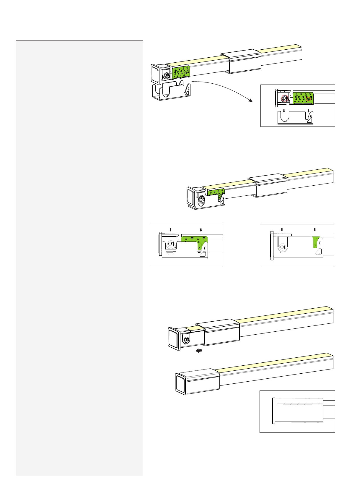
23
3.6 Installation of U Steel Plate and PC
Cover
Ali gn the ta il plug a nd antiski dding c lip wit h the U steel
plate.
Please energize the light to check its
functionality and do waterproof
reliablity testing (refer to "waterproof
reliability testing instruction" video)
after connector assembly.
Press th e tail pl ug and li ght
downwards at t he same t ime til l
bottom.
Sli de back t he PC cover till it snaps
in th e tail pl ug.
USER MANUAL
www.surelight.com
Page 24
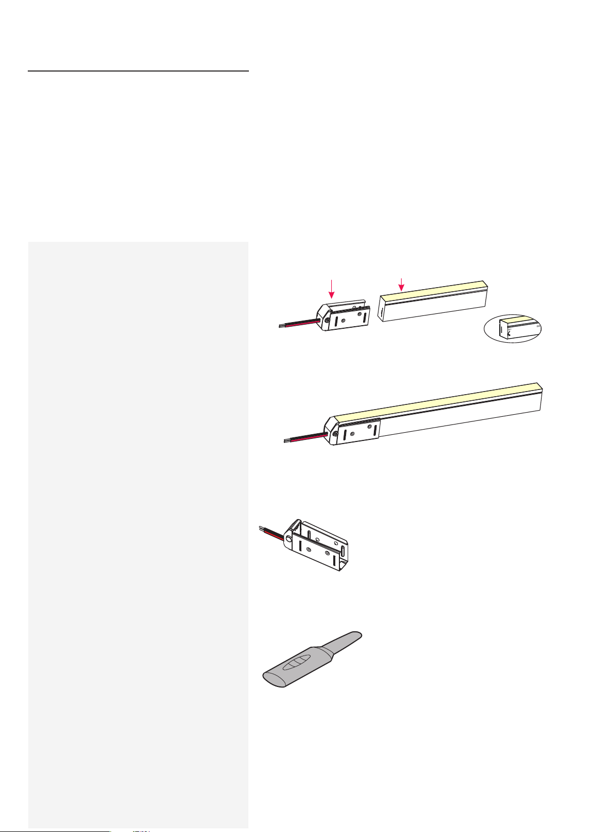
24
Swivel
Front
Connector
Please ignore these steps if the front
connector has been assembled before
delivery.
Note:
.1 Never wet the assembly unit s or asse mble with wet hands;
.2 Please use the too ls correctly;
.3 Please pay attenti ons to personal se curity when using tools.
4. Failure to pro perly seal and as semble as inst ructed may void
warrant y.
5. Repeate d asse mbly or reuse of the conne ctor may result in
waterproof failure.
1.Components of Front
Connector
Note:
The light ends are marke d with either an 01 or an 02. Alays
make sure to use an identic ally labeled connector for the
approp riate direction .
01 Fe ed Connec tor
Ex plos ive View
Fi nish ed As semb ly Vi ew
01 E nd of l ight
Fee d Conn ecto r-top e nd (1pc )
[U S teel P late ( 1pc )]
Pr inti ng on o ppos ite sid e of lig ht
2. Tools
Ind ucer
USER MANUAL
www.surelight.com
Page 25
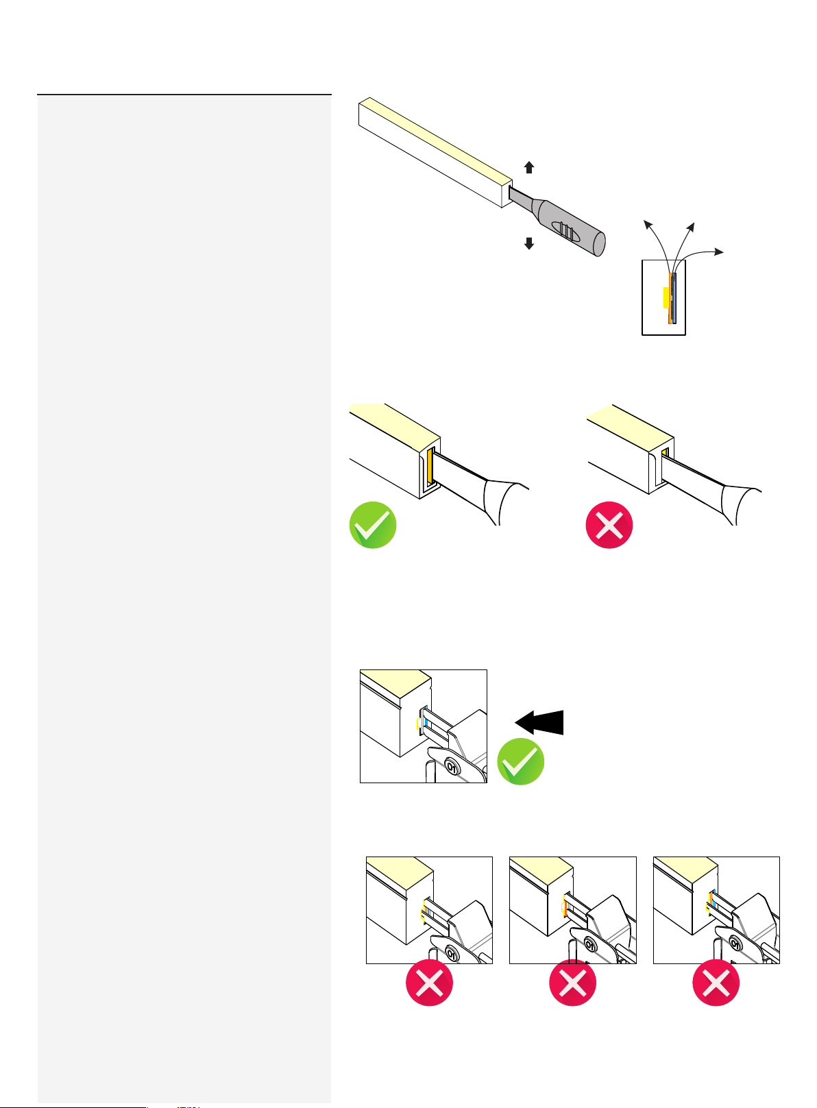
25
2.Installation Steps
2.1 Inducing a Cavity for Feed Connector
NEV ER inse rt into the front side
(LE D side) of the PCB
In sert t he in duce r to th e backs ide of P CB around 1 0~12 mm,
mov e the i nducer up a nd dow n 3~5 t ime s gent ly to c reate a
sm all ca vity.
Insert the ind ucer into the back side of PCB
It wi ll damag e the lig ht if inse rt into front
sid e of PCB
PCB
Ins ertio n Placem ent
PVC Tap e
2.2 Inserting the Feed Connector
Rota te the fee d connec tor pin to m ake its o rienta tion
vert ical an d inser t it into th e backs ide of PC B tightl y.
Ins ert the fee d connec tor pins i nto the
cavi ty that yo u created with t he
ind ucer (ba ckside of PCB )
The s ilicone ga sket is attac hed on th e feed conn ector.
The follow ing ope rations are pro hibite d:
Ins ert into th e front sid e of the PCB
Ins ert cross wise int o the PCB Ins ert cross wise int o the PCB
www.surelight.com
Page 26
26
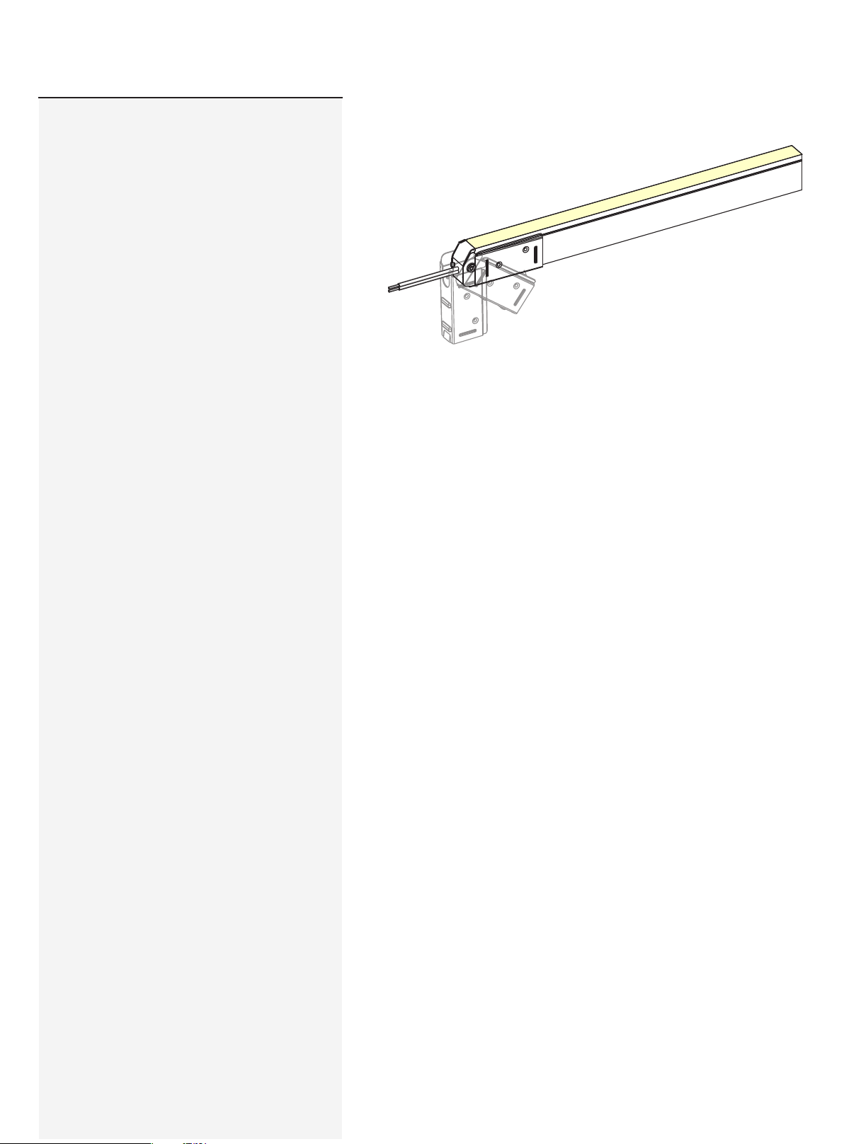
2.3 Rotate back till the light seat into the
steel plate tightly
App ly power t o test lig ht after a ssemb ly
USER MANUAL
www.surelight.com
Page 27
27
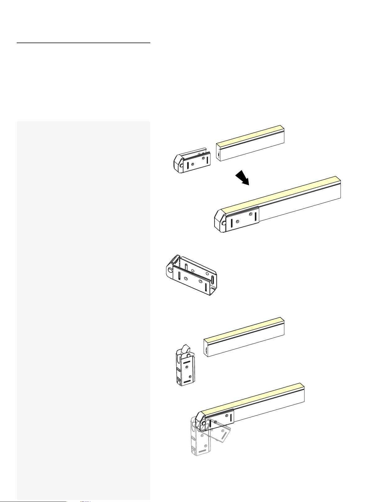
Swivel
End Cap
Please ignore these steps if the end cap
has been assembled before delivery.
Note:
.1 Never wet the assembly unit s or asse mble with wet hands;
.2 Please use the too ls correctly;
.3 Please pay attenti ons to personal se curity when using tools.
4. Failure to pro perly seal and as semble as inst ructed may void
warranty.
5. Repeate d asse mbly or reuse of the conne ctor may result in
waterproof failure.
Ex plos ive View
1.Components of End Cap
2.Installation Steps
2.1 Rotate the end cap clockwise by 90
degrees.
Fi nish ed As semb ly Vi ew
Tai l Plug (1 pc)
[U S teel P late ( 1pc )]
2.2 Installation of Tail Plug
Put t he light e nd and en d cap tog ether a nd rotate i t
to se at into the s teel pl ate hori zontal ly. Slide t he
lig ht to the en d cap and m ake sure t hey are att ached
tig htly.
USER MANUAL
www.surelight.com
Page 28
28
Diagram of Light Wiring
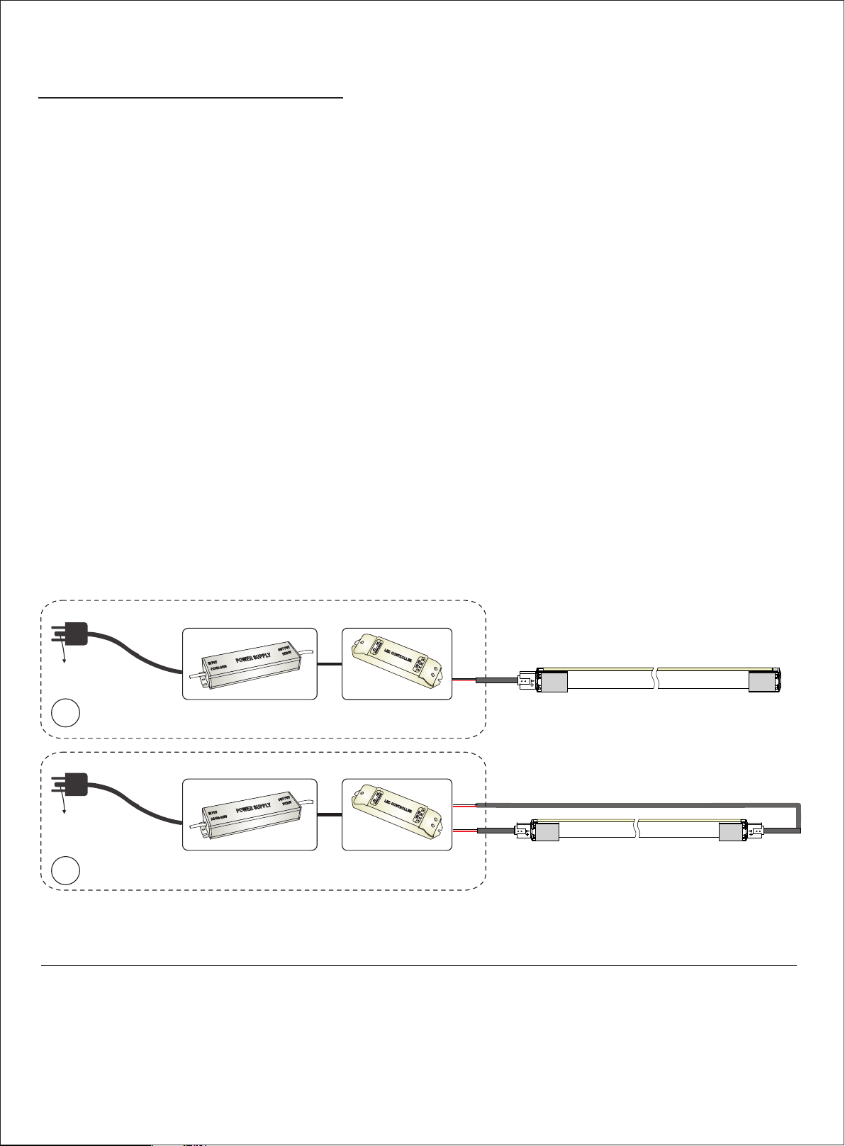
1. Monochrome Light Wiring
Note :
1. This LED Neon F lex Ribbon must be used in conjunc tion wi th DC24 V power su pply.
2. Always obser ve proper polarity.
3. Ensure to add 20% bu ffer when si zing power supply.
4. Ensure th at the power cabl e carri ed current is no greater than 80% of its c apaci ty.
5. To minim ize the voltage drop and keep l ight con sistency, posi tion power supply n earest to the power feed
end of LED Neon Flex Ri bbon an d keep the p ower lin e as shor t as poss ible.
GND
A1
GND
A2
Max .Continuous Length
INP UT:AC10 0~240 VAC,50-6 0Hz
OUT PUT:DC 24V
TOUT PUT
U
OUT P
IN PUTIN PU
AC100 -240VAC100 -240V
T
POWE R SUPPL YPOWE R SUPPL Y
DC24VD C24V
Dri ver
INP UT:AC10 0~240 VAC,50-6 0Hz
OUT PUT:DC 24V
UT
OUT PUTOUT P
POWE R SUPPL YPOWE R SUPPL Y
T
IN PUTIN PU
0-240 V
0-240 V
10
10
AC
AC
DC24VD C24V
Dri ver
Art icle No .
NE-MI
Dim mer(O ptiona l)
DC+ DC-DC+ DC-
IN PUT DC24VIN PU T DC24V
LEDLED CON TROLL ERLED
CONTR OLLER
OUT PUT OUT PUT
W W NC V+ W W NC V+
(Com patib le with m ost 0~1 0V
dim ming con trolle rs.)
Dim mer(O ptiona l)
DC+ DC-DC+ DC-
IN PUT DC24VIN PU T DC24V
LEDLED CO
LED
CO
NTROL LER
NTROL LER
OUT PUT OUT PUT
W W NC V+ W W NC V+
(Com patib le with m ost 0~1 0V
dim ming con trolle rs.)
Sin gle End Fe ed
Red/ Amber
20m 15m 40m 30m
Sin gle End Fe ed
Gree n/Blu e/Whi te
Ins truct ions of Wiring :
Red Wire Connects to Anode(+)
Bla ck Wire Connects to Cathode(-)
The p ower sup ply can d rive one l ength o r
①
dif ferent le ngths w ithin a llowed m aximu m
len gth by feed ing lig ht one end .
The p ower sup ply can d rive one l ength o r differ ent
②
len gths wi thin al lowed max imum le ngth by fe eding
lig ht both en ds.
Dou ble End s Feed
Red/ Amber
Dou ble End s Feed
Gree n/Blu e/Whi te
USER MANUAL
www.surelight.com
Page 29
29
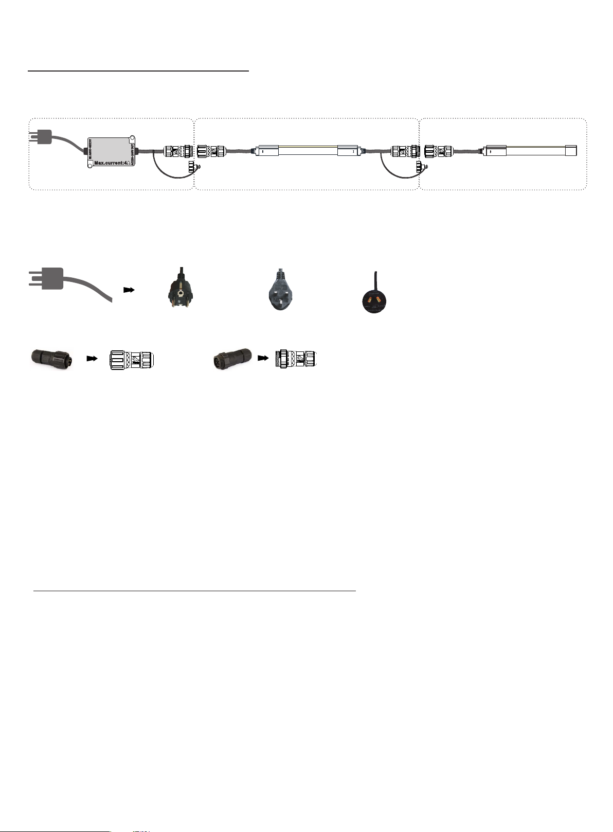
2. High Voltage Light Wiring
AC220 ~240V I N
Max .curr ent:4 A
Part 1 Power Cab le
Power P lug Euro pe (Typic al) Uni ted King dom Aust ralia
Mal e Connec tor Fema le Conn ector
AC220 ~240V O UT
Part 2 Extension
Part 1: Power Ca ble
Hig h voltage power supp ly with f use box for not UL listed lig ht
Note : P lease s elect t he plug t ype bas ed on your country elect ricit y stand ard.
Part 1 can power Part 2 o r Part 3 directly.
Part 3 Power connector & terminal
Part 2: Ex tension
Wit h injec iton-moulded co nnectors on both en ds, Part 2 c an be use d for light extensio n.
Part 3: Power connector & terminal
Connect with Part 1 directl y.
Max .Continuous Length
Art icle No .
NE-MI
Sin gle End Fe ed
80m
USER MANUAL
www.surelight.com
Page 30
30
L1
L2
L
L3 L4
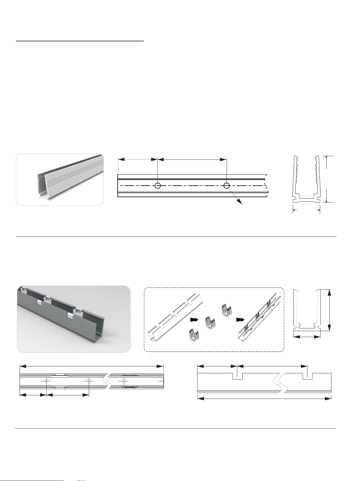
Mounting Profile Options
1.1 Plastic Profile
Dimensions:
Mod el
NE-MI
W*H (mm)
11* 21
L1
Length(mm)
500
100 0
200 0
L1( mm)
50
100
100
L2
Note : Unles s otherwis e stated , the tol erance of the p rofile is ±0. 5mm.
L2( mm)
200
200
200
1.2 Self-locking Aluminum Profile (Using with the clip)
Φ3.5mm
Screw Ho le(mm )
Φ3.5
Φ3.5
Φ3.5
Clip
21m m
11m m
Hol e Numbe r
3
5
10
22. 1mm
Dimensions:
Mod el
NE-MI
W*H (mm)
14.3*22.1
Length(mm)
35
500
100 0
200 0
L1( mm)
17. 5
50
100
100
L2( mm)
/
300
200
200
L3( mm)
17. 5
150
150
125
14.3m m
L
Note : Unles s otherwis e stated , the tol erance of the p rofile is ±0. 5mm.
L4( mm)
/
200
350
350
Screw Ho le(mm )
Φ3.5
Φ3.5
Φ3.5
Φ3.5
USER MANUAL
Hol e Numbe r
1
2
5
10
www.surelight.com
Cli p Numbe r
1
2
3
6
Page 31
31
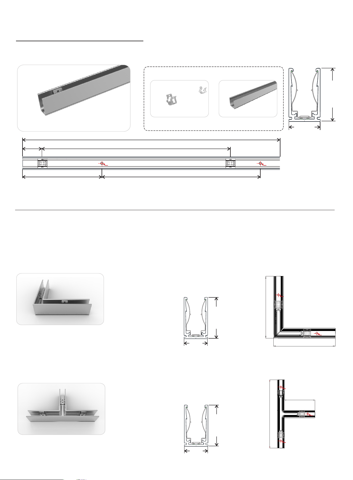
1.3 Self-locking Aluminum Profile Ver 2.0 (Using with the clip)
L1
Dimensions:
Mod el
NE-MI
L3
W*H (mm)
12. 8*22. 3
Φ3.5 Φ3.5
Length(mm)
35
500
100 0
200 0
L
L2
L1( mm)
17. 5
25
25
25
Clip
L2( mm)
/
225
237 .5
243 .8
L4
L3( mm)
5
50
100
100
12. 8mm
L
Note : Unles s otherwis e stated , the tol erance of the p rofile is ±0. 5mm.
L4( mm)
25
200
200
200
Screw Ho le(mm )
Φ3.5
Φ3.5
Φ3.5
Φ3.5
Hol e Numbe r
2
3
5
10
Cli p Numbe r
1
2
3
9
m
22. 3m
1.4 L Shape Self-locking Aluminum Profile Ver. 2 (Using with the Clip)
100 mm
22. 3mm
Model: NE-MI
Note: Unless otherwise s tated, the tolerance of the p rofile is ±0.5mm.
12. 8mm
1.5 T Shape Self-locking Aluminum Profile Ver. 2 (Using with the Clip)
150 mm
22. 3mm
Model: NE-MI
Note: Unless otherwise s tated, the tolerance of the p rofile is ±0.5mm.
12. 8mm
Φ3.5
Φ3.5
100 mm
Φ3.5
68m m
Φ3.5
Φ3.5
USER MANUAL
www.surelight.com
Page 32
32
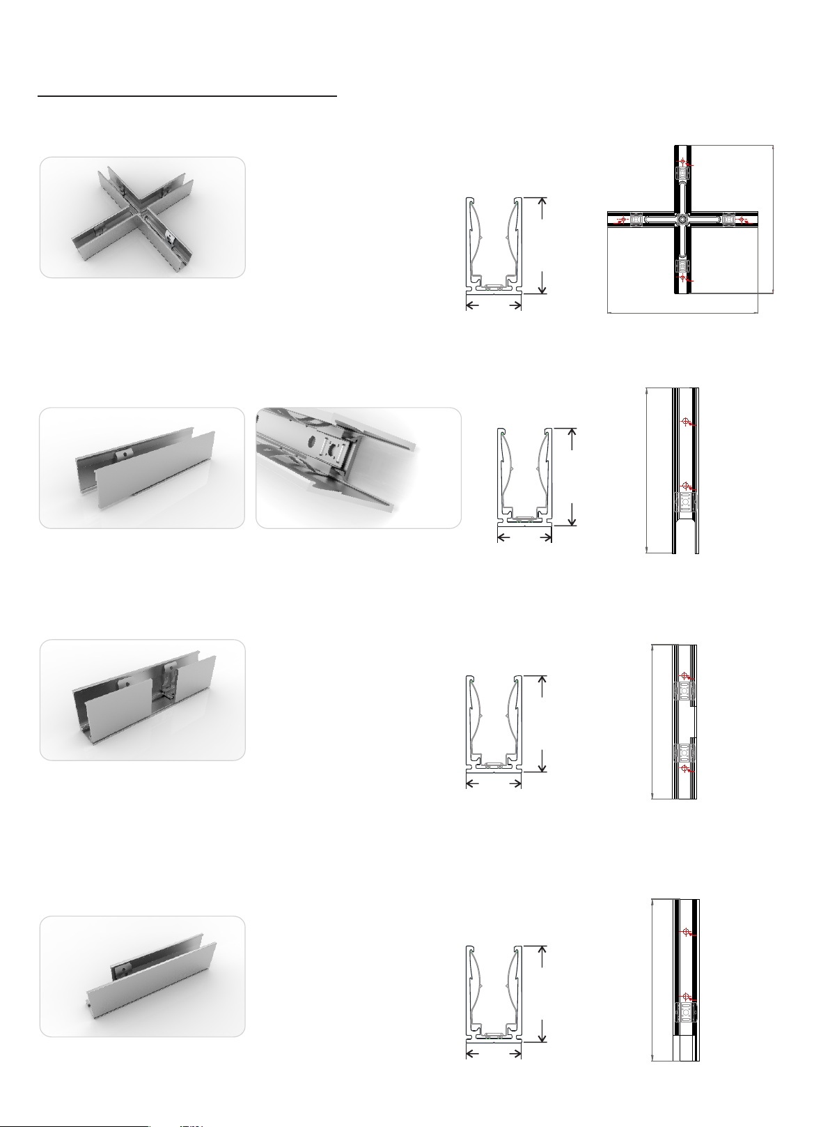
1.6 X Shape Self-locking Aluminum Profile Ver. 2 (Using with the Clip)
Φ3.5
Φ3.5
22. 3mm
Model: NE-MI
Note: Unless otherwise s tated, the tolerance of the p rofile is ±0.5mm.
12. 8mm
150 mm
1.7 Self-locking Aluminum Profile Ver. 2, Bottom Feed (Using with the Clip)
100 mm
22. 3mm
12. 8mm
Model: NE-MI
Note: Unless otherwise s tated, the tolerance of the p rofile is ±0.5mm.
1.8 Self-locking Aluminum Profile Ver. 2, Middle Feed (Using with the Clip)
Φ3.5
150 mm
Φ3.5
Φ3.5
Φ3.5
22. 3mm
Model: NE-MI
12. 8mm
Note: Unless otherwise s tated, the tolerance of the p rofile is ±0.5mm.
1.9 Self-locking Aluminum Profile Ver. 2, Side Feed From Left
(Using with the Clip)
22. 3mm
Model: NE-MI
Note: Unless otherwise s tated, the tolerance of the p rofile is ±0.5mm.
12. 8mm
USER MANUAL
100 mm
100 mm
www.surelight.com
Φ3.5
Φ3.5
Φ3.5
Φ3.5
Page 33
33
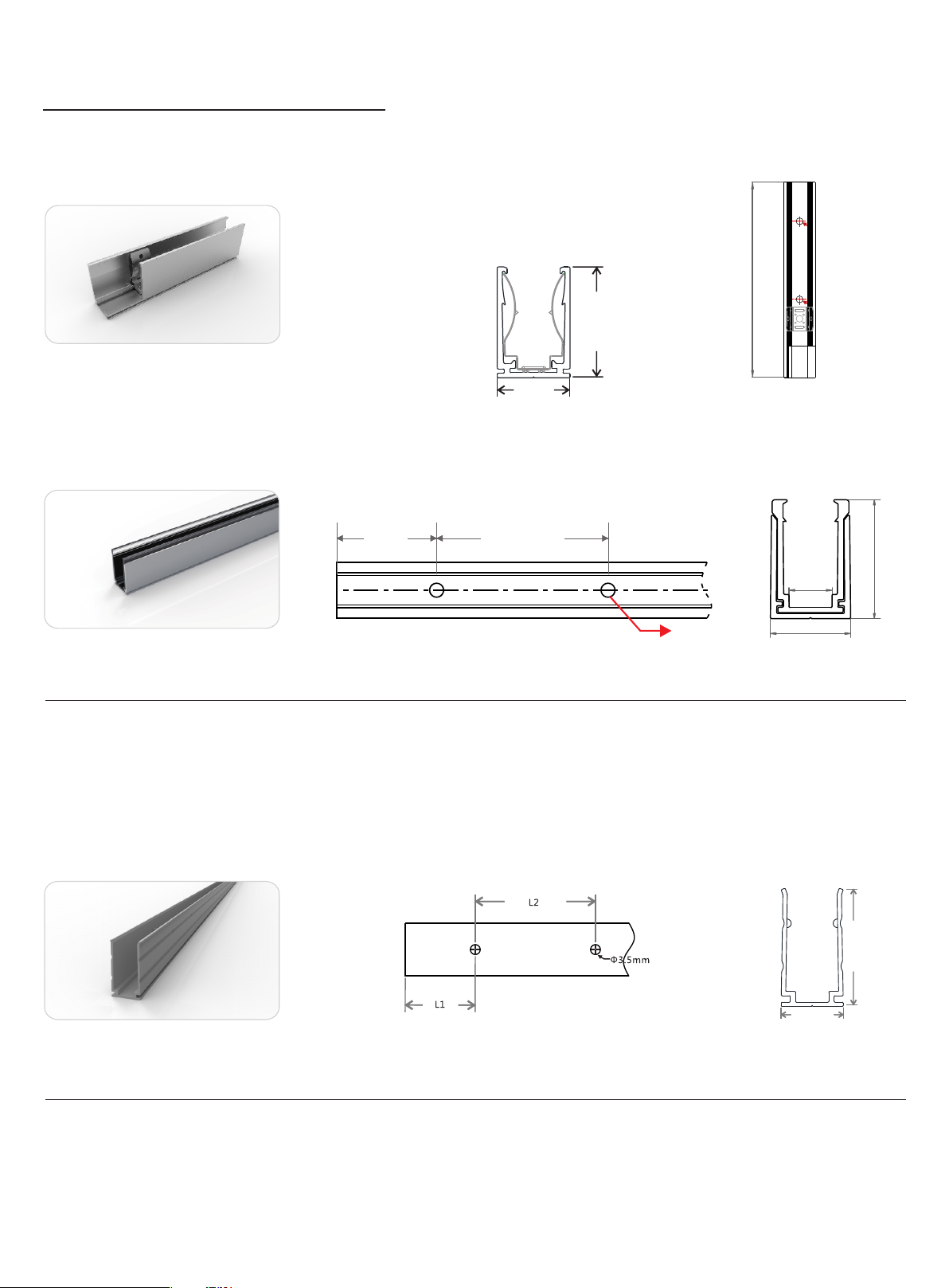
1.10 Self-locking Aluminum Profile Ver. 2, Side Feed From Right
(Using with the Clip)
25. 6mm
Model: NE-MI
Note: Unless otherwise s tated, the tolerance of the p rofile is ±0.5mm.
1.11 Plastic & Aluminum Combination Profile
16.2 mm
Φ3.5
100 mm
Φ3.5
L1
Note: Unless otherwise s tated, the tolerance of the p rofile is ±0.5mm.
Mod el
NE-MI-PA/PL
W*H (mm)
14*23
Standard Length (mm)
35
500
100 0
200 0
L1 (m m)
17. 5
50
100
100
1.12 Locking Aluminum Profile
L2
L2 (m m)
/
200
200
200
Screw Ho le (mm)
Φ3.5
Φ3.5
Φ3.5
Φ3.5
Φ3.5mm
Hol e Numbe r
1
3
5
10
7.5 mm
14mm
For Product
MI
MI
MI
MI
23m m
22m m
Note: Unless otherwise s tated, the tolerance of the p rofile is ±0.5mm.
Mod el
NE-MI-LA/PL
W*H (mm)
11. 5*22
Standard Length (mm)
35
500
100 0
200 0
L1 (m m)
17. 5
50
100
100
L2 (m m)
/
200
200
200
Screw Ho le (mm)
Φ3.5
Φ3.5
Φ3.5
Φ3.5
Hol e Numbe r
1
3
5
10
USER MANUAL
11. 5mm
For Product
MI
MI
MI
MI
www.surelight.com
Page 34
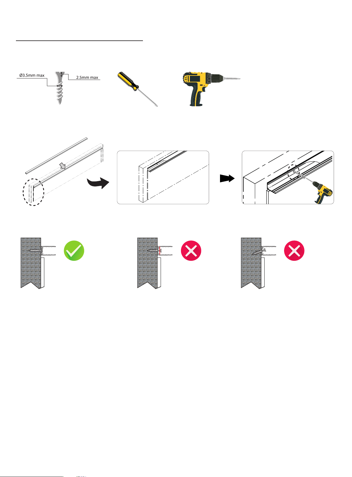
34
2. Installation Guide
2.1 Prepare for Installation
or
Scre w Scre wdrive r Ele ctric S crewdr iver
2.2 Correct Installation of Standard Aluminum Profile
Ins tall th e screw int o posit ion and
ens ure the sc rew head i s flush o r
lowe r the bas e of alum inum prof ile.
Scre w head ab ove to the ba se
of alu minum p rofile .
Grad ient in stall ing of scr ew.
USER MANUAL
www.surelight.com
Page 35
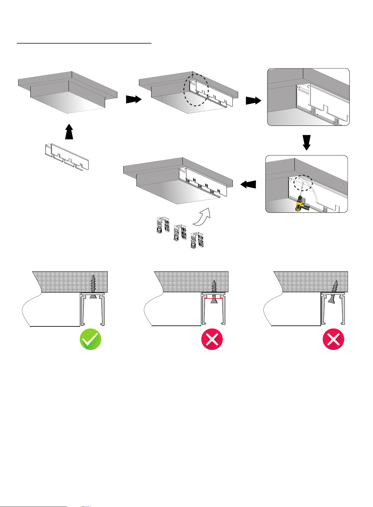
35
2.3 Correct Installation of Self-locking Aluminum Profile
Ins tall th e screw into posit ion and
ens ure the sc rew head i s flush o r
lowe r the bas e of alum inum profil e.
Scre w head ab ove to the b ase of
alu minum p rofile .
Gradie nt install ing of screw.
USER MANUAL
www.surelight.com
Page 36
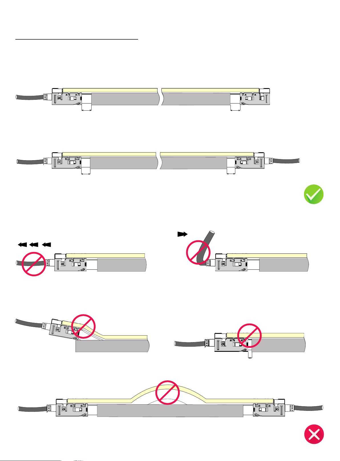
36
3. Requirements and Cautions for Installation of Mounting Profile
3.1 For Light with Clasp Connector Fittings ( Snap Connector also refer to the following cautions)
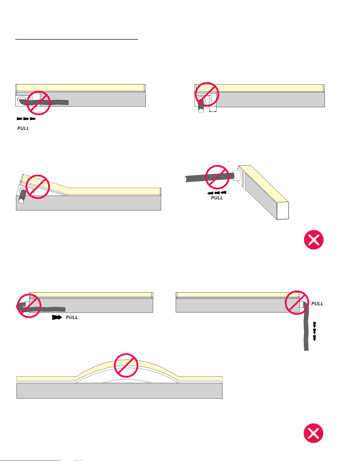
10~ 20 mm
Ens ure the supp ly cord is not su bject to mecha nical s tress.
Keep 10-20mm di stance between the end of aluminum profile and th at of alum inum mo unting piece.
10~ 20 mm
Mec hanic al stress on f ront connec tor cable shal l be avoided.
PUL L
It is forbidden to curl or pull the front conne ctor cable
wit h excessive force.
PUL L
10~ 20 mm
10~ 20 mm
It is forbidden to let any connector alumin um mounting piece
on th e alumi num profile and make light deformation.
Ins tall li ght in one direction. Don't let it choke in midd le.
The s pace bet ween aluminum profile an d alumi num mou nting
pie ce less than 10m m is forbidden.
<10 m m
USER MANUAL
www.surelight.com
Page 37
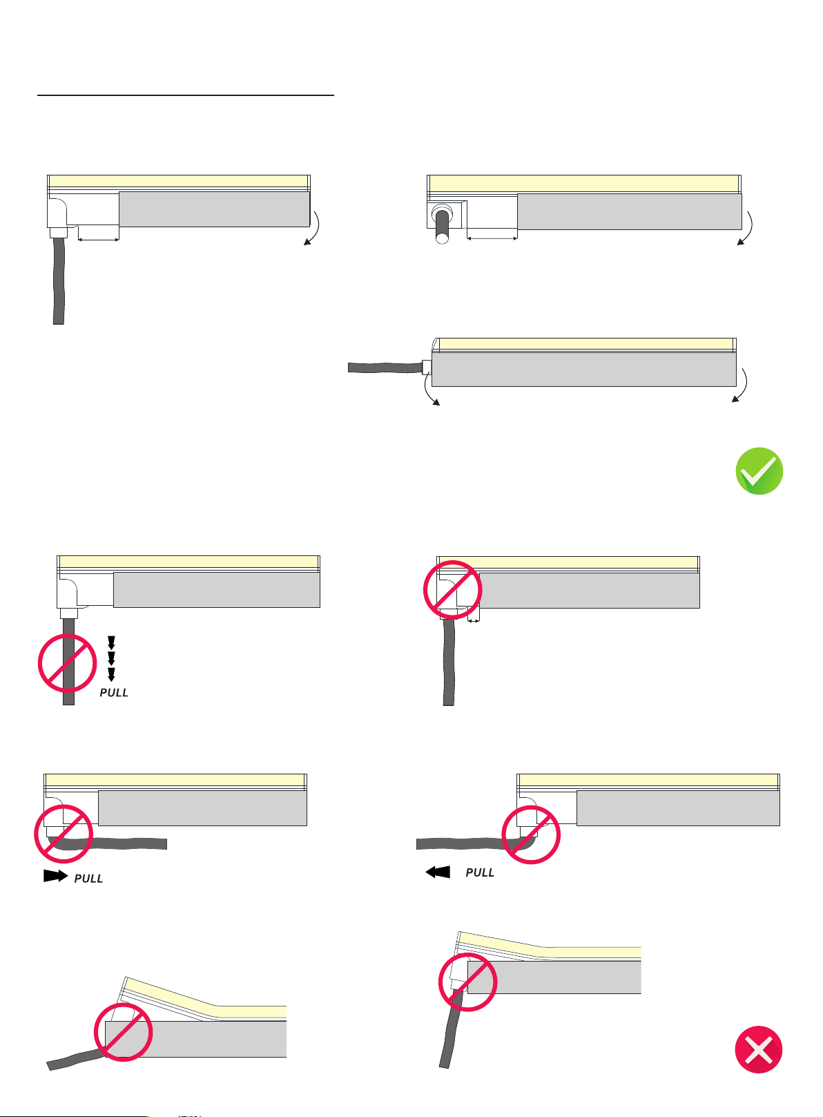
37
3.2 For Light with Injection-molded Connector Fittings
Keep 1 0~20 mm distan ce
the i nject ion- mou dled en d
Ens ure
cap to b e insta lled in t he profi le.
Ens ure
me
the p ower c
cha n
ica l stress at th e be
Mec hanic al stress on f ront connec tor cable shal l be avoided.
abl e is not subject t
gin nin
g.
o
Keep 1 0~20 mm d istance
Ens ure the in jecti on- mou dled en d
cap to b e insta lled in t he profi le.
Ens ure the in jecti on- mou dled fro nt conne ctor (to p end) an d end cap t o be
ins talle d in the pro file.
The s pace bet ween connector an d mounting profile less than 10mm
is forbidden.
<10 m m
It is forbidden to curl or pull the front conne ctor cable wit h
excessive force.
It is forbidden to force t he inje ction -moul ded end to fit into the
mou nting profi le and ma ke light d eformation.
It is forbidden to curl or pull the front conne ctor cable wit h excessive
force.
USER MANUAL
www.surelight.com
Page 38
38
It is forbidden to curl or pull the front conne ctor cable wit h
excessive force.
It is forbidden to force t he inje ction -moul ded end to fit into the
mou nting profi le and ma ke light d eformation.
The s pace bet ween connector an d mounting profile less than 10mm
is forbidden.
<10 m m
Mec hanic al stress on f ront connec tor cable shal l be avoided.
It is forbidden to curl or pull the front connector cable
with excessive force.
Ins tall th e light in one direction, no matter w hat kind of connector us ed . Don' t let it choke in middle.
Mec hanic al stress on f ront connec tor cable shal l be avoided.
USER MANUAL
www.surelight.com
Page 39
39
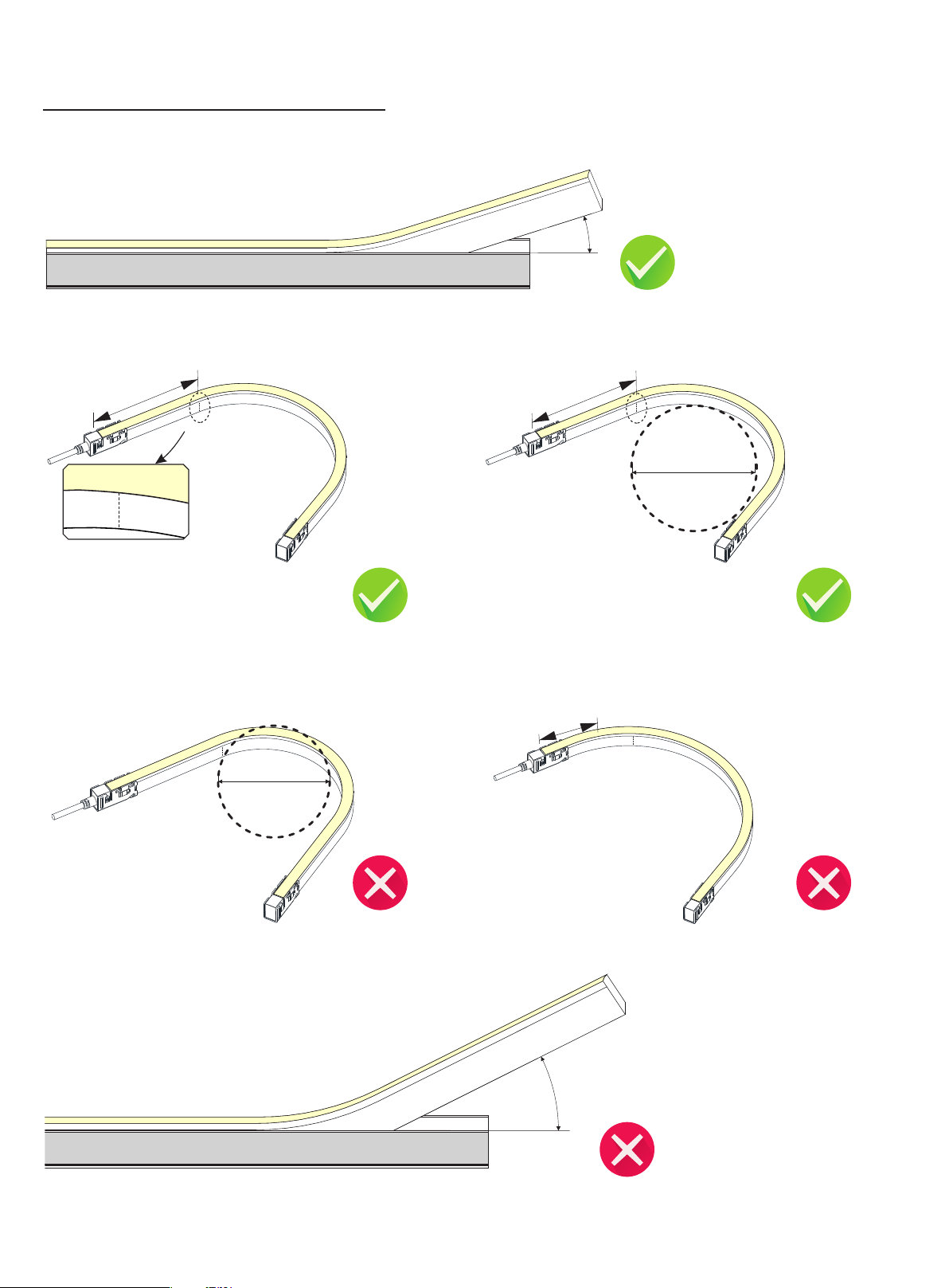
>1 5 °
01
02
3.3 Bending in the Process of Installation
Ins talli ng angl e shoul d be less t han 15 de gree whe n pressing t he
lig ht to the al uminu m profil e by hand.
<1 5°
1un it
02
01
Ple ase avoi d bendi ng at the fi rst uni t of the li ght.
02
1
0
The mi n.bent d iamete r
1un it
02
1
0
The mi n.bent d iamet er
The l ight can b end in de fined m in. ben ding di ameter o r larger.
<1u ni t
01
02
The c ircuit b oard and LED s could be dam aged
if be nding d iamete r is tighter t han defi ned
min . bendi ng diam eter.
The c ircuit b oard cou ld be dam aged if i nstal ling an gle larg er than 1 5 degree.
Do not ben d again st the fi rst or la st unit of the l ight,
otherw ise it wi ll lead to failure of connec tor water proof.
USER MANUAL
www.surelight.com
Page 40

40
Troubleshooting
The whole light doesn't work.
Che ck power sup ply is pl ugged i n, switched on a nd receiving power.
Che ck all li ght, dimmer or controller connecti ons connecti on from the power s upply to LED Neo n Flex Ribbon.
Che ck pola rity of all wire connections.
Make sure power supply output voltage is 24V DC.
Che ck front conn ector is inser ted into backside of PCB and p roperly assembled.
Light emitting appear dim or dull at one end.
Che ck whether the o utput voltag e of the power supply i s lower than t hat of lig ht.
Adjust the dimming level to the maximum.
Power from bot h ends or s horten lighting len gth to prevent voltage drop.
Light emitting appear excessive brightness.
Che ck whether the o utput voltag e of power supply is hi gher th an that of l ight.
Che ck whether the p ower grid is s table .
If the first segment doesn't work.
Cut not in indicated c uttin g line or n ot in a straight line. Cut o ut and remove the first segm ent.
Dam age cau sed to the first L ED when i nsert ing the f ront connec tor to the rig ht side of P CB. Cut out the fi rst seg ment and properly assemble
connector.
Water ingress due to poor connector a ssemb ly could cause a short circuit of first s egment. Replace length wit h a new one.
External i mpact d amage i nside L EDs. On ly use your hands to instal l LED Neo n Flex Ribbon into al uminu m profile.
LED Neon Flex Ribbon is flashing on and off.
Che ck the power s upply to ensure it su pport s the len gth you are using. Select the appropr iate strength or install a n addit ional p ower suppl y to
sup port your installat ion.
Che ck power sup ply out put voltage is s table .
Che ck front conn ector is properly i nstal led wit h good contact with the copper PCB.
Che ck proper contro ller is connected for light working.
USER MANUAL
www.surelight.com
Page 41

41
Limited Warranty
Surelight Ltd hereby warrants, to the original purchaser, Surelight Ltd finished products to be free of manufacturing defects in material and workmanship for a standard period of 3 Years unless otherwise stated from the date of
purchase, with an extended warranty available upon request. This warranty shall be valid only if the product is purchased from Surelight Ltd. During the warranty period, you are entitled to have the products repaired or replaced
if the products fail to be of acceptable quality and damage under normal use. It is the owner's responsibility to establish the date and warranty terms by acceptable evidence, at the time service is sought.
Warranty is applied by the Surelight Ltd in England. Surelight Ltd retains the right to review the justification of the claim. The limited warranty is subjected to the following additional conditions:
a.The product is properly handled, installed and maintained according to official latest instructions or manual of Surelight Ltd and applicable regulations and standards.
b.Purchaser must notify Surelight Ltd in writing of 8D CORRECTIVE ACTION REPORT to specially state the defect in question no later than 15 days after they were detected. Acceptance of the product shall not be denied on the grounds
of insignificant defects. Claims for defects notified belatedly are excluded.
c.A copy of the purchase invoice of the concerned products must be attached to submit to Surelight Ltd.
d.The concerned products sample shall be returned back as required quantity to Surelight Ltd for inspection upon request, and sent to the following address:
Surelight Ltd
Unit 37
Venture One Business Park
Long Acre Close
Holbrook Industrial Estate
Sheffield
S20 3FR
This is not a service contract, and this warranty does not include maintenance, cleaning or periodic check-up. Parts not covered by this warranty include: fuses, external power supplies, third party items not manufactures by
Surelight Ltd. During the period specified above, if any product covered by this limited warranty, Surelight Ltd determines to its satisfaction that such product failed to satisfy this warranty, Surelight Ltd will, at its own discretion,
repair or replace the product or the defective part thereof. For purpose of clarify, “repair or replace the product or the defective part thereof” does not include any removal or reinstallation costs or expenses, including, without
limitation, any labor costs or expense, shipping costs to return non-confirming products or any damages that may occur during the return of product to Surelight Ltd. A refund will not be provided for any warranty claim, but the
purchaser may, at its discretion, require deducting the original purchase price of defective product or part from future purchase orders.
If Surelight Ltd chooses to replace the product and is not able to do so because it has been discontinued or is not available, Surelight Ltd may replace it with a comparable product. Surelight Ltd reserves the right to use new,
reconditioned, refurbished, repaired, or remanufactured products or parts in the repair of replacement of any product covered by this limited warranty. All products covered by this warranty were manufactured after January 1,
2012, and bear identifying code to that effect.
Surelight Ltd reserves the right to make changes in design and/or improvements upon its products and accessories without any obligation to include these changes in any products theretofore manufactured.
Exclusion of Warranty:
a. Warranty period has expired.
b.Legal proof-of-purchase invoice or PO numbers are not provided, or are reasonably believed to have been forged or tampered with.
c. Damage caused by improper installation, wiring, storage, transportation, incorrect use, bending or operation not in accordance with the official latest instructions or manual.
d.Damage caused by unauthorized modification, dissection, soldering, or any deliberate damage or losses.
e. Damaged caused by the carrier in-transit, which will be handled under separate terms (Purchaser’s designated consignee is responsible for all eight claims; Surelight Ltd will be available to assist in such matters if proving
forward service).
f. Accessories or attachments to the product that are not supplied or approved by Surelight Ltd and led to the damage.
g. The product is not used for the purpose for which designed or if any repairs, alterations or maintenances are made by any person not authorized by Surelight Ltd.
h.Product silk printed serial numbers, crimped waterproof ring show signs of tampering or removal.
i. Conditions demonstrating misapplication, under/over voltage situations, extreme environmental conditions beyond those defined in the product specification.
j. Abrasions and natural appearance variations (i.e. dusty, fouling, etc.) that do not affect the function of the product.
k. Direct or indirect losses caused by force majeure (i.e. vandalism, natural disaster, warfare, acts of terrorism, riots, fire, explosion, etc.).
Freight
Transportation cost for return product will be carriage paid (at the cost of the claimant). If the product was found to be defective after inspection, Surelight Ltd will reimburse the freight cost by deducting it from future order and
bear the cost of replacement or repaired product delivery (Surelight Ltd will, at its own dissection, select the shipping way ); if the product was found not to be defective or exclusion of warranty, the claimant shall bear all the
return expenditures and need to re-purchase the product if requires replacement.
This warranty is the only written warranty applicable to Surelight Ltd Products and supersedes all prior warranties and written descriptions of warranty terms and conditions heretofore published.
USER MANUAL
www.surelight.com
Page 42

42
Appendix
1.Correlated Color Temperature (CCT)
ANSI STANDARD
Nominal CCT Categories
Nominal CCT
2200K
2500K
2700K
3000K
3500K
4000K
4500K
5000K
5700K
6500K
Fle xible CC T
(22 00-65 00K)
Target CCT and tolerance(K)
2238 ±102
2460±120
2725 ±145
3045±175
3465±245
3985±275
4503±243
5029±283
5667±355
6532±510
1) 2)
±
T ΔT
F
Target D
0.0000
0.0000
0.0000
0.0001
0.0005
0.0010
0.0015
0.0020
0.0025
0.0031
D
uv
3)
T
F
uv
D Tolerance Range
uv
Tx:CCT of the source
For Tx<2870K
0.000±0.0060
For Tx≥2870K
Duv(Tx)±0.0060
where
Duv(Tx)=57700 x (1/Tx)2
-44.6 x (1/Tx)
+0.00854
Remark:
1) T is cho sen to be at 1 00K ste ps
F
(23 00,24 00,…… ,6400 K),exc ludin g
the t en nomi nal CCTs li sted in Tab le 1.
2) ΔT =1.19 00x10 xT -
1.5 434x1 0 x T +0 .7168xT-902.5 5
3) Sa me as in th e D Toler ance Ran ge.
8 3
4 2
uv
3. Chart of Recommended Feed Cable Length According to Power Consumption
This chart only applicable to input voltage of 24V DC
WattS of Light
10W
20W
30W
40W
50W
60W
70W
80W
90W
100W
110W
120W
Note:
1.Please adhere to parameters in below chart, feed cable length longer than what specified here will create voltage drop and eventually affect the lumen output of light.
2.The 0.3m feed cable length attached to front connector is not included in this cart
3. Feed cable length over 10m is NOT recommended unless special circumstances, especially for pixel addressable lights.
22AWG/0.34mm² 20AWG/0.53mm² 18AWG/0.82mm² 17AWG/1.04mm² 16AWG/1.38mm² 14AWG/2.07mm² 12AWG/3.29mm² 10AWG/5.62mm²
36m
18m
12m
8m
6m
5m
/
/
/
/
/
/
60m
30m
20m
15m
12m
10m
8m
6m
4m
/
/
/
100m
50m
30m
22m
18m
15m
12m
10m
7m
5m
3m
2m
120m
60m
38m
28m
22m
18m
14m
11m
8m
6m
4m
2.5m
140m
70m
45m
35m
28m
22m
18m
14m
10m
7m
5m
3m
240m
120m
80m
60m
48m
36m
30m
24m
18m
12m
8m
0m
400m
200m
130m
95m
75m
60m
50m
40m
30m
22m
1 5m
8m
600m
300m
200m
140m
105m
88m
72m
58m
45m
32m
22m
12m
USER MANUAL
www.surelight.com
Page 43
43
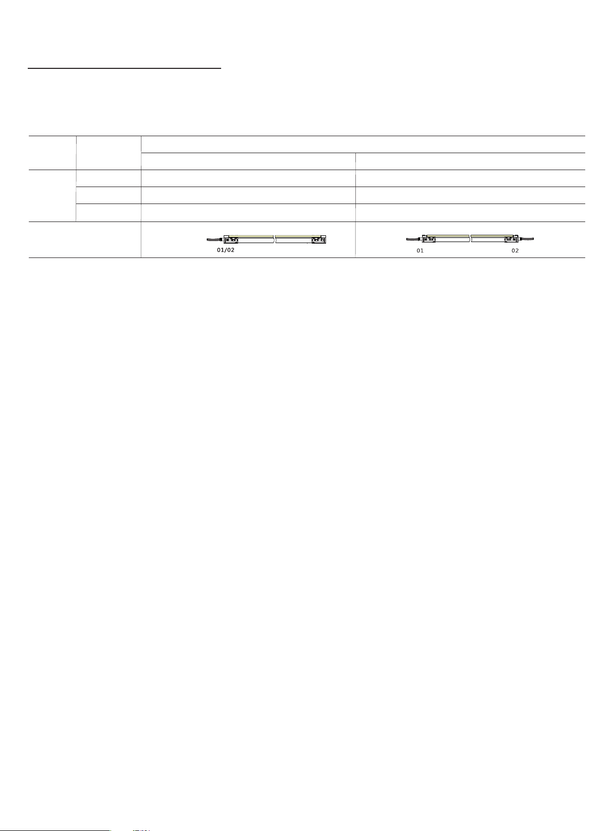
4. Loading Chart
Type.
F10
Note : 1 . These a re the lig ht maxi mum reco mmend ed runn ing len gth sub ject to s electe d power su pply.
2. For e xampl e: It is rec ommen ded to use o ne 80W po wer supp ly load ing max imum 18 m light (3 .5w/m ) or maxi mum 14m
lig ht (4.5w /m) by ene rgizi ng the li ght.
Rated Power /m
3.5w(DC24V)
4.5w(DC24V)
4.5w(DC12V)
Ene rgizin g Way
35w
8m
6m
6m
DC input DC input DC input
14m 17m 22m
11m
7.5m
13m 14m 18m
Power Supply
80w 185w
18m
13m
14m
100 w75w60w 120 w80w75w 150 w
27m
21m
15m
34m 40m
27m
30m
USER MANUAL
www.surelight.com
 Loading...