

Page 1
SURE HEAT
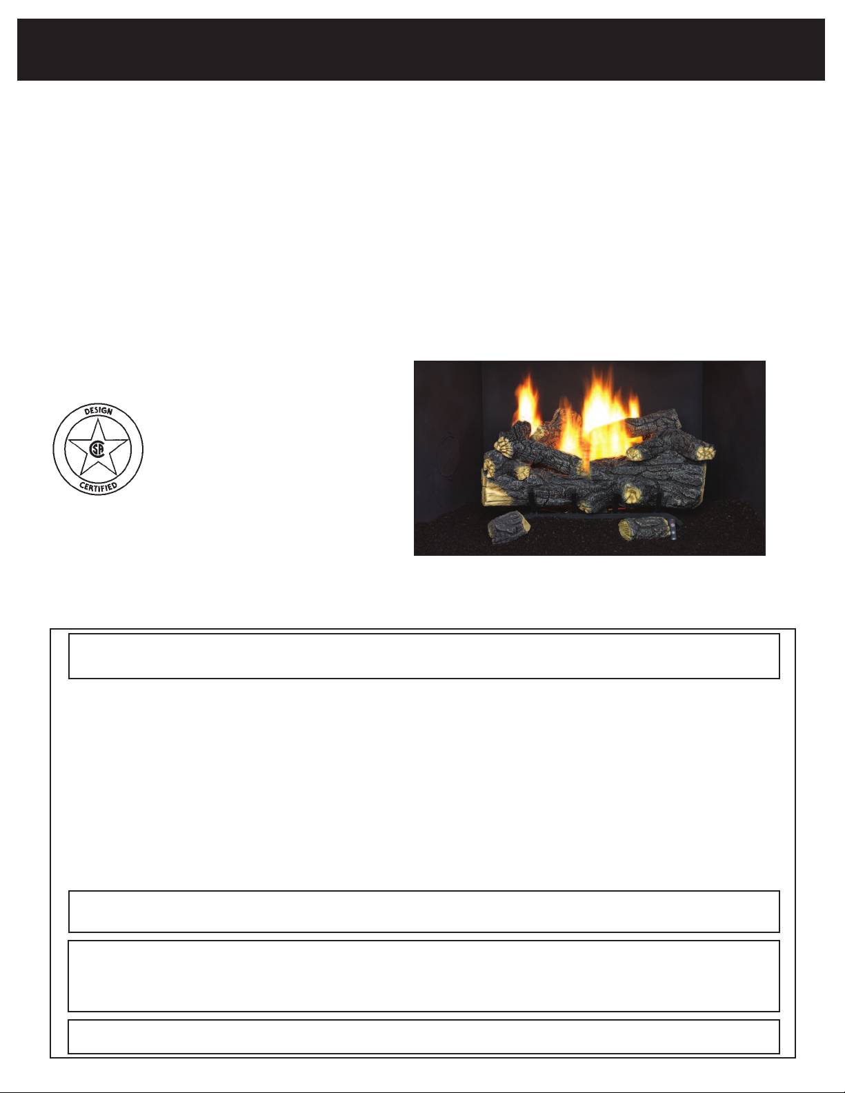
Installation and Operating Instructions for
NATURAL & L.P. GAS VENT FREE SYSTEM
Model: SCVFMR18, SCVFMR 24/21,
SCVFMR30 (LP or NG Versions)
DANGER:
FAILURE TO FOLLOW THESE INSTRUCTIONS CAREFULLY AND WITHOUT ERROR, OR
FAILURE TO HEED ANY AND ALL WARNINGS IN THESE INSTRUCTIONS CAN RESULT IN
AN EXPLOSION, FIRE OR THE PRODUCTION OF CARBON MONOXIDE GAS WHICH CAN
CAUSE PROPERTY DAMAGE, BODILY INJURY OR DEATH.
Sure Heat
Manufacturing
3130 Moon Station Road
Kennesaw, Ga 30144
Tel: (770) 422-8008
Fax: (770) 424-3842
NOTE: THIS UNIT CANNOT BE CONVERTED TO DIFFERENT GAS TYPES.
WARNING: If the information in this manual is not followed exactly, a fire or explosion may
result causing property damage, personal injury or loss of life.
- Do not store or use gasoline or other flammable vapors or liquids in the vicinity of this or any other appliance.
- WHAT TO DO IF YOU SMELL GAS:
• Do not try to light any appliance.
• Do not touch any electrical switch.
• Do not use any telephone in your building.
• Immediately call y
• Follow the gas suppliers instructions.
ou cannot reach your gas supplier, call the fire department.
• If y
- Installation and ser
our gas supplier from a neighbor’s telephone.
vice m
ust be perf
ormed by a qualified installer, service agency or the gas supplier.
This is an unvented gas-fired heater. It uses air (oxygen) from the room in which it is
installed. Provisions for adequate combustion and ventilation air must be provided.
THIS APPLIANCE MAY BE INSTALLED IN AN AFTER MARKET MANUFACTURED (MOBILE) HOME, WHERE NOT
PROHIBITED BY STATE OR LOCAL CODES. INSTALL ONLY IN A SOLID-FUEL BURNING FIREPLACE OR
APPROVED VENTLESS FIREBOX ENCLOSURE (MANUFACTURED UNVENTED FIREPLACE) AS SPECIFIED BY
THESE INSTRUCTIONS.
*AFTER MARKET
: COMPLETION OF SALE, NOT FOR PURPOSE OF RESALE, FROM THE MANUFACTURER.
THIS APPLIANCE IS ONL
THE APPLIANCE. THIS APPLIANCE IS NOT CONVERTIBLE FOR USE WITH OTHER GASES.
Y FOR USE
WITH
1
TYPE OF GAS INDICA
THE
TED ON
THE RA
TING LABEL A
ACHED TO
TT
Page 2

This appliance is designed as an unvented room heater when installed in a non-combustible fireplace with the flue damper
closed.
his appliance may be used as a heating appliance only if unvented heating appliances are permitted by local state and city
T
codes. If unvented heaters are not permitted, then the fireplace vent damper must be locked at the minimum area required
by local codes, or in the absence of local codes, by the latest edition of the National Fuel Gas Code (ANSI Z223.1 or latest
edition).
his installation manual contains valuable safety instructions and installation procedures that should be understood before
T
installation of the unit. The owner of this appliance should keep this instruction manual to refer to in the future. It is the
installer’s responsibility to instruct the owner of this unit in the proper use and maintenance of this appliance.
DANGER: THIS APPLIANCE, AS ANY GAS-FIRED APPLIANCE, CAN PRODUCE POISONOUS CARBON MONOXIDE,
ALONG WITH OTHER COMBUSTION PRODUCTS. CARBON MONOXIDE, IN STRONG CONCENTRATIONS, CAN
CAUSE SICKNESS, SERIOUS PERSONAL INJURY OR DEATH.
GASEOUS FUELS ARE HIGHLY EXPLOSIVE IN CERTAIN CONCENTRATIONS AND ARE VERY FLAMMABLE. ANY
GAS LEAKS IN THE PLUMBING SUPPLYING GAS TO THIS APPLIANCE CAN LEAD TO FIRE OR EXPLOSION.
WHEN PROPERLY INSTALLED, USED AND MAINTAINED, THIS APPLIANCE SHOULD NOT PRODUCE CARBON
MONOXIDE IN DANGEROUS QUANTITIES. HOWEVER, SINCE CARBON MONOXIDE CAN BE DEADLY POISONOUS,
THE INSTALLER AND ALL USERS OF THIS APPLIANCE SHOULD READ AND FOLLOW THESE INSTRUCTIONS
CAREFULLY.
IMPORTANT INFORMATION
Fireplace sizing guide and BTU information: BTU Information
Set
e Height Width Width Depth Max. Min. Max. Min.
Siz
18” 18” 22” 18” 12” 34,000 22,000 34,000 22,000
24”/21” 18” 28” 23” 15” 39,000 22,000 39,000 22,000
30” 18” 34” 25” 15” 39,000 22,000 39,000 22,000
Sufficient space must be provided around this appliance to provide air for combustion and ventilation. Any alterations
to this unit or its controls may be hazardous.
Do not install this heater in bedrooms or bathrooms.
These instructions should be studied carefully before the installation and operation of this unit.
The installation must conform with local codes, or in the absence of local codes, with the National Fuel Gas Code ANSI Z223.1, 1992,
or latest edition.
The installation and repair of this unit should be conducted by a licensed or qualified service person.
WARNING: This appliance is only for installation in a solid fuel burning fireplace made of non-combustible
materials or approved ventless firebox enclosure.
This appliance must be kept clear from combustible materials, gasoline or other flammable vapors and liquids.
Solid fuels should not be bur
Opening Front Rear Fireplace Natural Gas L.P. Gas
ented room heater is installed.
ned in a fireplace where an un
v
Keep burner and control compartment clean. See installation and operating instructions accompanying heater.
Due to high temperatures, the appliance should be located out of traffic and away from furniture and draperies.
Children should be supervised when they are in the same room as the appliance.
ns or clothing ignition.
ur
oid b
All people should be notified of high surf
This system should be inspected upon installation and ann
keep controls, burner and air passageways clear of any debris.
Do not place any combustible material on or around the appliance.
ace temper
atures of the system to a
ually by a professional service person. It is necessary to
v
2
Page 3

o not use this appliance if any part has been submerged under water. Immediately call a qualified service technician to
D
nspect the appliance and replace any part of the control system and any gas control which has been under water.
i
This heater shall not be installed in a confined space unless provisions are provided for adequate combustion and ventilation.
The National Fuel Gas Code defines a confined space as a a space whose volume is less than 50 cubic feet per 1,000
BTU per hour (4.8m
pace whose volume is not less than 50 cubic feet per 1,000 BTU per hour (4.8m
s
f all appliances installed in that space. Rooms communicating directly with the space in which the appliances are
o
installed, through openings not furnished with doors, are considered a part of the unconfined space.
WARNING: If the area in which the heater may be operated is smaller than that defined as an unconfined space, provide
adequate combustion and ventilation air by one of the methods described in the National Fuel Gas Code, ANSI Z223.1,
1992, Section 5.3.
This appliance is equipped with an ODS (oxygen depletion sensor) pilot light safety system that turns off the appliance if
there is not enough fresh air available. Additional ventilation is obtained by opening a door to another room or opening a
window.
ays ensure that there is proper ventilation from the area the system is operating in.
Alw
Any outside air ducts and/or ash dumps in the fireplace shall be permanently closed at time of appliance installation.
This appliance must be used with glass doors in the OPEN position.
A fireplace screen with an opening for combustion air must be in place when the appliance is operating, unless other
provisions for combustion air are provided.
3
per kw) of the aggregate input rating of all appliances installed in that space and an unconfined
3
er kw) of the aggregate input rating
p
IMPORTANT: During the manufacturing process, this appliance is treated with certain coloring agents. These agents are
not harmful, but may produce annoying smoke and smell as they are burned off. This is a temporary occurrence that
ceases after 10 hours of use. During the “burning off” period, provide ventilation by opening windows, door and the chimney flue to allow odors to dissipate. Any remaining odors will burn off with continued use.
WARNING:This appliance cannot be converted to a gas other than the type for which it was made at the factory.
Operation of this appliance on gasses for which it is not equipped may be hazardous. See identification plate for
gas type designation.
UNPACKING
Unpack the appliance carefully and inspect for missing parts or damages that may have occurred during shipping. If any
part of the appliance is missing or damaged, please notify Sure Heat Manufacturing at (770) 422-8008. An incomplete
or damaged appliance may be hazardous. DO NOT INSTALL A DAMAGED OR INCOMPLETE APPLIANCE.
FIREPLACE PREPARATION
The fireplace needs to be properly prepared before installing this fireplace unit.
1. Turn off gas supply to the fireplace.
2. Clean chimney and fireplace floor of any combustible material to limit the smell from the system.
WARNING: Before installing in a solid fuel burning fireplace, the chimney flue and firebox must be cleaned for soot, creosote, ashes and loose paint by a qualified chimney cleaner.
UNIT PLACEMENT
Place the entire burner system in the center of the fireplace to allow proper air flow on all sides of the unit.
GAS PIPING AND GAS PRESSURE REQUIREMENTS
Check the type of gas that is supplied to your fireplace. Use only the gas type indicated on the heater’s rating plate. If the
gas listed on the plate is not your type of gas supply, DO NOT INSTALL THE SYSTEM. Contact your dealer for the proper
model.
3
Page 4
ll gas piping must be installed to comply with local and national fuel gas codes. Do not use flexible hose unless it is
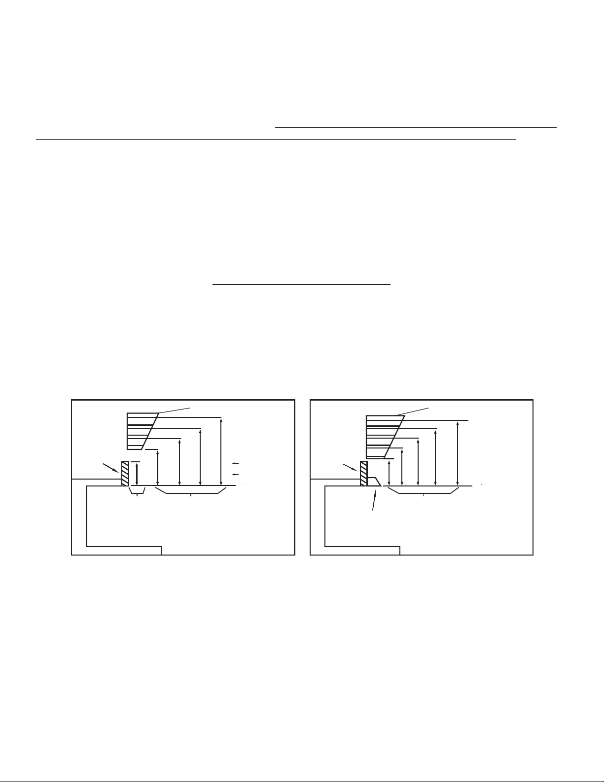
Minimum Mantel Clearance with CanopyMinimum Mantel Clearance
1
0”
8”
6”
2 1/2”
12”8”20”
14”
24”
17”
27”
18”
24”/21“ & 30” MODEL
18” MODEL
30”
20”
MANTEL
M
INIMUM
NON-COMBUSTIBLE
MATERIAL
MINIMUM
NON-COMBUSTIBLE
MATERIAL HEIGHT
DISTANCES TO
UNDERSIDE
OF MANTEL
TOP OF
FIREPLACE
OPENING
UNDERSIDE
OF
M
ANTEL
12”
10”
8”
6”
2 1/2”
8”
MIN.
12”
15”
18”
20”
M
ANTEL
M
INIMUM
NON-COMBUSTIBLE
MATERIAL
CANOPY
DISTANCES TO
UNDERSIDE
OF MANTEL
TOP OF
FIREPLACE
OPENING
UNDERSIDE
OF
MANTEL
(CLEARANCES
FOR ALL
LOG SETS)
A
allowed by local codes. Compounds used on threaded joints of gas piping must be resistant to the action of LP gas.
The gas supply line to the fireplace should not be less than 1/2” inside dimension.
The gas supply must be of sufficient size to provide a minimum natural gas pressure of 7 inches water column for natural
gas or 11 inches for LP gas. The maximum inlet pressure to the appliance must not exceed 10 inches water column
for Natural Gas or 13 inches water column for LP gas. If this appliance is to be supplied with LP gas
, the tank or bottle
supplying the gas must have a regulator that reduces gas pressure between 11 and 13 inches water column.
Include a manual shut-off valve and union in the line so the appliance may be disconnected for servicing. Provide a 1/8”
NPT plugged tapping for pressure gauge connection between the shut-off valve and the appliance. Test for leaks using
soap and water solution after completing the connection. DO NOT USE OPEN FLAME!
WARNING: The appliance and its individual shut-off valve must be disconnected from the gas supply piping
system during any pressure testing of that system at test pressures in excess of 1/2 PSIG (3.5kPa). The appliance
must be isolated from the gas supply piping system by closing its individual manual shut-off valve during any
pressure testing of the gas supply piping system at test pressures equal to or less than 1/2 PSIG. Pressures in
excess of 1/2 PSIG will cause damage to the unit.
FIREPLACE CLEARANCES
To guarantee safe installation into a non-combustible fireplace, certain space requirements must be fulfilled.
1. The clearance from the side of the unit to any combustible wall should not be less than 15 1/2 inches.
2. The clearance from the ceiling to the top of the fireplace opening should not be less than 42 inches.
3. The minimum clearance to combustible items in front of the heater is 36 inches.
4. For any fireplace in which this unit is installed, there are certain mantel clearance requirements that must be met.
ou must have non-combustible material(s) above the fireplace opening. Non-combustible materials (such as slate, marble,
Y
tile, etc.) must be at least 1/2 inch thick. Some decorative fireplace surrounds (cultured marble) may get discolored from
the heat produced by the system. With sheet metal, you must have non-combustible material behind it. If non-combustible material is less than 8”, you must install fireplace canopy (Model AMG-100)
4
Page 5
BURNER ASSEMBLY INSTALLATION
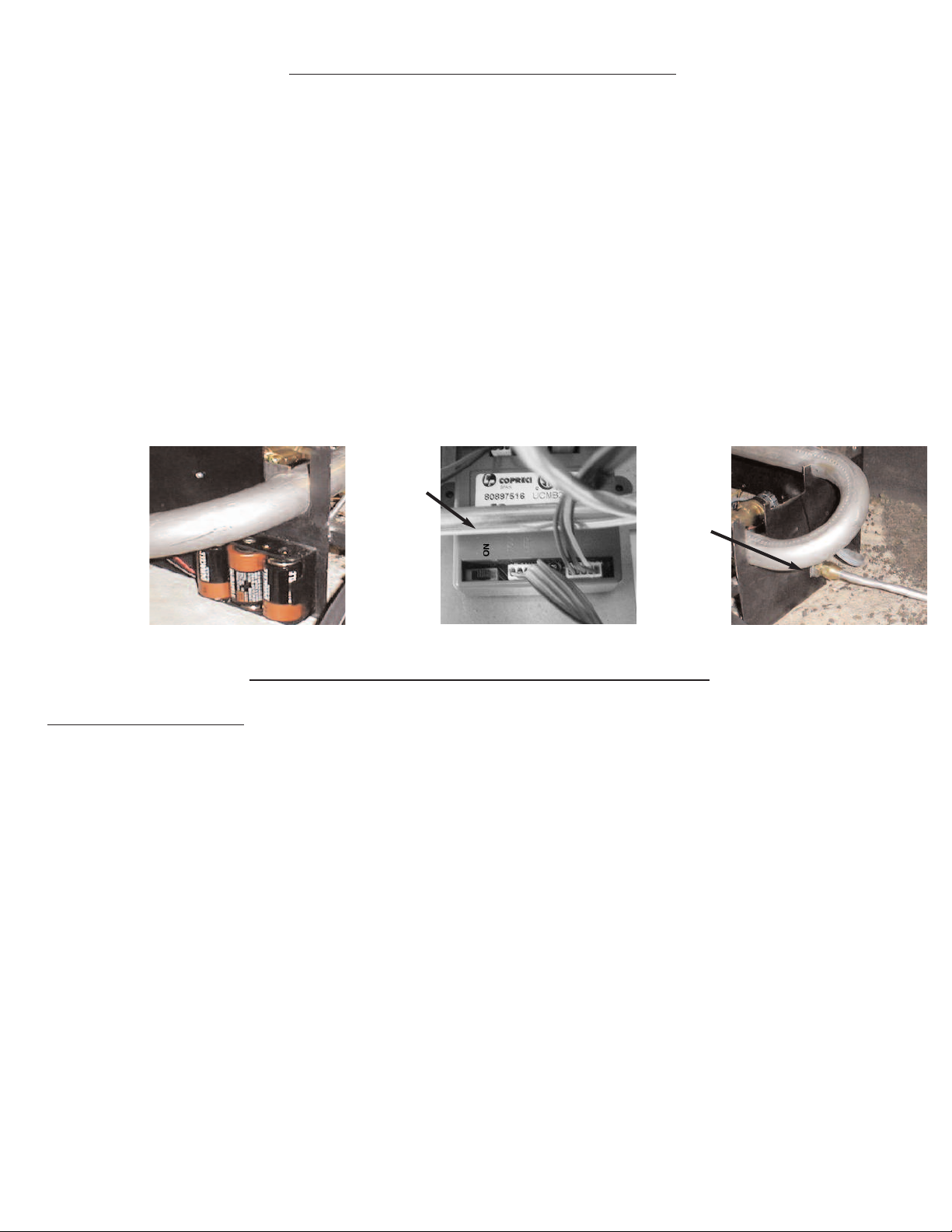
. Install the 3 C Cell batteries. (See Fig. 1)
1
2. Locate the switch on the bottom of the control box (see page 13 for control box location) and verify that it is in the “on”
position. (See Fig. 2)
. Remove the black iron pipe cap from your gas supply pipe.
3
NOTE: Hold the gas supply pipe securely with a wrench to prevent it from rotating loose and unthreading from the
inner wall connection.
4. Tighten the 1/2” NPT by the 3/8” flare supply fitting on the 1/2” gas supply line using pipe joint compound.
5. Place the burner assembly in the center of your fireplace.
6. Fasten the aluminum tube from the gas supply to the gas inlet at the side of the heater assembly. (See Fig. 3)
NOTE: The use of a flexible hose to attach the gas supply to the burn assembly may cause the burner to make
excessive noise.
Burner
requires 3
C batteries.
Located on
left side of
burner.
Fig. 1 Fig. 2 Fig. 3
Switch on
Control
Box in
the “ON”
position.
Gas Line
Hookup
on right
side of
burner
FINAL CHECKPOINTS BEFORE OPERATION
PILOT OPERATION
1. Before setting the logs in place, turn the gas on and check each joint in the the gas line with soap and water solution for
leaks. Bubbles indicate a leak. Repair any leaks and recheck before proceeding.
DANGER: DO NOT USE OPEN FLAME TO TEST FOR LEAKS!
2. We suggest you do a test lighting of the burner assembly before you begin log placement. Be sure to review all safety
precautions in the owner's manual before you light your set.
3. Press the on/off button to bleed the pilot system, after a few seconds you will hear a clicking noise as the pilot lights.
If the pilot does not light, wait 30 seconds and press the on/off button, you will hear a click, then press again to light the
4.
pilot, continue repeating this process until the pilot system lights.
5. It may take several attempts and up to 5 minutes to light the pilot the first time since there will be air in the gas line.
6. Once the pilot flame is lit, wait 15 seconds
7. Then, press the “up”
8. The flame should ignite on the burner bar.
9. Now, press the down control button, the burner should go out and the pilot should remain lit. You are ready for log placement.
control b
utton.
5
Page 6

LOG PLACEMENT
1. The smallest of the 3 large logs is placed on the back tier of the grate. (See Fig. 4 or 7)
2. The second largest log (log with burner notch) is to be placed on the second tier of the grate. (See Fig. 4 or 7)
. The largest log is placed in the front part of the grate with the notches facing upwards. (See Fig. 4 or 7)
3
OTE: The Front log should be as far forward as possible.
N
4. Place the top logs as shown in Fig. 5-6 for 18” sets or Fig. 8-9 for 21”/24” and 30” sets. (Incorrect log placement can
lead to the production of harmful carbon monoxide while the unit is in operation.) Be sure that the logs are correctly
placed in the notches provided for them. There should be no direct impingement of flames on any of the logs.
WARNING: Failure to position the parts specifically approved with this heater may result in property damage or
personal injury
Models: SCVFMR18, SCVFMR24/21, SCVFMR30
18”
Fig. 4
Fig. 5
21”/24”/30”
Fig. 7
DECORATIVE ST
e stone from the bag pro
The decor
placed on or near the burner. Contact with the burner can cause the production of carbon monoxide.
ativ
vided should be spread on the bottom tr
Fig. 8 Fig. 9
ONE
y of the gr
a
ate. The stone should not be
Fig. 6
6
Page 7

FOR YOUR SAFETY READ BEFORE LIGHTING
WARNING: If you do not follow these instructions exactly, a fire or explosion may result, causing property
amage, personal injury or loss of life.
d
A. This appliance is equipped with an electronic ignition device controlled by push-buttons located on the front
of the burner or by a remote control handset.
ouch
T
Buttons
OR Remote Handset
B. BEFORE LIGHTING the unit, smell around the appliance area for gas. Be sure to smell next to the floor
because some gas is heavier than air and will settle on the floor.
WHAT TO DO IF YOU SMELL GAS:
• Do not try to light any appliance
• Do not touch an
y electrical switch
• Do not use any telephone in your building
• Immediately call your gas supplier from a neighbors telephone
• Follow the gas supplier’s instructions
• If you cannot reach your gas supplier, call the fire department
• Installation and service must be performed by a qualified installer, service agency or the gas supplier
C. Use only your hand to push the touch button controls. Never use tools. If the touch buttons will not operate,
do not try to repair. Call a qualified service technician.
WARNING:THE USE OF FORCE OR ATTEMPTED REPAIR MAY RESULT IN A FIRE OR EXPLOSION
D. Do not use this appliance if any part has been under water. Immediately call a qualified service technician to
inspect the appliance and replace any part of the control system and any gas control that has been under
water.
7
Page 8

LIGHTING INSTRUCTIONS FOR REMOTE CONTROLLED SYSTEM
Model SCVFMR
Lighting Set from Burner System
top!!Read the safety instructions on the previous page
1.S
efore proceeding.
b
2. Press the on/off button to bleed the pilot system, after a
few seconds you will hear a clicking noise as the pilot
lights. (See Fig. 10)
3. If the pilot does not light, wait 30 seconds and press the
on/off button, you will hear a click, then press again to
light the pilot, continue repeating this process until the
pilot system lights.
4. It may take several attempts and up to 5 minutes to light
the pilot the first time since there will be air in the gas
line.
5. Wait fifteen (15) seconds after pilot is lit before adjusting
the flame height.
6. To increase the flame height push the up arrow on the
touch pad, until desired flame height is reached. (See
Fig. 11)
Note: Burner has 4 different settings:
1. Pilot
2. Low flame
3. Medium flame
4. High flame
o decrease flame height, push the down arrow on
7. T
the touch pad, until desired flame height is reached.
(See Fig. 12)
Fig. 10
On/Off
Button
Fig. 11
Up
Arrow
Fig. 12
Down
Arrow
8. To turn the burner off, press the down arrow button.
(See Fig.
9. If you wish to turn off the pilot light, push the on/off button.
(See Fig.
12)
10)
8
Page 9

LIGHTING INSTRUCTIONS FOR REMOTE CONTROLLED SYSTEM
Model SCVFMR
Lighting Set from Remote Handset
top!!Read the safety information on page 7 before
1.S
proceeding.
Note: Before the remote control can operate
correctly it must learn the security code
from the control box on the burner.
Note: Make sure the sensor switch on the control box
is in the “on” position. (See Fig. 2 on page 5)
2. For the remote to learn the security code, point the
remote at the burner and press the following buttons:
(See Fig. 13)
On/Off button once - “ON” should start blinking
On/Off+Up+Down (all together) - hold for 1 second
(while “ON” is still blinking)
Set button (while “ON” is still blinking)
A small clock appears while the hand held unit is learning
the code(See Fig. 13)
Remote will return to the “off” position
Set
Manual
On
Fig 13
Clock
Room Temperature
Up button
On/Off button
Down button
Fig 14
One flame is pilot
mode
MANUAL MODE
3. To light the pilot press the following buttons: (See Fig. 14)
On/Off button (“ON” will start blinking)
Set button (while “ON” is still blinking)
This turns the unit on in manual mode - hand should
appear. (See Fig. 14)
o adjust the flame height in man
4. T
(See Fig. 15)
utton
Up b
flame height one setting.
Or
wn button
Do
the flame height one setting.
Note: Bur
5. To turn the pilot off
ner has 4 different settings:
1. Pilot
2. Low flame
3. Medium flame
4. High flame
Press on/off b
Set button (while “OFF” is still blinking)
- Each press r
- Each press lo
utton
ual mode press:
aises the
(“OFF”
will star
wers
linking)
t b
Set
On/Off button
Fig 15
Four flames is high
Up button
Down button
9
Page 10

LIGHTING INSTRUCTIONS FOR REMOTE CONTROLLED SYSTEM
Model SCVFMR
AUTO-THERMOSTATIC MODE
6. To switch to Auto mode press the following buttons:
(See Fig. 16)
uto
Set button - “AUTO” will start blinking
Set button (while “AUTO” is still blinking)
Note: After switching to Auto mode, the temperature
will start blinking. This is the temperature you
wish the room to reach.
7. To change the temperature in Auto mode press the following
buttons: (See Fig. 17)
Up button -Temperature will start blinking
(each press raises the temperature one degree)
Set button (while temperature is still blinking)
Or
Down button -Temperature will start blinking
(each press lowers the temperature one degree)
Set button (while temperature is still blinking)
The number of flames automatically adjusts to the correct
setting in order to reach the desired temperature
.
A
Set
ig 16
F
Fig 17
Flames
Note: After a few seconds the display returns to showing
the current room temperature.
8. To turn the unit off press the following buttons: (See Fig. 18)
On/Off button - “OFF” will start blinking
Set button (while “ON/OFF” is still blinking)
8. To switch the unit
ahrenheit to
from F
Celsius press the
following buttons:
(See Fig. 19)
On/Off button Either “ON” or “OFF”
linking.
will star
On/Off+Up (while
“ON” or “OFF” is still
blinking)
t b
Up button
Fig 19
Set
Set
Off
Up button
wn button
Do
Fig 18
On/Off b
utton
Repeat steps to
switch back to
Fahrenheit
On/Off button
10
Page 11

FLAME CHECK
A periodic visual check of the flames should be made. The pilot flame should always be present when the appliance
is in operation.
he flames should be yellow in color and should not be impinging on any of the logs.
T
For your safety, the appliance is equipped with an ODS (Oxygen Depletion Sensor) system. The system senses the
oxygen in the atmosphere and switches off the gas supply in case the level of oxygen falls below a safe level.
SCVFMR FLAME CHARACTERISTICS
THINGS TO
1. Use only the type of gas for which your system is designed. The type of gas the system is equipped for is marked on
the rating plate.
2. Install appliance and all gas piping according to local codes.
3. Disconnect or isolate the system during line pressure testing.
4. Make sure 1/2” gas line is run to the fireplace to ensure sufficient gas volume to the appliance.
5. Install the the system only in a fireplace suitable for burning solid fuel.
Use pipe dope on threaded joints of gas piping that is resistant to the action of LP gas
6.
7. Install a manual shut-off valve, union and 1/8” NPT plugged pressure tap ahead of controls.
Use soap and water solution when checking for leaks.
8.
eep the area around the appliance clear and free of combustible materials, gasoline and any flammable or explosive
K
9.
material.
w the lighting and oper
ollo
F
10.
11. Periodically inspect the pilot and burner flame.
12. Clean the appliance as described in the manual.
13. Keep logs properly positioned.
ating procedures given in this manual.
DO
.
THINGS NOT TO DO
1. Do not modify or alter this appliance in any way.
2. Do not use this appliance with any gas other than that for which it was equipped.
3. Do not install this appliance in an
4. Do not use open flame to check for leaks.
5. Do not operate this system with glass doors in the closed position.
6. Do not block or restrict any grills of a factory built fireplace in which this appliance is installed.
7. Do not burn solid fuels in a fireplace where this appliance is installed.
y area where gasoline or an
y flammable material is used or stored.
11
Page 12

MAINTENANCE OF THE SYSTEM
Under normal use, this appliance will require only limited cleaning. Constant air flow through this appliance will cause
dust to collect on the burners, base and logs. An excessive build-up of dust can cause the pilot and burners to operate
incorrectly and produce high levels of carbon monoxide, a poisonous gas. This unit should be cleaned about once a
onth.
m
o clean the burner and base, turn the heater OFF and allow the system to cool down. Remove top logs and bottom logs
T
very carefully. Vacuum or brush away all dust and lint from the system. Do not use any cleaning fluids to clean the logs
or any other part of the appliance.
Replace the logs in their proper position and relight the pilot. At least once a year, the log set and all gas piping should
be checked by a qualified service person.
WARNING
When used without fresh air, appliance may give off carbon monoxide, an odorless, poisonous gas.
OPEN
This appliance has a Pilot Light Safety System that turns the appliance off if there is not enough fresh air available.
DO NOT TAMPER WITH THE PILOT LIGHT SAFETY SYSTEM
If appliance shuts off, do not relight until you provide fresh air. If appliance continues to shut off, have it serviced by a
qualified technician. Keep burner and control compartment clean.
CARBON MONOXIDE POISONING MAY LEAD TO DEATH
Early signs of carbon monoxide poisoning resemble the flue, with headache, dizziness and/or nausea. If you experience
any of these symptoms, appliance may not be working properly. Get fresh air at once! Have appliance serviced by a
qualified service technician.
Some individuals, pregnant woman, persons with heart or lung disorders, anemia, those under the influence of alcohol
or those at high altitudes are more likely to be affected by carbon monoxide than others.
Due to high temper
Adults and especially children should be aler
avoid burns or clothing ignition.
Y
WINDOW AN INCH OR TWO FOR FRESH AIR WHEN USING APPLIANCE
atures, this appliance must be located out of traffic and away from furniture and draperies.
ted to the hazard of high surface temperatures and should be kept away to
oung children should be carefully supervised when in the same room as the appliance.
Any safety screen or guard removed for servicing the appliance must be replaced prior to operating the appliance.
Do not place clothing or other flammable material on or near the appliance.
Installation and repair should only be performed by a qualified service technician.
The appliance should be inspected before use and at least once a year by a qualified service technician.
More frequent cleaning ma
imperative that control compartments, burners and circulating air passageways of this appliance be kept clean.
WARNING: Do not allo
WARNING: Do not use a b
WARNING: Any change to this appliance or its controls can be dangerous.
y be required due to e
w directly into the fireplace
ans to b
w f
lo
lo
wer insert, heat exchanger insert of other accessories not approved for use with this heater.
xcessiv
e lint from some car
Avoid any drafts that alter burner flame patterns.
.
peting, bedding or other materials.
It is
12
Page 13

PARTS LIST
Ref. # Part Name- SCVFMR (18”, 24”/21” & 30”) Qty.
1 Battery compartment 1
2 Control module 1
3 Touch button controls 1
4 Main regulator 1
5 ODS pilot system 1
6 Burner 1
7 Decorative stone shelf 1
8 Remote control hand unit 1
9 Decorative stone- 1 bag 1
9
8
6
2
4
1
7
5
3
TROUBLE SHOOTING
Problem Cause Corrective Action
No ignition
Inadequate flame - v
- v
- gas line not clear - inspect supply
-batteries are dead - replace batteries
- gas line obstruction - burner inspection
alve not clear - turn gas supply valve on
lines for tube kinks
or obstructions
alve partially closed - open gas supply valve fully
for tube kinks or
obstructions
or dust or
ner f
- inspect b
debris
- inspect supply lines for tube
kinks or obstr
13
ur
uctions
Page 14

LIMITED LIFETIME WARRANTY
Limited Lifetime Warranty shall apply to the original purchaser at the original installation point only
All logs are guaranteed for the lifetime of the original purchaser against destruction by fire or heat.
The burner assembly system is guaranteed for a period of three (3) years from the date of purchase and will be
repaired or replaced for freight costs only.
General Warranty: This warranty does not apply in the case of improper installation, neglect, accident, misuse or
as a result of modifications of the original product.
All costs for removal and reinstallation are the expressed responsibility of the purchaser.
For repair or replacement of a defective part or parts, contact our customer service department at 1-800-229-5647.
You will be asked to provide valid warranty registration, proof of purchase and model number.
It is agreed that any repair or replacement is the exclusive remedy from Sure Heat Manufacturing. In no case shall
Sure Heat be liable for any consequential damage for breach of this or any other warranty expressed or implied
whatsoever. This limitation as to consequential damages shall not apply in states where prohibited.
Purchased From: ______________________________________________Date: __________________________
Size:
Name ______________________________________Date: ____________Phone ( ) __________________
Address ____________________________________________________________________________________
City ________________________________________State ____________Zip __________________________
E-mail ______________________________________________________________________________________
o 18” o 24”/21” o 30” Model:
Please photocopy and return registration along with proof of purchase
within 14 days of purchase to:
Sure Heat Mfg.
3130 Moon Station Road
Kennesaw, GA 30144
Attention: Warranty Registration
If you have other questions, please contact our Customer Service Hotline
(800) 229-5647
14
RMH-130-00623
7/05
Page 15

NNOOTTEESS
15
 Loading...