

Page 1
NATURAL GAS CONVERSION MANUAL
For Model FSISLP
FOR OUTDOOR USE ONLY
1
4
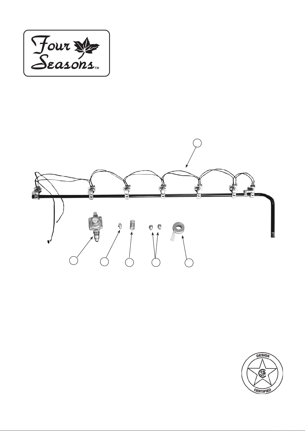
Part No. Qty Description
1 RCOZZ00341A 1 Main Burner Valve & Manifold Assembly with Valves (NG)
2 RPAZZ00002A 1 Thread Sealing Tape
3 RCOZZ00341A 1 Side Burner Orice (NG)
4 RCOZZ00117A 1 NG Regulator 3/8” NPT x 3/8” UNF
5 RCODZ00026A 2 Orice Back IR (NG)
6 RCODZ00052A 1 Connecting tube 3/8" NPT
3
6
5
2
Page 2
FSISLP Natural Gas Conversion Instructions
Tools needed:
Phillips head screwdriver
3/4” wrench
1/4” wrench or socket
Adjustable wrench
Wear golves to be protected from the sharp edges of the interior parts.
!
▲
NOTE: Make sure to use supplied pipe sealant on all non-ared ttings.
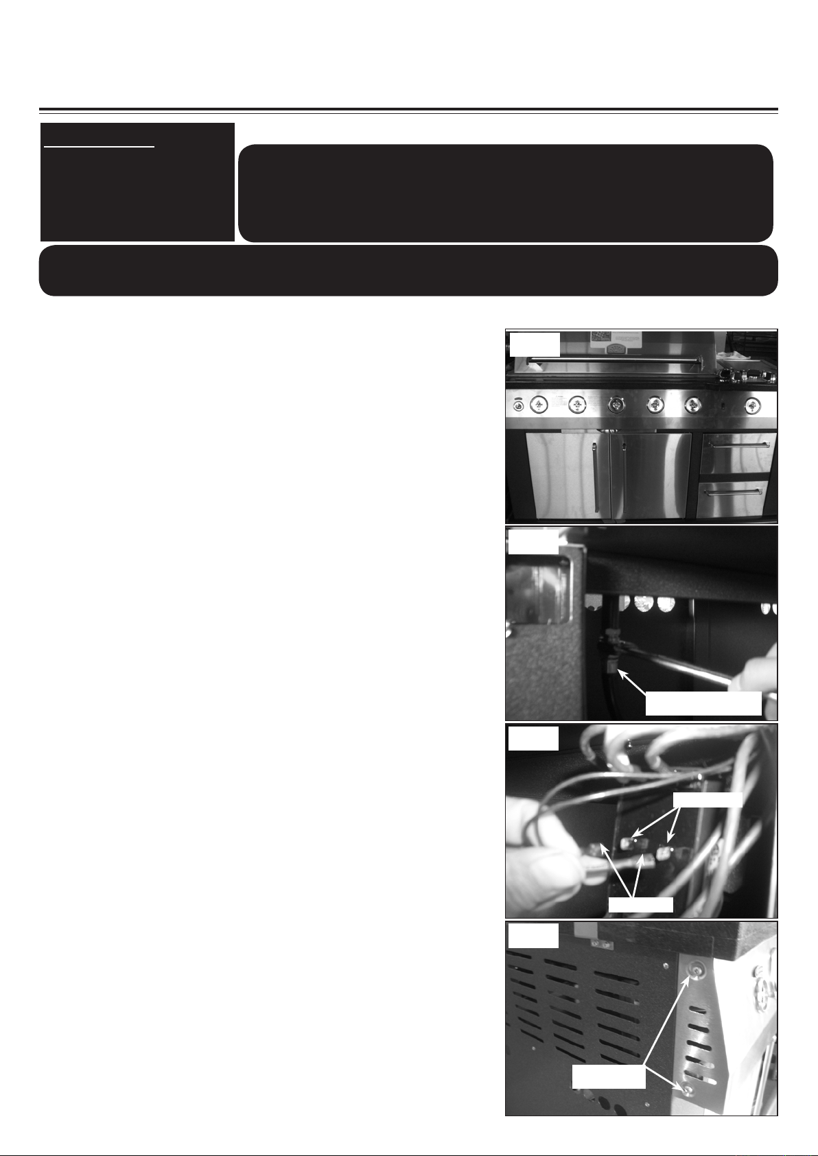
1. To get started, remove all the control knobs and set
aside. (See Fig. 1)
2. Use a 3/4” wrench to disconnect the regulator hose from
the manifold. (See Fig. 2)
Be sure gas supply is off, the knobs are in the off
position and the grill is cool.
!
WARNING
▲
Fig. 1
Fig. 2
3. Disconnect the two igniter wires from the outstand
terminal tabs as shown. (See Fig. 3)
4. Remove the two (2) phillips pan head screws from the left
side of the control panel. (See Fig. 4)
Regulator hose
Fig. 3
outstand tabs
Igniter wires
Fig. 4
Phillips Pan
Head Screws
Page 3
FSISLP Natural Gas Conversion Instructions
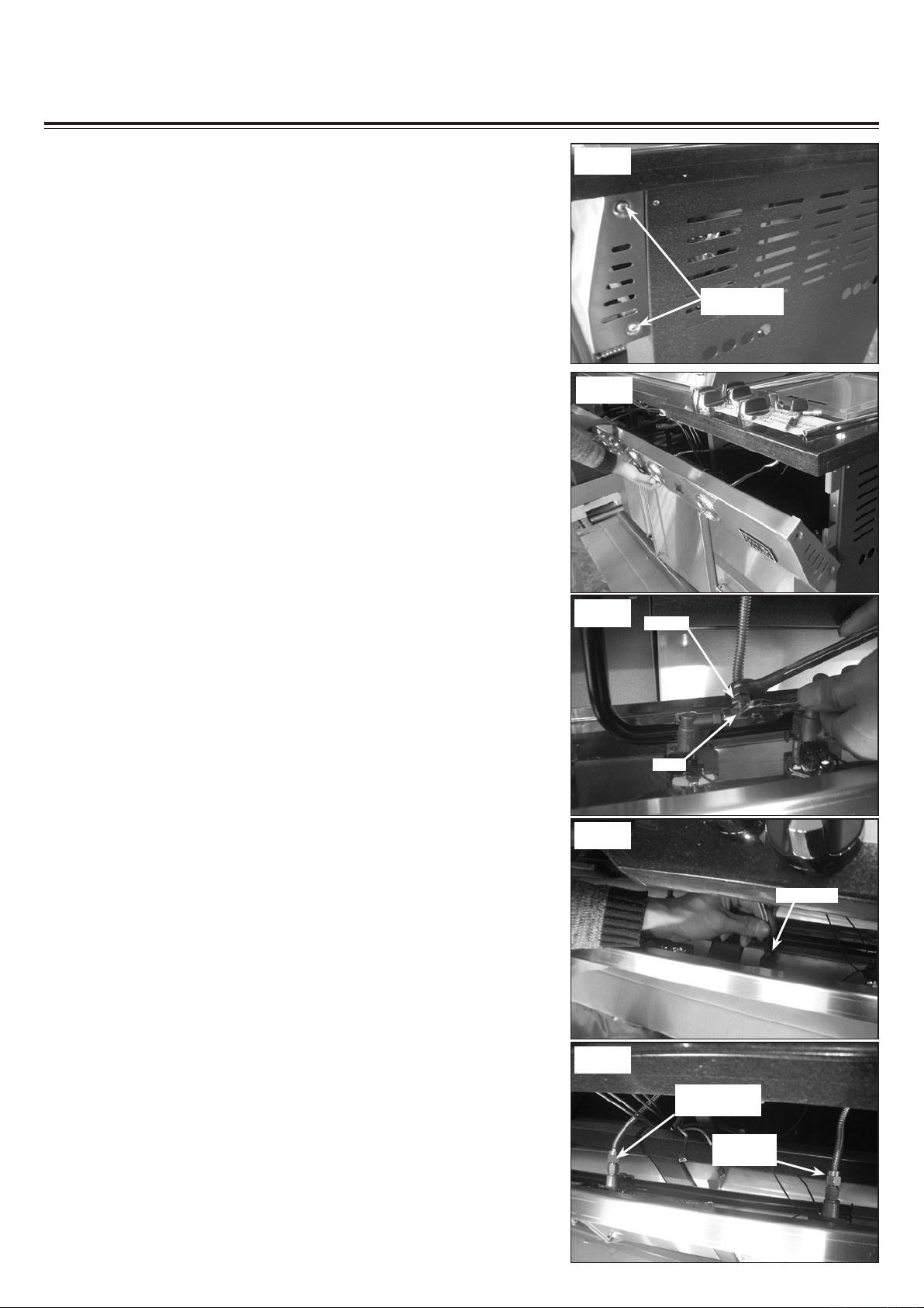
5. Remove the two (2) phillips pan head screws from the
right side of the control panel. (See Fig. 5)
6. Let a friend help you to carefully pull the front control
panel away from the grill a little and hold it. (See Fig. 6)
Fig. 5
Phillips Pan
Head Screws
Fig. 6
7. Use a wrench hold the elbow on the rear IR burner valve
and use another wrench to disconnect the ex line. (See
Fig. 7)
8. Disconnect the two light wires from the light switch. (See
Fig. 8)
9. Disconnect the ex line from the bottom IR burner valve
and side burner valve. (See Fig. 9)
Fig. 7
Fig. 8
Fig. 9
ex line
elbow
Light wires
bottom IR
burner ex line
Side burner
ex line
Page 4

FSISLP Natural Gas Conversion Instructions
10. Remove the front control panel, use a screw driver to
remove the twelve (12) screws securing the bezels and
the manifold in position. (See Fig. 10)
11. Replace the LP manifold with the one provided in the
NG conversion kit. Use the twelve screws removed in
step 10 to attach the bezels and manifold onto the front
control panel. (See Fig. 10 -11)
NOTE:
Make sure the “ OFF” position facing up as it was.
The igniter wires are preassembled, be careful DO
NOT remove the igniter wires from the valves on
the NG manifold.
Fig. 10
Fig. 11
12. Disconnect the ex line and side burner orice from the
side burner casting. (See Fig. 12)
13. Unscrew the LP side burner orifice from the flex line.
Replace it with the supplied NG side burner orice. (See
Fig. 13)
14. Connect the flex line and orifice onto the side burner
casting. (See Fig. 14)
Fig. 12
Orice
Fig. 13
Side burner orice
Fig. 14
Flex line
Orice
Flex line
Page 5

FSISLP Natural Gas Conversion Instructions
15. Place the front control panel back onto the grill and hold
it. Feed the two igniter wires through the hole on the
grill head bottom into the grill cabinet. Reconnect the
wires to the two outstand terminal tabs on the igniter
module. (See Fig. 15)
16. Reattach the flex lines to the rear IR burner valve,
bottom IR burner valve and side burner valve. (See
Fig. 16)
Note: Be careful, applying pressure to the elbow of
the valves may cause them to break.
Fig. 15
Fig. 16
Igniter wires
Rear IR burner
ex line
Bottom IR
burner ex line
Side burner
ex line
17. Slide the front control panel back in position. Make sure
the orices of the main burner control valves insert into
the main burner tubes. (See Fig. 17)
18. Use the four screws removed in step 4-5 to secure the
front control panel in position. (See Fig. 18)
19. Remove the bread warming rack, main cooking grates,
avor grids and set them aside. (See Fig. 19)
Fig. 17
Valve orice
Main burner
tube
Inside view underneath the front control panel
Fig. 18
Fig. 19
Page 6

FSISLP Natural Gas Conversion Instructions
20. Remove the two (2) screws securing the bottom IR
burner in position on the front. (See Fig. 20)
Fig. 20
21. Remove the rear one screw securing the bottom IR
burner in position. (See Fig. 21)
22. Pull the bottom IR burner out a little and disconnect the
ex line and igniter wire . (See Fig. 22)
Note: Make sure the igniter wire dose not fall into the
grill.
23. Hold the elbow on the bottom IR burner, then use the
supplied wrench to remove the LP orifice. Replace it
with the supplied NG orice and secure it. (See Fig. 23)
Fig. 21
Fig. 22
Flex line
Igniter wire
Fig. 23
Elbow
24. Place the bottom IR burner back in to the grill, reattach
the ex line and igniter wire, then set it back in position.
(See Fig. 24)
Orice
Fig. 24
Page 7

FSISLP Natural Gas Conversion Instructions
25. Use the three (3) screws removed in step 20-21 to
secure the bottom IR burner in position. (See Fig. 25)
26. Remove the six screws securing the wind shield and
rear IR cover in position. (See Fig. 26)
27. Grasp the rear IR cover and remove it. (See Fig. 27)
Fig. 25
Fig. 26
Fig. 27
28. Hold the elbow and use a wrench to remove the rear IR
burner LP orice. (See Fig. 28)
29. Replace it with the supplied NG orice and use the six
screws removed in step 24 to secure the rear IR burner
cover and wind shield in position. (See Fig. 29)
Fig. 28
Fig. 29
Page 8

FSISLP Natural Gas Conversion Instructions
30. Attach the 3/8" NPT connecting tube onto the manifold.
(See Fig. 30)
NOTE: Make sure to use supplied pipe sealant on
all non-ared ttings.
31. Attach the NG regulator onto the connecting tube. (See
Fig. 31)
Note: pay attention to arrow on the NG regulator
indicating direction of gas flow. The arrow should
point toward the grill.
NOTE: Make sure to use supplied pipe sealant on
all non-ared ttings.
Fig. 30
Fig. 31
Arrow on
the back of
regulator
32. Place the bread warmer, avor grids and main cooking
grates back in position, reattach all the knobs back in
position. (See Fig. 32)
Note: At the completion of the conversion, a leaktest
should be performed on all fittings.See Use and Care
manual for leak testing procedure.
The conversion is completed now.
Enjoy your grill safely.
Conversion Kit assembly picture
Fig. 32
 Loading...