

Sure Heat FS38 User Manual
NATURAL GAS CONVERSION KIT MANUAL
For Model FS388LP
FOR OUTDOOR USE ONLY
1
8 6
3
9
7
2
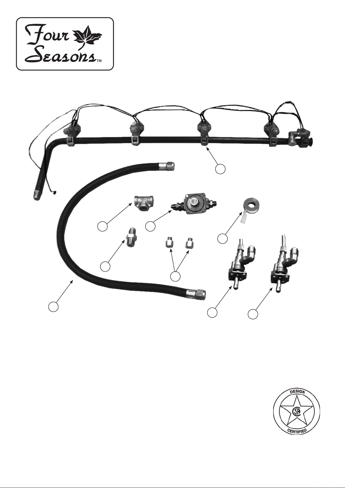
Part No. Qty Description
1 RCOZZ00343A 1 Main Burner Valve & Manifold Assembly with Valves (NG)
2 RCOZZ00117A 1 Hose 27" - 3/8" Flare Both Ends
3 RPAZZ00002A 1 Thread Sealing Tape
4 RCOZZ00344A 1 Side Burner valve (NG) - A
5 RCOZZ00350A 1 Side Burner valve (NG) - B
6 RCOZZ00117A 1 NG Regulator 3/8” NPT x 3/8” UNF
7 RCODZ00026A 2 Orice Back IR NG
8 RCOZA00021A 1 Tee Fitting - Galvanized 3/8" NPT
9 RCODZ00024A 1 Connector 3/8” NPT x 3/8” UNF
4
5
FS388LP Natural Gas Conversion Kit Instructions
Tools needed:
Phillips head screwdriver
3/4” wrench
1/4” wrench or socket
Adjustable wrench
Wear a glove to be protected from the sharp edges of the interior parts.
!
▲
NOTE: Make sure to use supplied pipe sealant on all non-ared ttings.
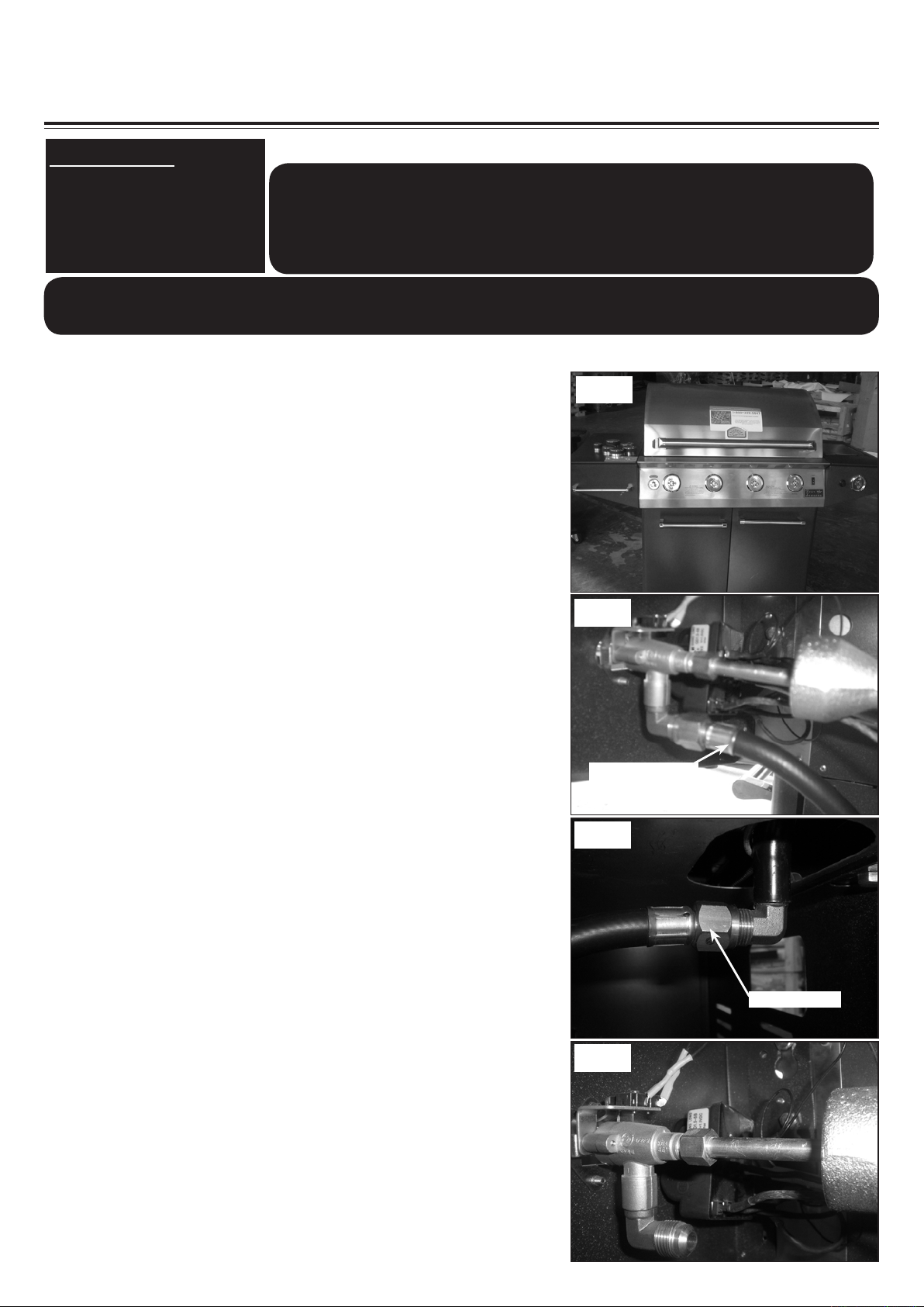
1. To get started, remove all the control knobs and set
aside. (See Fig. 1)
2. Use a 3/4” wrench disconnect the hose from the side
burner valve and pull the hose back into the cart. (See
Fig. 2)
Be sure gas supply is off, the knobs are in the off
position and the grill is cool.
!
WARNING
▲
Fig. 1
Fig. 2
3. Use a 3/4” wrench disconnect the other hose from the
manifold. (See Fig. 3)
4. Disconnect the eight (8) igniter wires from the igniter
module and two (2) wires from the side burner valve
underneath the side burner shelf. (See Fig. 4)
Regulator hose
Fig. 3
Regulator hose
Fig. 4
FS388LP Natural Gas Conversion Kit Instructions
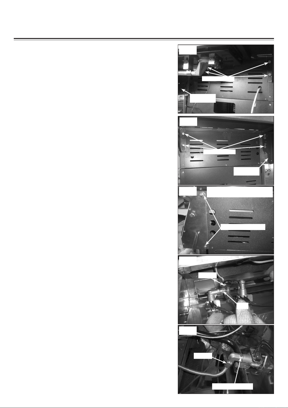
Fig. 5
5. Remove the self-tapping screw securing the right side
burner shelf in position. Loosen the four (4) hex head
screws on the right side of grill head assembly under the
side burner shelf by approximately 1/2". Then lift and
take off the side burner shelf and set aside. (See Fig. 5)
Fig. 6
6. Remove the self-tapping screw securing the left side
shelf in position. Loosen the four (4) hex head screws
on the left side of grill head assembly under the left side
shelf by approximately 1/2” . Then lift and take off the left
side shelf and set aside. (See Fig. 6)
Hex head Screws
self-tapping
Screw
Hex head Screws
self-tapping
Screw
7. Remove the four (4) phillips pan head screws at both
sides of the the front control panel. (See Fig. 7)
8. Let a friend help you to pull the front control panel out
and hold it. Use a wrench and hold the elbow on the rear
IR burner valve then use another wrench to disconnect
the ex line. (See Fig. 8)
Fig. 7
Fig. 8
Note: the other two screws located
at the same position on the left side
Phillips pan head screws
Flex line
Elbow
9. Use a wrench to disconnect the ex line from the bottom
IR burner valve. (See Fig. 9)
Fig. 9
Flex line
Bottom IR burner valve
 Loading...