

Page 1
TM
Tuscany
bbyy AAllttiimmaa
CS812 Natural Gas Conversion Manual
FOR OUTDOOR USE ONLY
3
4
6
1
7
5
2
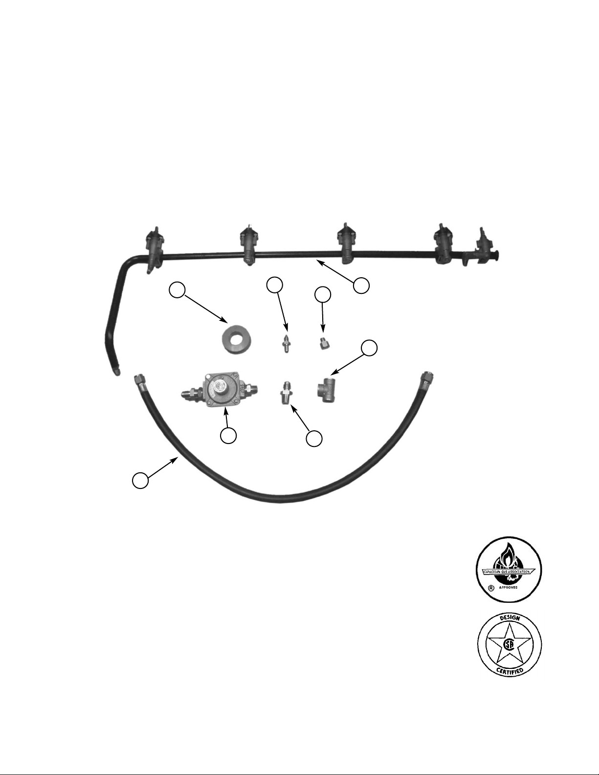
Part No. Qty Description
1 RCOZZ00345A 1 Main Burner Valve & Manifold Assembly with Valves (NG)
2 RCOZZ00117A 1 Hose 27" - 3/8" Flare Both Ends for Side Burner (NG)
3 RPAZZ00002A 1 Thread Sealing Tape
4 RCOZZ00346A 1 Side Burner Orifice (NG)
5 RCOZZ00117A 1 NG Regulator 3/8” NPT x 3/8” UNF
6 RCODZ00026A 1 Orifice Back IR NG"
7 RCOZA00021A 1 Tee Fitting - Galvanized 3/8" NPT
8 RCODZ00024A 1 Connector 3/8” NPT x 3/8” UNF
8
NOTE: Images in this manual may differ slightly from your grill.
Page 2

CS812 Natural Gas Conversion Instructions
Tools Needed:
Phillips head screwdriver
3/4” wrench
1/4” wrench or socket
Fig 1
Adjustable wrench
* 1/4” socket set with extension can also be used.
Be sure gas supply is off, the knobs are in the off
position and the grill is cool.
Wear a golve to be protected from the sharp
edges of the interior parts
To get started, remove all the control knobs and
set aside.
NOTE: Make sure to use supplied pipe sealant on
all non-flared fittings.
1. Use a 3/4” wrench disconnect the hose from the
side burner valve and pull the hose back into the
cart. (See Fig. 1)
2. Use a 3/4” wrench disconnect the other hose from
the manifold.(See Fig. 2)
Side burner
valve elbow
Regulator
Hose
Plastic Nut
Side burner
valve hose
Fig 2
Fig 3
3. Disconnect the igniter wires underneath the side
burner shelf. Then unscrew the push button cap on
the side burner shelf control panel, take out the
battery and unscrew the plastic nut to remov igniter
module.(See Fig. 3)
4. Loosen the four (4) hex head screws on the right
side of grill head assembly under the side burner
shelf for approximate 0.5” . Then lift and take off
the side burner shelf and set aside.(See Fig. 4)
5. Loosen the four (4) hex head screws on the left
side of grill head assembly under the left side shelf
for approximate 0.5” . Then lift and take off the left
side shelf and set aside.(See Fig. 5)
Fig 4
Hex Head Screws
Fig 5
Hex Head Screws
2
Page 3

CS812 Natural Gas Conversion Instructions
6. Remove the four (4) phillips pan head screws
at both sides of the the front control panel.
(See Fig. 6)
7. Let a friend help you to pull the front control
panel away from the grill and hold it. Using a
wrench, hold the elbow on the rear IR burner
valve and use another wrench to disconnect
the flex line. (See Fig. 7)
8. Take off the front control panel, use a screw
driver to remove the eight (8) screws securing
the bezels and the manifold in position.
(See Fig. 8)
9. Replace the LP manifold with the one provided
in the NG conversion kit. Use the eight screws
removed in step 8 to attach the bezels and
manifold onto the front control panel.
NOTE: Make sure the “ OFF” position facing up as it
was.
10.Attach the front control panel onto the grill
head assembly by insert the extended tube of
the manifold into the large slotted hole on the
grill head bottom. (See Fig. 9)
Flex line
Hold this
elbow
Phillps pan
head screws
Elbow on
the vale
Fig 6
Fig 7
Fig 8
11. Let a friend help you to hold the front control
panel and attach the rear IR burner flex line to
the rear IR burner control valve. (See Fig. 10)
12. Hold the elbow on the rear IR burner valve
and use a 3/4 wrench to tighten the flex line on
it. (See Fig. 7)
Note: Be careful, applying pressure to the elbow of
the valve may cause it to break.
Fig 9
Flex line
Fig 10
Elbow on
the vale
3
Page 4

CS812 Natural Gas Conversion Instructions
13. Push the front control panel back in position,
make sure the orifices of the valves insert into
the main burner tubes. Then use the four (4)
screws remvoed in step 6 on page 3 to secure
the front control panel in position. (See Fig. 11)
14. Remove the six (6) screws securing the rear IR
cover and wind shield in position. (See Fig. 12)
15. Take off the wind shield, grasp the rear infrared
cover and remove it from the grill. (See Fig. 13)
16. Use a wrench to remove the LP orifice on the
rear IR burner and replaced it with the NG orifice
provided in the conversion kit. (See Fig. 14)
17. Use the four (4) screws removed in step 14 to
reinstall rear IR cover in position, then use the
other two screws to reinstall the wind shield.
(See Fig. 12)
Control valve orifice
Wind shield
Main burner tube
Fig 11
Fig 12
18. Open the side burner door, remove the two
phillips pane head screws holding the side burner
orifice bracket in position. (See Fig. 15)
Rear IR orifice
Rear IR cover
Phillips pan
head screws
Fig 13
Fig 14
Fig 15
4
Page 5

CS812 Natural Gas Conversion Instructions
19. Unscrew the nut securing the bracket on the side
burner orifice. (See Fig. 16)
20. Use a wrench to remove the side burner orifice
from the flex line and replace it with the NG orifice
provided in the kit. (See Fig. 17)
21. Use the nut removed in step 19 to secure the
bracket onto the side burner orifice. (See Fig. 16)
22. Use the two screws removed in step 18 on page 4
to secure the bracket in position. (See Fig. 15 on
page 4)
23. Attach the left side shelf onto the grill head
assembly, and tighten the four (4) screws with a
wrench. (See Fig. 5 on page 2)
24. Attach the side burner shelf onto the grill head
assembly, and tighten the four (4) screws with a
wrench. (See Fig. 4 on page 2)
25. Reinstall the igniter module in position and feed
the battery with negative (-) end in first. reconnect
the igniter wires to the igniter module. It does not
matter which terminal tab is used when connecting
igniter wires.
Bracket
Side burner orifice
Fig 16
Nut
Fig 17
26. Attach the NG hose provided in the kit to the side
burner valve. (See Fig. 1 on page 2)
5
Page 6

CS812 Natural Gas Conversion Instructions
Note: Make Sure to use thread Sealing tape on
all non-flared fittings.
27. Attach the tee fitting to the manifold as shown.
Tighten with wrench. (See Fig. 18)
28 .Attach the Connector 3/8” NPT x 3/8” UNF to
the tee fitting as shown. Tighten with wrench.
(See Fig. 19)
29. Attach the NG regulator to the tee fitting.(See
Fig. 20)
Note: pay attention to arrow on the NG regulator indicating direction of gas flow. The arrow should point
toward the grill.
30. Attach the other end of the side burner hose to
the flare fitting on the side of the tee connector.
(See Fig. 21)
31. Reattach all the control knobs in position.
Note: At the completion of the conversion, a leak
test should be performed on all fittings. See Use
and Care manual for leak testing procedure.
Installation is now complete.
Enjoy your grill safely.
Fig 18
Fig 19
Fig 20
arrow on
the back of
regulator
Conversion Kit Assembly Picture
Fig 21
6
 Loading...