

Page 1

Bottom and Back Side
n Bottom
n Back
Star-shaped screw hole for fixing a body to a metal bracket
3 pin connector – wiegandoutput
5 pin connector – power and RS485
4 pin connector – ethernet(TCP/IP)
7 pin connector – digital input and relay output
DIP switch – RS485 termination setting
(Refer to “RS485 Connection” pages for details)
ⒸCopyright 2007Suprema Inc.
11
Page 2

Product Dimension
160
50
160
37
150
40
135
Metal BracketFront Side
(unit : mm)
ⒸCopyright 2007Suprema Inc.
12
Page 3

Cables and Connectors
Power and RS485
TCP/IP
Wiegandoutput
Digital Inputs and Relay output
PIN PIN DESCRIPTION WIRE
1 POWER +12V RED
2 POWER GND BLACK
3 RS -485 GND GRAY
4 RS -485 TRX+ BLUE
5 RS -485 TRX- YELLOW
PIN PIN DESCRIPTION WIRE RJ45 PIN
1 TX + YELLOW 6
2 TX - GREEN 3
3 RX + RED 2
4 RX - BLACK 1
PIN PIN DESCRIPTION WIRE
1 WIEGAND DATA0 GREEN
2 WIEGAND DATA1 WHITE
3 WIEGAND GND BLACK
PIN PIN DESCRIPTION WIRE
1 SW1 INPUT YELLOW
2 SW1 GND BLACK
3 SW2 INPUT GREEN
4 SW2 GND BLACK
5 RELAY NORMAL CLOSE ORANGE
6 RELAY COMMON BLUE
7 RELAY NORMAL OPEN WHITE
ⒸCopyright 2007Suprema Inc.
13
Page 4

Installation of Wall-mount Bracket
n Fix wall mount bracket on a wall using wall mounting
screws
Wall mounting
screws
n Hook BioEntryPlus on the wall mount bracket
n Fix BioStation and wall mounting bracket using a star
shape screw.
Star-shaped
screw
Star-shaped
wrench
ⒸCopyright 2007Suprema Inc.
14
Page 5

Power Connection
n Recommended power supply
l 12V ± 10%, at least 1500mA.
l Comply with standard IEC/EN 60950-1.
l To share the power with other devices, use a power supply with higher current ratings.
15
ⒸCopyright 2007Suprema Inc.
Page 6

Ethernet Connection
ⒸCopyright 2007Suprema Inc.
16
Page 7

Ethernet Connection (Direct connection with PC)
n To connect BioEntryPlus with a PC directly, connect both devices with a straight CAT-5
cable. As the BioEntryPlus supports auto MDI/MDIX feature, it is not necessary to usea
crossover type cable.
ⒸCopyright 2007Suprema Inc.
17
Page 8

RS485 Connection for Host Communication
ⒸCopyright 2007Suprema Inc.
18
Page 9

RS485 Connection for Secure I/O
n Max number of devices
l Maximum numbers of devices in an RS485 loop are two(2) devices (BioStation or BioEntry
Plus) and four(4) Secure I/Os
19
ⒸCopyright 2007Suprema Inc.
Page 10

Relay Connection – Fail safe lock
ⒸCopyright 2007Suprema Inc.
20
Page 11

Relay Connection – Fail secure lock
ⒸCopyright 2007Suprema Inc.
21
Page 12

Relay Connection -Automatic door
ⒸCopyright 2007Suprema Inc.
22
Page 13
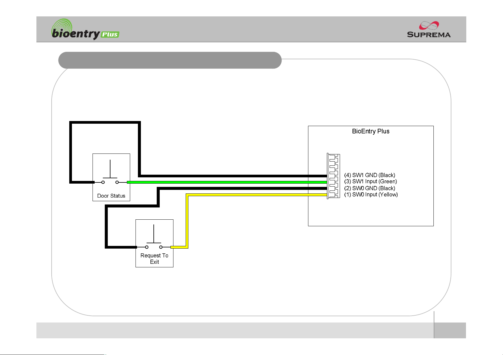
Digital Input Connection (RTE, Door sensor)
ⒸCopyright 2007Suprema Inc.
23
Page 14

Digital Input Connection (Alarm, Emergency sw)
ⒸCopyright 2007Suprema Inc.
24
Page 15

WiegandOutput
ⒸCopyright 2007Suprema Inc.
25
Page 16

Installation Reference 1 -Stand alone
Door Sensor
BioEntryPlus
Door Lock
LAN
Exit Button
Enroll ScannerPC
26
ⒸCopyright 2007Suprema Inc.
Page 17

Installation Reference 2 – Secure
Door Sensor
RS485
BioEntryPlus
Door Lock
LAN
Exit Button
Secure I/O
Enroll ScannerPC
27
ⒸCopyright 2007Suprema Inc.
Page 18

Installation Reference 3 – Network
Door Zone 1 (Anti passback)
RS485 RS485
BioStation BioEntryPlus BioEntryPlus Secure I/O
LAN
BioStation Secure I/O BioEntryPlus
RS485
Door Zone 2 (Anti passback)
Exit Button
PC Server
PC Client
PC Client
ⒸCopyright 2007Suprema Inc.
Enroll Scanner
28
Page 19

Electrical Specification
Min. Typ. Max. Notes
Power
Voltage (V) 10.8 12 13.2 Use regulated DC power adaptor only
Current (mA) - 250
Switch Input
VIH(V) - TBD -
VIL(V) - TBD
Pull-up resistance (Ω) - 4.7k - The input ports are pulled up with 4.7k resistors
TTL/WiegandOutput
VOH(V) - 5 -
VOL(V) - 0.8 -
Pull-up resistance (Ω) - 4.7k -
Relay
Switching capacity (A) - -
Switching power
(resistive)
Switching voltage (V) - -
- -
0.3
30W
37.5VADCAC
110
125
The outputs ports are open drain type, pulled up with 4.7k resistors
internally
1
30V DC
125V AC
DC
AC
29
ⒸCopyright 2007Suprema Inc.
Page 20

Troubleshooting
n Fingerprint can not be read well or it takes too long.
l Check whether a finger or fingerprint sensor is stained with sweat, water, or dust
l Retry after wiping off finger and fingerprint sensor with dry towel.
l If a fingerprint is way too dry, blow on the finger and retry.
n Fingerprint is entered but authorization keeps failing.
l Check whether the user is restricted by door zone or time zone.
l Inquire of administrator whether the enrolled fingerprint has been deleted frinthe device for some
reason.
n Authorized but door is not opened.
l Check whether the time is set as lock time.
l Check whether an antipassback mode is in use. In antipassback mode, only who entered can exit.
n Device doesn’t operate though power is connected.
l Check whether a device and a bracket is well connected to each other. If not, a tamper switch is
activated and the device doesn’t work.
ⒸCopyright 2007Suprema Inc.
30
Page 21

Device cleaning
n Wipe out machine surface with dry towel or cloth.
n In case there is dust or impurities on the sensor of the BioStation, wipe off the surface with
dry towel.
n Note that if the sensor is cleaned by detergent, benzene or thinner, surface is damaged and
fingerprint can’t be entered.
ⒸCopyright 2007Suprema Inc.
31
Page 22

FCC Rules
Caution
Warning
Information to User
l Changes or modifications not expressly approved by the manufacturer
responsible for compliance could void the user's authority to operate the
equipment.
l This device complies with part 15 of the FCC Rules. Operation issubject to
the following two conditions: (1) This device may not cause harmful
interference, and (2) this device must accept any interference received,
including interference that may cause undesired operation.
l This equipment has been tested and found to comply with the limit of a Class
B digital device, pursuant to Part 15 of the FCC Rules. These limits are
designed to provide reasonable protection against harmful interference in a
residential installation. This equipment generates, user and canradiate radio
frequency energy and, if not installed and used in accordance with the
instructions, may cause harmful interference to radio communications.
However, there is no guaranteeethat interference will not occur in a particular
installation; if this equipment does cause harmful interference to radio or
television reception, which can be determined by turning the equipment off
and on, the user is encouraged to try to correct the interference by one or
more of the following measures:
1. Reorient / Relocate the receiving antenna.
2. Increase the separation between the equipment and receiver.
3. Connect the equipment into an outlet on a circuit difference from that
to which the receiver is connected.
4. Consult the dealer or an experienced radio/TV technician for help
ⒸCopyright 2007Suprema Inc.
32
Page 23

Suprema Inc.
16F Parkview Office Tower, Jeongja-dong, Bundang-gu,
Seongnam, Gyeonggi, 463-863 Korea
E-mail : support@supremainc.com
Website : www.supremainc.com
Functions and specifications of the product are subject to changes without notice due to quality
enhancement or function update. For any inquiry on the product, please contact Suprema Inc.
 Loading...