

Supersonic Franky Instruction Manual

Instruction
Manual

2
Table of Contents
1 ACKNOWLEDGEMENTS 4
2 INTRODUCTION 5
3 INSTRUCTIONS FOR USE 6
4 SYSTEM REQUIREMENTS 7
5 TECHNICAL SPECIFICATIONS 7
Overview 7
VGA Connector 8
6 DEVELOPER INFORMATION 9
General information 9
Video processor 9
Audio processor 9
Game controller 10
Memory mapper 10
Conversion tool 10
Modifying MSX Bios to reroute VDP output to Franky 14
7 VDP DOCUMENTATION 15
Introduction 15
VDP ports 15
VDP Programming 16
Control port 16
VDP register write 17
Data port 17
Status flags 18
Color RAM 19
Display modes 19
Register reference 21
Patterns 25
Background 25
Horizontal scrolling 25
Vertical scrolling 26
Sprites 27
Table parsing 28

3
Display timing 29
Display details 30
H counter 31
Interrupts 32
Frame interrupts 33
Line interrupts 33
Miscellaneous 34
8 PROGRAMMABLE SOUND GENERATOR DOCUMENTATION 35
Accessing the SN76489 from software 35
SN76489 registers 35
Volume registers 36
Tone registers 36
Noise register 36
Example program 37
SN76489 register writes 37
How the SN76489 makes sound 39
Tone channels 40
Noise channel 40
The Linear Feedback Shift Register 41
The external Linear Feedback Shift Register 41
Volume/attenuation 42
The imperfect SN76489 43
Playing samples on the PSG 44
Pulse Code Modulation 44
Advanced PCM 45
Pulse Width Modulation 45

4
Acknowledgements
SuperSoniqs would like to thank the following people first, because without them this
card wouldn’t be a reality:
Ronnie van der Kolk – www.rklok.nl , for providing us with broken Sega Mark
III consoles so we could build our first prototypes. Luckely the VDP’s still worked.
Rob Hiep – www.msx.ch , he provided us with cartridge cases so we could
actually give the Franky PCB a place to live in.
Lino Lampers - members.chello.nl/mlampers/ , for providing us with the vga
connectors and video memory ic’s. My backyard looked like Zombieland
afterwards.
Bas Kornalijnslijper – www.bas-ditta.info , for arranging the assembly of our
first batch.
Maxim Zhao – www.smspower.org , for helping out in general and for giving us
permission to use his texts about the audio part of the Sega A/V processors and
modify them.
Charles MacDonald - http://cgfm2.emuviews.com/, for giving us permission to
use his VDP documentation and modify them.
Albert Beevendorp - www.bifi.msxnet.org , for testing and writing programs

5
Introduction
First of all: congratulations with your new purchase. Franky is a powerful new video and
audio extension card for MSX computers. The core component on this hardware is a
combined video and audio processor that is also used by the Sega Mark III and Sega
Master System game consoles. It has his own video memory, a volume output adjuster
(on the PCB) and the output connector is a standard 15 pin VGA connector that has been
made pin compatible with the One Chip MSX, so you can use existing OCM cables to
connect Franky to your monitor or TV with RGB input support. Franky also features a
PAL/NTSC encoder that can ensure compatibly with the CVBS (composite video) standard
in your country. This might be convenient if your monitor or TV has support for CVBS
only. Please see chapter ‘Technical Specifications’ for more details.
Franky is not a Sega console on its own. Although it can potentially run most programs
made for the 8-bit Sega consoles mentioned, Franky still needs an MSX computer to
operate. Franky uses his own addresses for accessing the video/audio processor.
Therefore, existing Sega homebrew software needs to be converted with our software
converter. Testing shows that about 75% of programs tested will run without problems
after using the converter, without any further adjustments. This number surely will rise
in time when more developers start using Franky. We expect more tools, useful programs
and new games in the near future. If you start a new project with Franky, please let us
know!
If you need support while developing for Franky these places are a great start:
supersoniqs.wordpress.com Our website where we will post new information on our
products, keep our technical documentation and tools up to date and inform you about
new developments.
www.smspower.org Great site about the Sega Master System and Mark III. It has a lot of
developer information on Sega hardware. It features an active community with extensive
forum and some great people with a lot of technical knowledge about Sega software and
hardware.
www.msx.org Biggest MSX community site on the internet with more than 5000
members. Please check the forum and post your questions and remarks in the cross
development section.
6
Also, there are IRC channels where MSX developers and users meet. These are:
#MSXdev on Rizon (irc.rizon.net)
#MSX on Undernet (eu.undernet.org)
#MSX on Rizon (irc.rizon.net)
To connect to IRC channels you need a dedicated IRC client like mIRC for windows.
More information on IRC can be found at Wikipedia: http://en.wikipedia.org/wiki/Irc
Have great fun with your new hardware and thank you for exploring new possibilities on
MSX with Franky!
Instructions for use
Franky, like most cartridges for your MSX computer, does not like being inserted in your
MSX cartridge slot when the MSX is powered on. Please make sure that your MSX is
powered off when inserting or removing Franky. Else you might irreversibly damage
Franky and / or your MSX computer.
Franky consist out of more than 45 assembled electronic components. So please be
gentle when you move or store Franky.
Besides an MSX, Franky also needs a cable to hook up the shared video / audio out
connector to your monitor or TV. This cable is not part of your purchased product
package because there are different standards for RGB and CVBS connectors. Please
check the chapter “Technical specifications’ to examine the pin layout diagram of
Franky’s output connector to build your own cable. You can also order a custom made
cable online at www.bas-ditta.info, if your input connectors are not too exotic.
When Franky is connected to your MSX and everything is powered on, you can start
using Franky with the software converter, program your own programs or adjust your
existing code for use on the Franky hardware. Please see chapter ‘Developer information’
for more information how to program for Franky.
Please note that when using the software converter to load programs your
joystick needs to be in joystick port 2. MSX game port 2 is port 1 in Sega programs.

7
System requirements
Franky works on any MSX, with or without disk drive. Still, if you want to use the
software converter and load converted Sega programs we recommend using an MSX with
at least a connected disk drive. For converted Sega programs the same rule apply as
when using MSX programs that are converted from cartridge: you need more memory
than the original size of the program. We recommend using a MSX with disk drive and
512KB or more. Of course, if you are programming your own software you are not bound
to any requirements, except those you really need for your program.
If you want to use both the RGB output of your MSX computer and the RGB output
possibility of the VGA connector on Franky at the same time, two monitors (or a monitor
and a TV) or switch box are needed. However, if your monitor or TV supports selectable
RGB and CVBS input, you can choose to connect the MSX to your RGB input, and Franky
to the CVBS input (or vice versa, depending on which output possibilities your MSX
provides), thus eliminating the need for a dual monitor setup.
Technical specifications
Overview
Sega A/V Processor: model 315-5124 or 315-5246
Graphics: VDP (Video Display Processor) derived from Texas Instruments TMS9918
32 simultaneous colors available (two separate palettes with 16 colors out of 64)
Screen resolutions 256×192 and 256×224. PAL also supports 256×240
3.546893 MHz for PAL/B/G (through 4-pin DIP crystal oscillator)
3.579545 MHz for NTSC (clock provided by MSX)
3.575611 MHz for PAL-M (by replacing the 4-pin DIP oscillator, not included)
8×8 pixel characters, max 463
8×8 or 8×16 pixel sprites, max 64
Horizontal, vertical, and partial screen scrolling
Sound (PSG): Texas Instruments SN76489 (Build in VDP)
4 channel mono sound (3 Square Waves, 1 White Noise)
3 tone generators, 10 octaves each, 1 white noise generator
Video RAM: 128kb
Build in PAL/NTSC encoder: model Analog Devices AD722, AD724 or AD725
8
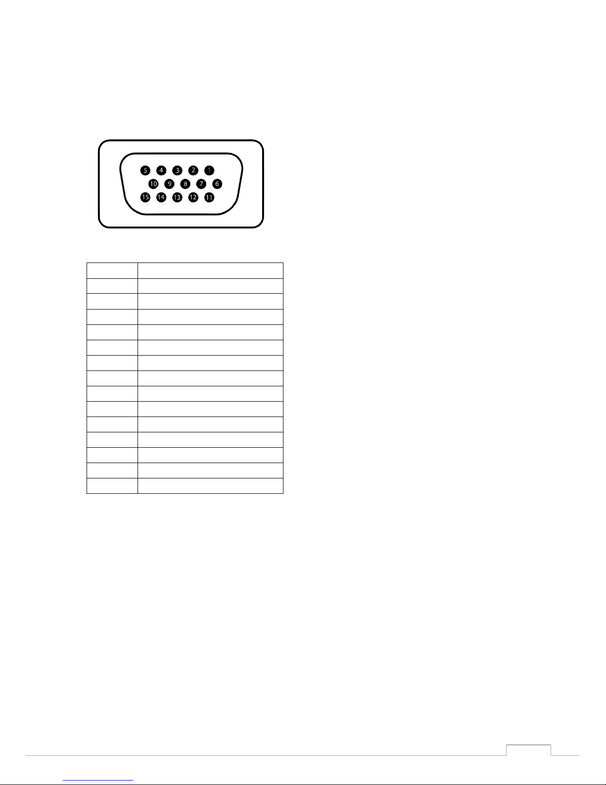
VGA Connector
The connector used for the video and sound output of Franky is a 15 pin standard VGA
connector
The pin layout (seen as looking towards the connector) is as follows:
Pin 1
Red
Pin 2
Green
Pin 3
Blue
Pin 4
Not connected
Pin 5
Ground
Pin 6
Red ground
Pin 7
Green ground
Pin 8
Blue ground
Pin 9
Not connected
Pin 10
Ground
Pin 11
Not connected
Pin 12
Not connected
Pin 13
CVBS (Composite) output
Pin 14
Audio
Pin 15
Not connected
Please note that although we used a VGA connector for durability, you can not use this
connector to connect the Franky VDP card to a VGA monitor.

9
Developer information
General information
The Sega and MSX systems have a lot in common and this makes it possible to convert
software from Sega to MSX (and vice versa). Both systems use a Z80 CPU and have the
same kind of memory mapping. Even the VDP is partly compatible to the MSX1 VDP, but
with more options. The original Sega Audio / Video processor is used in Franky. MSX
needs to handle the remaining parts. This being the game controller; sound and memory
mapping.
Originally the I/O addresses used in the Sega system are occupied in the MSX system;
therefore the Sega VDP places data on different addresses which are unused in the MSX
system. The VDP and PSG of the Sega are in the same chip, in a way that the difference
between the I/O of PSG and VDP is &H40 by hardware. This reduced our choices of
assigning I/O addresses while designing Franky. To maintain MSX compatibility we have
chosen an I/O address of &H88 for the VDP and &H48 for PSG.
The Franky card itself uses the I/O addresses &H88, &H89, &H48 and &H49. In the Sega
system the game controller uses I/O &HDC and &HDD and if an FM-Pac is available it
uses &HF0 to &HF2. All these I/O addresses must be changed to run a Sega program on
MSX, this is also the case for the memory mapping which is done at memory addresses
in the Sega system and I/O addresses in the MSX system
Video processor
The Sega VDP is located at &H88 and &H89 in Franky, this used to be &HBE and &HBF in
the Sega Master System console. This means all OUT, IN, OUTI, OTIR, INI and INIR
instructions to &HBE or &HBF must be changed to &H88 and &H89.
Audio processor
The same counts for the audio processor. All OUT, IN, OUTI, OTIR, INI and INIR
instructions accessing &H7E or &H7F (the original Sega addresses), must be changed to
&H48 and &H49.
10
Game controller
The Sega game controller is located at I/O &HDC for game pad 1 and I/O &HDD for game
pad 2. It turns out that all bits of game pad 1 are compatible with MSX joystick 1. Game
pad 2 requires some computations and bit shifting to make it working on MSX joystick
port 2. If the MSX PSG is set up for register 14, a read from I/O &HA2 returns the same
data as a read from &HDC in the Sega system. So all IN, INI and INIR instructions
accessing &HDC, should be changed to &HA2 and before executing the game, OUT
&HA0,14 to set up the MSX PSG.
Memory mapper
The Sega rom is mapped by writing the page number to memory address &HFFFD,
&HFFFE and &HFFFF, this indicates which 16k part of the rom should be readable at
address &H0000, &H4000 and &H8000. In the MSX system the ram memory is mapped
the same way, but instead of writing the page number to memory, the page number is
written to I/O addresses &HFC, &HFD and &HFE.
Conversion tool
This conversion tool loads the ROM image into the MSX memory starting from the first
page and replaces the following:
Load Sega into RAM, find & replace:
POKE &HFFFD OUT &HFC
POKE &HFFFE OUT &HFD
POKE &HFFFF OUT &HFE
OUT &HBE OUT &H88
OUT &HBF OUT &H89
OUT &H7E OUT &H48
OUT &H7F OUT &H49
OUT &HDC OUT &HA2
OUT &HF0 OUT &H7C
OUT &HF1 OUT &H7D
OUT &HF2 OUT &H7E
32 FF FF -> 00 D3 FE
32 FE FF -> 00 D3 FD
32 FD FF -> 00 D3 FC
32 FC FF -> Switch to empty RAM page, no replace

11
Search for
Step back 32 bytes, find & replace:
Search for OUT:
INI, OUTI, OTIR, I/O (C) ED A2 / ED A3 / ED B3
/ ED 41
0E 7E -> 0E 48
0E 7F -> 0E 49
0E BE -> 0E 88
0E BF -> 0E 89
0E DE -> No replace
0E DF -> No replace
0E F0 -> 0E 7C
0E F1 -> 0E 7D
01 7E -> 01 48
01 7F -> 01 49
01 BE -> 01 88
01 BF -> 01 89
01 DE -> No replace
01 DF -> No replace
01 F0 -> 01 7C
01 F1 -> 01 7D
D3 7E -> D3 48
D3 7F -> D3 49
D3 BE -> D3 88
D3 BF -> D3 89
D3 DE -> No replace
D3 DF -> No replace
D3 F0 -> D3 7C
D3 F1 -> D3 7D
12
Search for IN:
After the ROM is loaded, the upper 16k of the Z80 memory space is set to the highest
page in the mapper (OUT &HFF,&HFF). This part acts like the RAM of the Sega system.
Then the memory is initialized by switching the right pages to the Z80 memory (OUT
&HFC,0:OUT &HFD,1:OUT &HFE,2), finally a jump to address &H0000 reinitializes all
hardware and executes the game.
This is a very quick and simple conversion tool and due to the find and replace to the
program some display data or table might be damaged (that’s probably also the reason
that not all games are working as they should). The best results are achieved by
manually converting, disassembling, visual recognizing the difference between code and
data and understanding the meaning of the found OUT instructions.
To get full compatibility, some points should be implemented as well, e.g. if bit 3 of
&HFFFC is set, an SRAM is mapped at &H8000-&HBFFF. The second game pad needs a
subroutine to give the right values when the program reads I/O &HDD and the detection
of the availability of the FM chip is not in the converter as well.
Code example for disabling the MSX VDP interrupts and adding support for joystick port 1
If you want to load manually converted Sega binary programs, you need to disable the
MSX VDP interrupts.
By only setting OUT &HA0,14 before executing the program and replacing IN (&HDC) by
IN (&HA2) inside the binary, joysticks on joystick port 1 works fine. The example code
below is quick and dirty code and only works on MSX computers where the RAM is
located in slot 3-2:
DB 7E -> DB 48
DB 7F -> DB 49
DB BE -> DB 88
DB BF -> DB 89
DB DC -> DB A2
DB DD -> Read from Gamepad2, no replace
DB DE -> No replace
DB DF -> No replace
DB F2 -> No replace
13
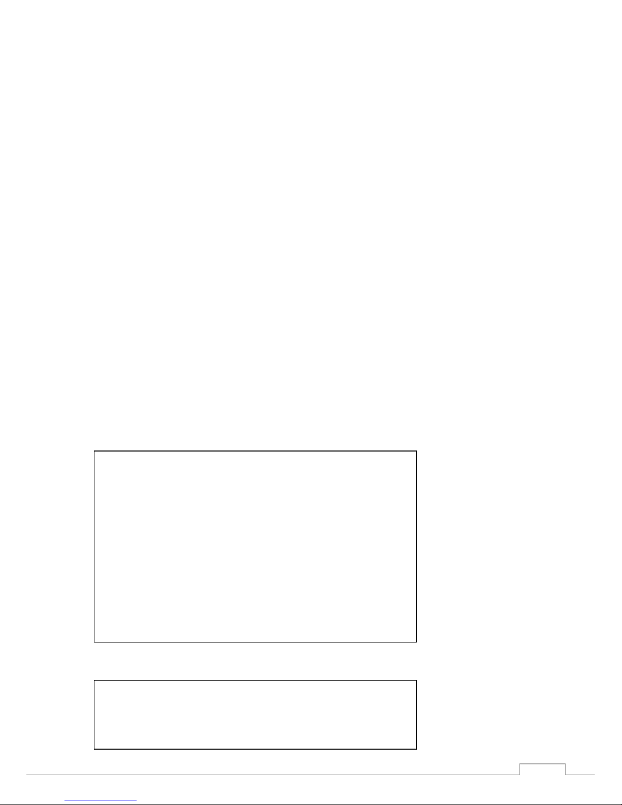
This is the disassembled code in the data lines disassembled:
The instruction to disable interrupts is different for V9938/58 than for TMS9918. The
hardware Z80 interrupt acknowledge is not used in MSX, and, to our current knowledge,
neither in SMS. The 'normal' Z80 application will listen to the IORQ and M1 signals, when
both are low, the Z80 indicates that the interrupt is heard and will be processed as soon
the software allows it. In MSX the interrupt flag of the VDP must be cleared when an
interrupt occurs otherwise the VDP will keep the INT line low so when the Z80 exits the
interrupt service routine and enables the interrupt, it will jump directly to the ISR again.
DI
LD A,&HFF ;All Z80 memory space to the mapper
OUT (&HA8),A
LD A,(&HAA) ;Choose sub slot for mapper
LD (&HFFFF),A
LD A,4 ;Start of 1st part of 32k rom
OUT (&HFC),A
LD A,5 ;2nd part of 32k rom
OUT (&HFD),A
OUT (&HFE),A
JP &H0000 ;Start program
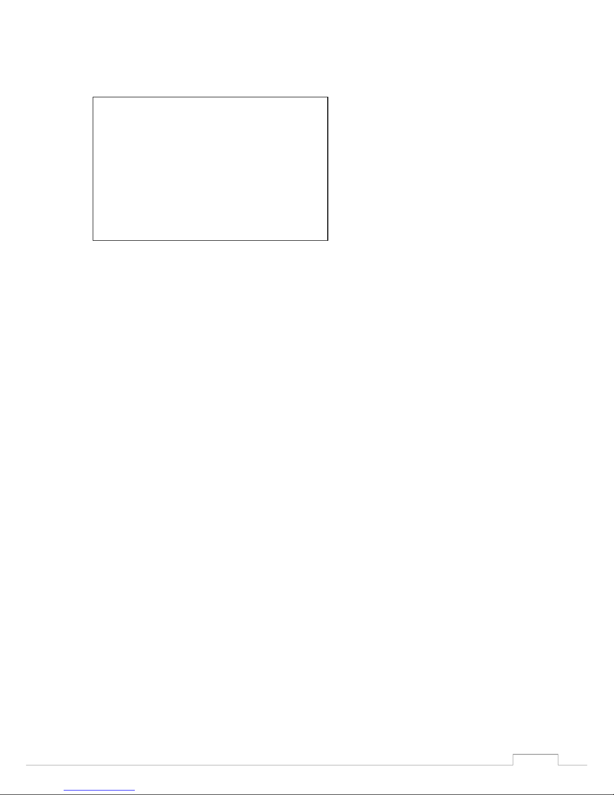
10 IF PEEK(&HF677)<>&HC0 THEN POKE &HF677,&HC0:POKE &HC000,0:RUN
"HOMEBREW.BAS"
20 OUT &HFE,4:BLOAD "HOMEBR1.BIN"
30 OUT &HFE,5:BLOAD "HOMEBR2.BIN"
35 OUT &HA0,14
36 VDP(0)=VDP(0) AND 207
37 VDP(1)=VDP(1) AND 219
40 A=&HC800
50 DEF USR=&HC800
60 READ D$:IF D$="*" THEN A=USR(0)
70 POKE A,VAL("&H"+D$):A=A+1:GOTO 60
80 DATA
F3,3E,FF,D3,A8,3E,AA,32,FF,FF,3E,04,D3,FC,3E,05,D3,FD,D3,FE,C3,00,00,*
14
Modifying MSX Bios to reroute VDP output to Franky
It is possible to modify an existing first generation MSX Bios to use the Franky VDP card
as the default for MSX VDP output. The Sega VDP is for a large part TMS9919
compatible. On MSX1 and MSX2 computers this means that you have to replace the
existing MSX Bios (e)proms in your computer.
You have to modify an existing bios so that every I/O to the VDP at &H98 or &H99 is set
to &H88 and &H89. Fortunately most MSX games are programmed a very descent way,
almost everything is done via the BIOS or the actual VDP address is read out from
address 6 and 7.
If you have a MSX Turbo R things are a lot easier. The BIOS of the TR is very easy to
modify and it remains modified until you give a hard reset. The trick here is to put the TR
in R800 mode, overwrite rampage 28 and 29 with the modified BIOS and switch to
R800D mode or Z80D. As you might know a TR has 64k less memory in DRAM mode
because it uses 64k for BIOS, in fact the BIOS is mirrored to DRAM while DRAM is much
faster. This mirror seems to be copied at startup only, later on while switching between
R800 and R800D only some hardware routes are changed inside the S1990. If we in the
meantime update the mirror, we get an updated BIOS in R800D mode.
A very nice feature of the TR is that there is also a Z80D mode, not supported by the
default BIOS but it is very easy. Just try in BASIC, when the TR is in Z80 mode (by
default Z80 ROM mode) you will find the BIOS at address &H8000 if you give an OUT
&HFE,12. This is now 'free memory' and in ROM mode the full 256k is available:
For an TR ST the mirror starts at 12 (OUT &HFE,12), for an GT it is 28.
? PEEK(0) 'Read the first byte of the BIOS
243
Ok
OUT &HFE,12:? PEEK(&H8000) 'Switch BIOS mirror to address &H8000
243
Ok
POKE &H8000,123 'Change BIOS mirror
Ok
OUT &HE4,6:OUT &HE5,32 'Switch to unsupported Z80 DRAM mode
Ok
? PEEK(0)
123
Ok
 Loading...