

Page 1

SUPER
AOC-SOZCR1
AOC-LPZCR1
AOC-LPZCR1/AOC-SOZCR1
All-In-One ZCR Card
USER'S GUIDE
Rev. 1.0a
Page 2

AOC-LPZCR1/AOC-SOZCR1 User's Guide
The information in this User’s Guide has been carefully reviewed and is believed to be accurate.
The vendor assumes no responsibility for any inaccuracies that may be contained in this document,
makes no commitment to update or to keep current the information in this manual, or to notify any
person or organization of the updates.
Please Note: For the most up-to-date version of
this manual, please see our web site at www.supermicro.com.
SUPERMICRO COMPUTER reserves the right to make changes to the product described in this
manual at any time and without notice. This product, including software, if any, and documentation may not, in whole or in part, be copied, photocopied, reproduced, translated or reduced to any
medium or machine without prior written consent.
IN NO EVENT WILL SUPERMICRO COMPUTER BE LIABLE FOR DIRECT, INDIRECT, SPECIAL,
INCIDENTAL, OR CONSEQUENTIAL DAMAGES ARISING FROM THE USE OR INABILITY TO
USE THIS PRODUCT OR DOCUMENTATION, EVEN IF ADVISED OF THE POSSIBILITY OF
SUCH DAMAGES. IN PARTICULAR, THE VENDOR SHALL NOT HAVE LIABILITY FOR ANY
HARDWARE, SOFTWARE, OR DATA STORED OR USED WITH THE PRODUCT, INCLUDING
THE COSTS OF REPAIRING, REPLACING, INTEGRATING, INSTALLING OR RECOVERING
SUCH HARDWARE, SOFTWARE, OR DATA.
Any disputes arising between
manufacturer and customer shall be governed by the laws of Santa Clara County in the State of
California, USA. The State of California, County of Santa Clara shall be the exclusive venue for the
resolution of any such disputes. Supermicro's total liability for all claims will not exceed the price
paid for the hardware product.
Unless you request and receive written permission from SUPER MICRO COMPUTER, Inc., you
may not copy any part of this document.
Information in this document is subject to change without notice. Other products and companies
referred to herein are trademarks or registered trademarks of their respective companies or mark
holders.
Copyright © 2005 by SUPER MICRO COMPUTER, INC.
All rights reserved.
Printed in the United States of America
1-2
Page 3

Chapter 1: Introduction
Table of Contents
Chapter I: Introduction ............................................................................. 1-4
1.1 Overview ................................................................................................. 1-4
1.2 Introduction to SATA and SAS ............................................................. 1-4
1.3 Product Features .................................................................................... 1-4
1.4 Contacting Supermicro ......................................................................... 1-6
1.5 Product Compliance Information ......................................................... 1-6
Chapter 2: Technical Specifi cations and Software Installation ...........2-1
2.1 AOC-LPZCR1 Card Layout and Jumper Locations ............... 2-1
2.1.1 AOC-LPZCR1 Card Layout and Jumper Locations ................................ 2-1
2.1.2 Jumper and Connector Descriptions (*AOC-LPZCR1) ........................... 2-2
2.1.3 Jumpers and LED Indicators (*AOC-LPZCR1) ...................................... 2-3
2.2 AOC-SOZCR1 Card Layout and Header Locations ............... 2-4
2.2.1 AOC-LPZCR1 Card Layout and Jumper Locations ................................ 2-4
2.2.2 Connector and Header Descriptions (*AOC-SOZCR1) ........................... 2-5
2.2.3 SMB Connector and Pin Defi nitions (*AOC-SOZCR1) ........................... 2-5
2.3 Intelligent Interface Management: SAF-TE .......................................... 2-6
2.4 Safety Guidelines ................................................................................... 2-7
2.5 Installing the Controller Driver ............................................................ 2-8
2.5.1 Creating the Driver Floppy Disk ............................................................. 2-8
2.5.2 Adding the Driver into an Existing System .............................................. 2-8
2.5.3 Installing the Driver into a New System .................................................. 2-9
Chapter 3: RAID Confi guration ................................................................ 3-1
3.1 Using Adaptec's Array Confi guration Utility ....................................... 3-3
3.2.1 Using Adaptec's SCSISelect Utility ....................................................... 3-18
3.2.2 Using Adaptec's SATASelect Utility ....................................................... 3-21
3.2.3 Using Adaptec's Serial_Select Utility ..................................................... 3-22
3.2.4 Using Physical Confi guration Utility ...................................................... 3-24
3.3 Using Disk Utilities ........................................................................................ 3-23
3.3.1 Using Disk Utilities (*for SCSI only) ...................................................... 3-23
3.3.2 Using Disk Utilities (*for SATA/SAS only) ............................................. 3-24
3.3.2.1 To Format a Disk Drive .............................................................. 3-24
3.3.2.2 To Verify Disk Media .................................................................. 3-25
3.3 To Exit the Adaptec Array Confi guration Utility .............................. 3-25
Chapter 4: Troubleshooting .....................................................................4-1
1-3
Page 4

AOC-LPZCR1/AOC-SOZCR1 User's Guide
Chapter 1 Introduction
This manual is written for system integrators, PC technicians and
knowledgeable PC users who intend to integrate Supermicro's Zero-Channel RAID
solution into their RAID system. It provides detailed information for the installation
and use of the AOC-LPZCR1/AOC-SOZCR1 All-In-One card that supports SAS/
SATA/SCSI confi gurations in a slim-size card. The Supermicro AOC-LPZCR1/AOC-
SOZCR1 offers an innovative, complete and cost effective solution to the ever-in-
creasing demands of disk density and data integrity of today's servers.
1.1 Overview
The AOC-LPZCR1/AOC-SOZCR1 is a highly effi cient, highly compatible and easy-
to-use SAS/SATA/SCSI RAID Controller that allows the user to confi gure RAID 0,
RAID 1, RAID 5, RAID 10 and JBOD by using Marvell's 88SX6041/-6081 (Hercules
II), Adaptec's AIC-7901/-7902 Ultra 320 SCSI Controller or Adaptec's AIC-9410 SAS
Controller on the motherboard. With the built-in Intel's Verde 400 MHz I/O Processor
and 64 MB ECC DDR memory, the AOC-LPZCR1/AOC-SOZCR1 supports PCI-
X speeds up to 100MHz and provides the user with a high-speed, space-saving,
scalable and intelligent hardware RAID solution.
1.2 Introduction to SATA (Serial ATA) and SAS (Serial
Attached SCSI)
Serial ATA(SATA) is a physical storage interface. It uses a single cable with a
minimum of four wires to create a point-to-point connection between devices. It
is a serial link which supports SATA transfer rates from 150MBps. Because the
serial cables used in SATA are thinner than the traditional cables used in Parallel
ATA (PATA), SATA systems provide more effi cient system cooling, faster data
transfer and better functionality than Parallel ATA.
With the functionality provided by the onboard SAS controller, the AOC-LPZCR1/
AOC-SOZCR1 offers unprecedented I/O throughput, reliability and scalability to
the IT industry. In addition, with a dynamic serial-link transmission infrastructure
built-in, the AOC-LPZCR1/AOC-SOZCR1 supports both SATA and SAS without
any bridging, providing the user with unparalleled data storage expansion and
inter-connectivity capability.
1.3 Product Features
(1) The AOC-SOZCR1 Series: (the Terminator Socket DIMM ZCR
CARD):
• Slim design: pocket-size (3.2" H x 3.8" W)
• Intel's Verde I/O Processor @ 400MHz built-in
• 64 MB onboard ECC DDR memory
• 1 amp@ 3.3V
1-4
Page 5

Chapter 1: Introduction
• Supports Marvell's Hercules II 88SX6081 (8-port)/88SX6041 (4-port) Host Con-
troller
• Supports Adaptec's AIC-7901/-7902 Ultra 320 SCSI Controller and AIC-9410
SAS Controller
• RAID 0, RAID 1, RAID 5, RAID 10, RAID 50* and JBOD supported (*See Note
1 Below.)
(2) The AOC-LPZCR1 Series: (-Low Profi le Skyhawk ZCR RAID
Card)
• Low profi le Form Factor (2.5" H x 6.6" W)
• Intel's IOP321 I/O Processor (Verde) @ 400MHz built-in
• 64 MB onboard ECC DDR memory
• 1 amp@ 3.3V
• RAID 0, RAID 1, RAID 5, RAID 10, RAID 50* and JBOD supported (*See Note
1 Below.)
(a) SAS (-based on the Adaptec AIC-9410 Host Controller)
• Supports Adaptec's AIC-9410 SAS Host Controller
• Supports PCI-X up to 100 MHz in the green slot (*See Note 2)
(b) SATA (-based on the Marvell Hercules II Controller)
• Supports Marvell's Hercules II 88SX6081 (8-port) or 88SX6041 (4-port) Host
Controller
• Supports PCI-X slot up to 100MHz in the green slot (*See Note 2)
(c) SCSI (-based on the Adaptec AIC-7901 or AIC-7902Ultra 320 SCSI
Controller)
• Supports Adaptec's AIC-7901/-7902 Ultra 320 SCSI Controller
• Supports PCI-X up to 100 MHz in the green slot (*See Note 2)
Operating Systems supported
* Windows 2000, Windows XP, and Windows 2003
* Linux: SuSE 9.0, SuSE 9.1, SuSE 9.2, Red Hat 3.0 and Red Hat 4.0
* Upgradable in the future.
Management support
* Adaptec's Storage Manager
* Adaptec Flash Utility
* Adaptec RAID Confi guration Utility
* SAF-TE (*SCSI and SATA only)
Key RAID Features
* RAID detection, confi guration, deletion, addition, and error detection
* Background initialization
* Hot-spare disk drive support for easy replacement
* Hot-spare disk drive support with automatic rebuild
(*Notes: Note 1: RAID 50 is available for SAS only.
Note 2: Please install the ZCR card in the green slot.)
1-5
Page 6

AOC-LPZCR1/AOC-SOZCR1 User's Guide
1.4 Contacting Supermicro
Headquarters
Address: SuperMicro Computer, Inc.
980 Rock Ave.
San Jose, CA 95131 U.S.A.
Tel: +1 (408) 503-8000
Fax: +1 (408) 503-8008
Email: marketing@supermicro.com (General Information)
support@supermicro.com (Technical Support)
Web Site: www.supermicro.com
Europe
Address: SuperMicro Computer B.V.
Het Sterrenbeeld 28, 5215 ML
's-Hertogenbosch, The Netherlands
Tel: +31 (0) 73-6400390
Fax: +31 (0) 73-6416525
Email: sales@supermicro.nl (General Information)
support@supermicro.nl (Technical Support)
rma@supermicro.nl (Customer Support)
Asia-Pacifi c
Address: SuperMicro, Taiwan
4F, No. 232-1 Liancheng Road
Chung-Ho 235, Taipei Hsien, Taiwan, R.O.C.
Tel: +886-(2) 8226-3990
Fax: +886-(2) 8226-3991
Web Site: www.supermicro.com.tw
Technical Support:
Email: support@supermicro.com.tw
1.5 Product Compliance Information
The AOC-LPZCR1/AOC-SOZCR1 is compliant with the following product
standards/requirements:
* USA: FCC 47 CFR, Part 15, subpart B
* European Union: EN 55022
EN 55024
1-6
Page 7
Chapter 2: Technical Specifi cations and Installation
Chapter 2
Technical Specifi cations and Software
Installation
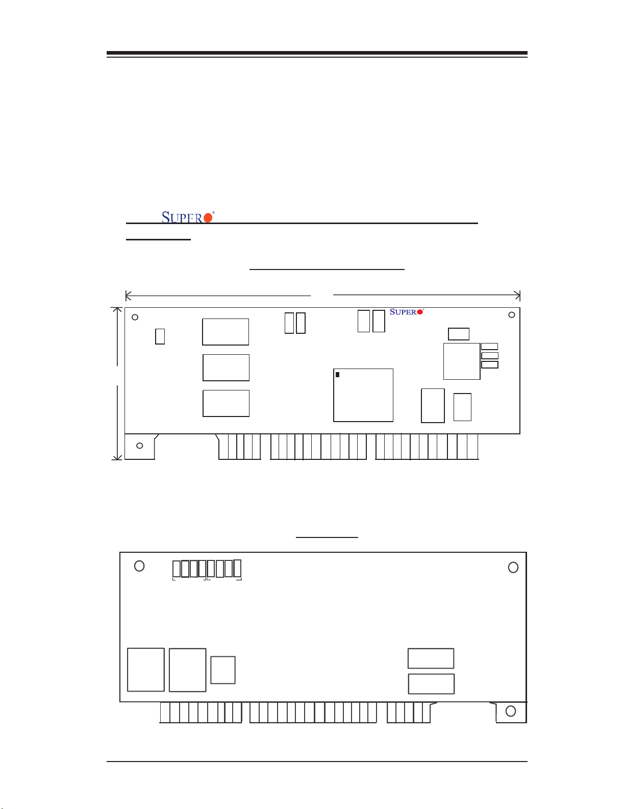
2.1 AOC-LPZCR1 Card Layout and Jumper Locations
2.1.1 AOC-LPZCR1 Card Layout and Jumper
Locations
2.5”
J4
Buzzer
Connector
Cache
Cache
Cache
Front view
DS14
DS13
5V LED
Rear view
(AOC-LPZCR1)
7.0”
J2
3V LED
J6
Flash
Firmware
I/O Processor
Act.
AOC-LPZCR1 Rev. 1.01
I2C
J1
CPLD
NVS
EPROM
RAM
Flash
SAS
J7
J5J3SATA2
SCSI
DS 8
Diag.LED
Flash EPROM
Flash EPROM
DS 7
DS 6
DS 4
DS 5
Diag.LED
SRAM
DS12
DS11
DS10
Cache
Cache
2-1
Page 8

AOC-LPZCR1/AOC-SOZCR1 User's Guide
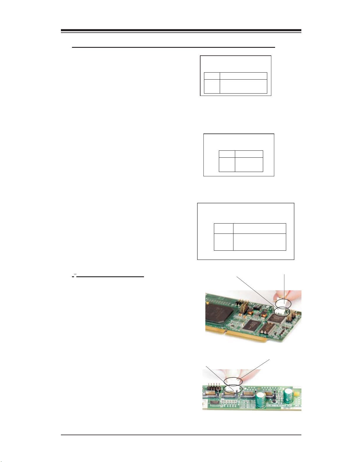
2.1.2 Jumper and Connector Descriptions (*AOC-LPZCR1)
Jumper Description
J2 Activity LED Connector (*See 2.1.3 for details)
J4 Buzzer Connector (*See 2.1.3 for details)
Connector Description
2
J1 Systerm Management Bus (I
connection on the next page.)
J3 SCSI Mode (On: Enable)
J5 Serial ATA Mode (SATA 2) Mode (On: Enable)
J6 Flash Firmware (On: Flashing Firmware)
J7 SAS Mode (On: Enable)
(DS10-12, DS4),(DS5-8)Diagnostic LED Indicators
C) (*See I2C cable
2-2
Page 9
Chapter 2: Technical Specifi cations and Installation
2.1.3 Connectors and LED Indicators (*AOC-LPZCR1)
Activity LED Indicator
Activity LED Indicator (J2), located
on the front side of the AOC-LPZCR1
card, indicate the activity status of the
AOC-LPZCR1 card. See the table on
the right for pin defi nitions.
Buzzer Connector
Buzzer Connector (J4), located on the
front side of the AOC-LPZCR1 card,
provides a connection for the onboard
buzzer. See the table on the right for
pin defi nitions.
SMB (I2C)
A System Management Bus header is
located at J1. Connect the I
2
C cable
here to utilize SMB on your add-on
card (*See below). See the table on
the right for pin defi nitions.
I2C Cable Connection
Acti vity LED
Pin Definitions (J2)
Pin# Pin Definitions
Pin1 -(Negtive) or Cathod
Pin2 +(Positive) or Anode
Buzzer Connector
Pin Definitions (J4)
Pin# Definitions
Pin1 +(Positive)
Pin2 -(Negtive)
SMB (I2C)
Pin Definitions (J1)
Pin
Number
1
2
3
3-Pin Connector (J1)
on the LPZCR1
Definition
Data
Ground
Clock
3-Pin Connector
on the cable
1. The I2C Cable has a 3-pin con-
nector on one end, and a 4-pin con-
nector on the other end.
2. Connect the 3-pin connector of
the cable to the 3-pin I
2
C Connec-
tor (J1) on the AOC-LPZCR card as
shown on the right.
3. Connect the 4-pin connector of
2
the cable to the 4-pin I
C Connector
4-Pin I
2
C Connector
on the Backplane
4-Pin Connector on
the cable
on the backplane as shown on the
right.
(*Note: Refer to the layout on Page 2-1 for the locations of the Connectors and
LED Indicators.
2-3
Page 10
AOC-LPZCR1/AOC-SOZCR1 User's Guide
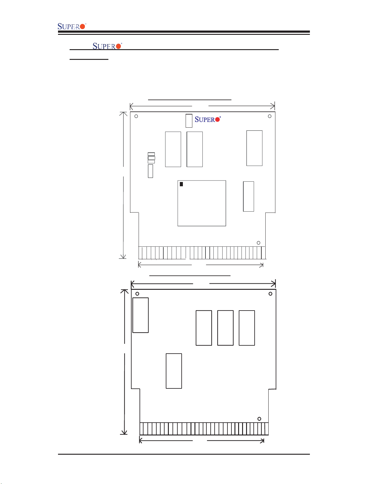
2.2.1 AOC-SOZCR1 Card Layout and Jumper
Locations
2.2 AOC-SOZCR1 Card Layout and Jumper Locations
Front view (AOC-SOZCR1)
3.19"
3.82"
Flash
J6
Firmw are
J 4
SAS
SATA 2
SCSI
J 3
J 2
C
2
I
J1
Cache
Pin 1
Cache
I/O Processor
2.66"
Rear view (AOC-SOZCR1)
3.19"
AOC-SO ZCR1
Flash EPROM
NVSRAM
U6
3.82"
Flash
Flash EPROM
2.66"
2-4
Cache
Cache
Cache
Page 11
Chapter 2: Technical Specifi cations and Installation
2.2.2 Connector and Header Descriptions (*AOC-SOZCR1)
Connector Description
J1 Systerm Management Bus (I
2
I
C cable connection.)
2
C) (*See Page 2-2 for
J2 SCSI Mode (On: Enable)
J3 Serial ATA (SATA2) Mode (On: Enable)
J4 SAS Mode (On: Enable)
J6 Flash Firmware (On: Flashing Firmware.)
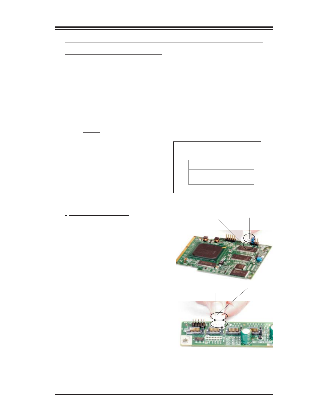
2.2.3 SMB Connector and Pin Defi nitions (*AOC-SOZCR1)
SMB (I2C)
A System Management Bus header is
located at J1. Connect the I2C cable
here to utilize SMB on your add-on
card (*See below). See the table on
the right for pin defi nitions.
I2C cable Connection
1. The I2C Cable has a 3-pin connec-
tor on one end, and a 4-pin connector
on the other end.
Number
3-Pin Connector (J1) on
SMB (I2C)
Pin Definitions (J1)
Pin
1
2
3
the SOZCR1
Definition
Ground
Data
Clock
3-PinConnector on
the cable
2. Connect the 3-pin connector of the
2
cable to the 3-pin I
C Connector (J1)
on the AOC-SOZCR1 card.
3. Connect the 4-pin connector of the
cable to the 4-pin I
2
C Connector on
4-Pin I
2
C Connector
on the Backplane
4-Pin Connector on
the cable
the backplane as shown on the right.
*Note 1: Refer to the layout on Page 2-4 for the locations of the Connectors and
LED Indicators.
2-5
Page 12
AOC-LPZCR1/AOC-SOZCR1 User's Guide
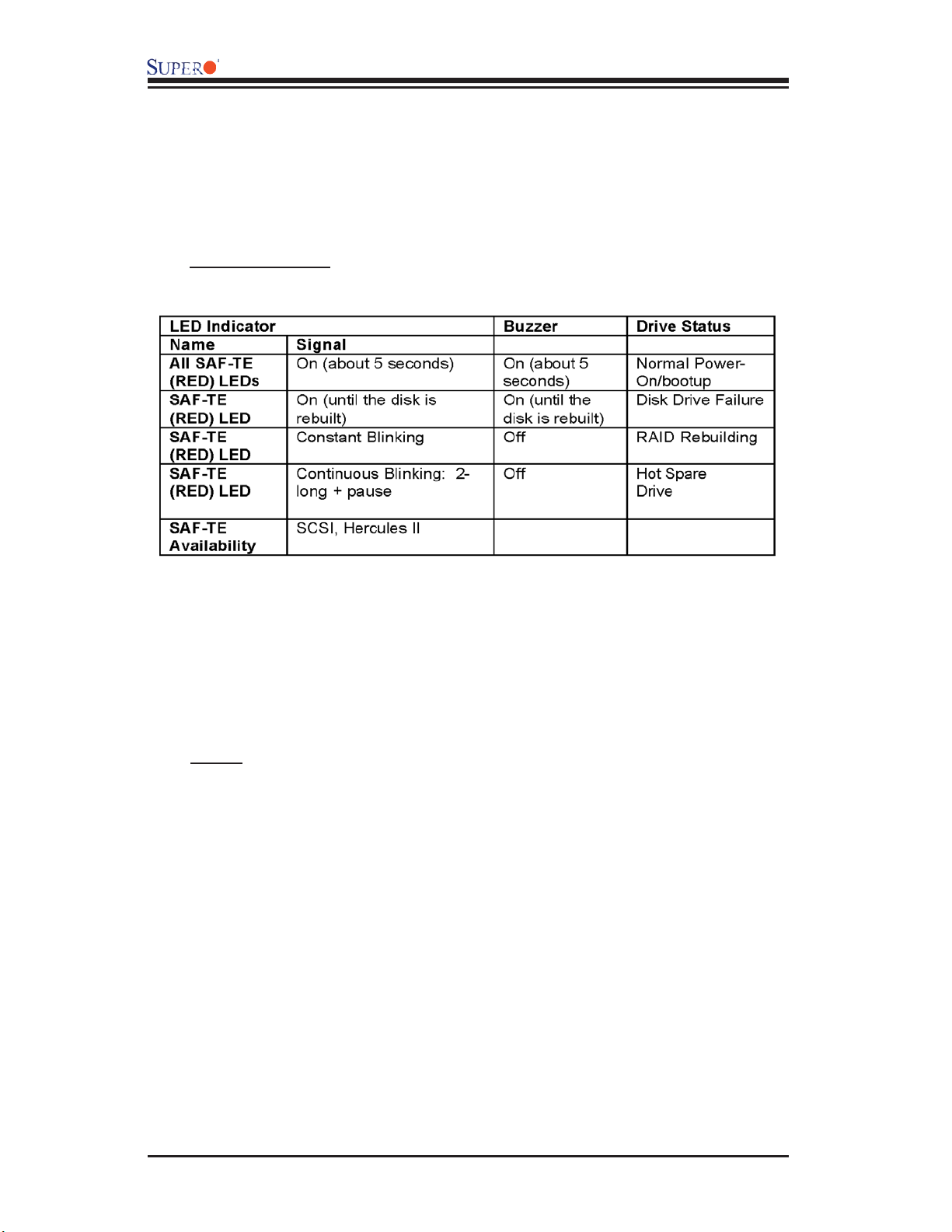
2.3 Intelligent Interface Management: SAF-TE
Both AOC-LPZCR1 and AOC-SOZCR1 models offer the feature of SAF-TE.
SAF-TE, (-SCSI Accessed Fault-Tolerant Enclosures Interface Specifi cation), is
a set of SCSI commands used to monitor hot-swap drives and inform the user
of the status of these drives through LED indicators. Refer to the table below for
details on SAF-TE LED Indicators.
(*See Note 1 below.)
(*Notes:
*Note 1: SAF-TE in the SATA Mode is available for OEM only. To support SAF-TE,
you will need to have a Supermicro's SATA backplane with the Q-Logic GEM-
424 Enclosure Management Controller pre-installed. By default, this function is
disabled.
*Note 2: SES-2 Enclosure Management in the SAS Mode will be provided when
available.)
2-6
Page 13

Chapter 2: Technical Specifi cations and Installation
2.4 Safety Guidelines
To avoid personal injury and property damage, please carefully
follow all the safety steps listed below when accessing your system
or handling the components:
ESD Safety Guidelines
Electric Static Discharge (ESD) can damage electronic com ponents. To prevent dam-
age to your system. it is important to handle it very carefully. The following measures
are generally suffi cient to protect your equipment from ESD.
• Use a grounded wrist strap designed to prevent static discharge.
• Touch a grounded metal object before removing a component from the antistatic
bag.
• Handle the RAID card by its edges only; do not touch its components, peripheral
chips, memory modules or gold contacts.
• When handling chips or modules, avoid touching their pins.
• Put the card and peripherals back into their antistatic bags when not in use.
General Safety Guidelines
• Always disconnect power cables before installing or removing any components
from the computer, including the RAID card.
• Use only the correct type of bracket for the chassis. Please use a full-height
bracket for a 1U, 3U, 4U, Tower, or a Pedestal system. Use a low-profi le bracket
for a 2U or some of the proprietary chassis. Make sure to secure the bracket
in the host system cabinet. (*Note: When used in a 1U system, the full-height
bracket is mounted into the riser card.)
• Disconnect the power cable before removing the Extended LED cable, data cable
2
or I
C cable from the riser card.
• Make sure that the riser card is securely seated in the PCI slot to prevent
damage to the system due to power shortage.
• Do not force a cable connector onto the controller or a drive.
2-7
Page 14

AOC-LPZCR1/AOC-SOZCR1 User's Guide
2.5 Installing the Controller Driver
2.5.1 Creating the Driver Floppy Disk:
A CD-ROM that contains the drivers for the Windows OS, the Linux Red Hat/SuSE
OS, and the Controller BIOS is included in the shipping package. Please locate
the CD-ROM before installing the driver. (*Note: this CD-ROM does not perform
Auto-boot or auto-play.)
For the Windows 32-bit Operating System:
• Copy all fi les from the folder: \Drive\Windows into a blank, formatted fl oppy disk.
(The folder is saved in the CDROM that came with your shipment.)
For the Red Hat/SuSE Operating System:
• Make the fl oppy disk by using the diskette image fi le at \Drive\Linux, which is
stored in the CD-ROM.
2.5.2 Adding the Driver into an Existing System
(*Note: An existing system is a system that has an operating system already
installed and the AOC-LPZCR1/AOC-SOZCR1 driver is being installed as a
Secondary Controller.)
For the Windows Operating System
a. Install the controller and make sure that its BIOS appears in POST.
b. Start the Windows OS. The Windows OS will launch the "Found New Hardware
Wizard" and search for the installer driver.
c. Insert the driver fl oppy disk that you've created into the computer, select the
fl oppy drive as the source, and press the <Enter> key.
d. Continue clicking <Next> until the driver is successfully installed.
e. Remove the driver disk from the FDD drive and restart the system to complete
the installation process.
For the Red Hat/SuSE Operating System
a. Start the Red Hat/SuSE OS.
b. Insert and mount the RPM driver Floppy or CD.
c. Type:"rpm -Uvh fi lename.rpm" at the prompt, and then, follow the instructions
given on the screen to install the driver. (*Note: fi lename=the fi le name of the
RPM driver that appears on your screen.)
d. Run fdisk, mkfs, and create a mount point for the new driver.
2-8
Page 15

Chapter 2: Technical Specifi cations and Installation
2.5.3 Installing the Driver into a New System
(*Note: A new system is a system that has no operating system installed yet,
and the AOC-LPZCR1/AOC-SOZCR1 driver installation is a part of the OS
installation.)
For the Windows Operating System
a. Install the controller and make sure that its BIOS appears in POST.
b. Insert the Windows Setup CD and boot from it.
c. When prompted at the bottom of the screen to install a third party driver, press
the <F6> key. (*Note: You have only 5 seconds to press <F6>. If you miss it,
you will need to restart the system and repeat this step again.)
d. Insert the driver disk into the computer, and wait until you are prompted to install
a driver. Press <S> to specify that the driver is included in an additional device-
-the fl oppy disk, and press <Enter>. (Refer to Page 2-7.)
e. When the Adaptec's driver disk--"Adaptec RAID Controller" is located, press
<Enter>.
f. Press <Enter> again to continue with the Windows OS installation.
For the Red Hat Operating System
a. Install the controller and make sure that its BIOS appears in POST.
b. Boot from the Linux CD.
c. Type: "linux dd" at the prompt, and follow the instructions given on the screen
to install the driver.
d. Remove the driver disk from the computer, and, then, restart the system to
complete the installation.
For the SuSE Operating System
a. Install the controller and make sure that its BIOS appears in POST.
b. Boot from the Linux CD.
c. While the kernel is booting, press <Alt>.
d. When prompted, insert the Driver Floppy Disk to the fl oppy drive and press
<Enter>.
e. Remove the driver disk from the computer, and, then, restart the system to
complete the installation.
2-9
Page 16

AOC-LPZCR1/AOC-SOZCR1 User's Guide
Notes
2-10
Page 17

Chapter 3: RAID Confi guration
Chapter 3
RAID Confi guration
After all the hardware has been installed in your system, you must fi rst confi gure
the Adaptec Embedded RAID Driver before you install the Windows operating
system. The necessary drivers are all included on the Supermicro bootable
CDs that came with your card.
(*Note: For the Adaptec RAID Confi guration Utility to function properly, you will
need to correctly setup the jumper settings of your add-on card fi rst before
using the Utility)
Confi guring Jumper Settings
To properly confi gure the jumper settings, please follow the table listed below
before using the Adaptec RAID Confi guration Utility. For more detailed informa-
tion on jumper settings and locations, please refer to Chapter 2.
SATA/SCSI Jumper Settings for the AOC-LPZCR1 (the Low-Profi le Card)
AOC-LPZCR1
Jumper/Function
To flash Firmware On
To enable SATA based on
Hercules II
To enable SCSI On
To Enable SAS On
Note1: For jumper locations, please refer to
Page 2-1
Note2: For jumper description, please refer to
Page 2-2
J6 J5 J3 J7
On
SATA/SCSI Jumper Settings for the AOC-SOZCR1 (the Socket Terminator
Card)
AOC-SOZCR1
Jumper/Function
To flash Firmware On
To enable SATA based on
Hercules II
To enable SCSI On
To Enable SAS On
Note1: For jumper locations, please refer to
Page 2-4
Note2: For jumper description, please refer to
Page 2-5
J6 J3 J2 J4
On
*Note 1: Refer to the layouts on Page 2-1 and Page 2-4 for jumper locations.
3-1
Page 18

AOC-LPZCR1/AOC-SOZCR1 Manual
Using Adaptec's RAID Confi guration Utility
The Adaptec RAID Confi guration Utility includes the following major compo-
nents:
1. Array Confi guration Utility: this utility allows the user to create and manage
arrays. You can also use this utility to initialize and scan disk drives.
2. SCSISelect Unity (or Serial/SATASelect): this utility allows the user to confi gure
the control settings for disk drives.
3. Disk Utility: this utility allows the user to format and verify disk drives.
To Use the Adaptec RAID Confi guration Utility
(*Note: the confi guration procedures listed below are applicable to
SAS, SATA and SCSI settings.)
To use the Adaptec RAID Confi guration Utility, please follow the steps listed
below:
1. Properly confi gure the jumper settings of your add-on card as indicated on
page 3-1.
2. Enable the RAID function in the system BIOS. (*Please refer to the User's
Guide that came with your system for system BIOS confi guration.)
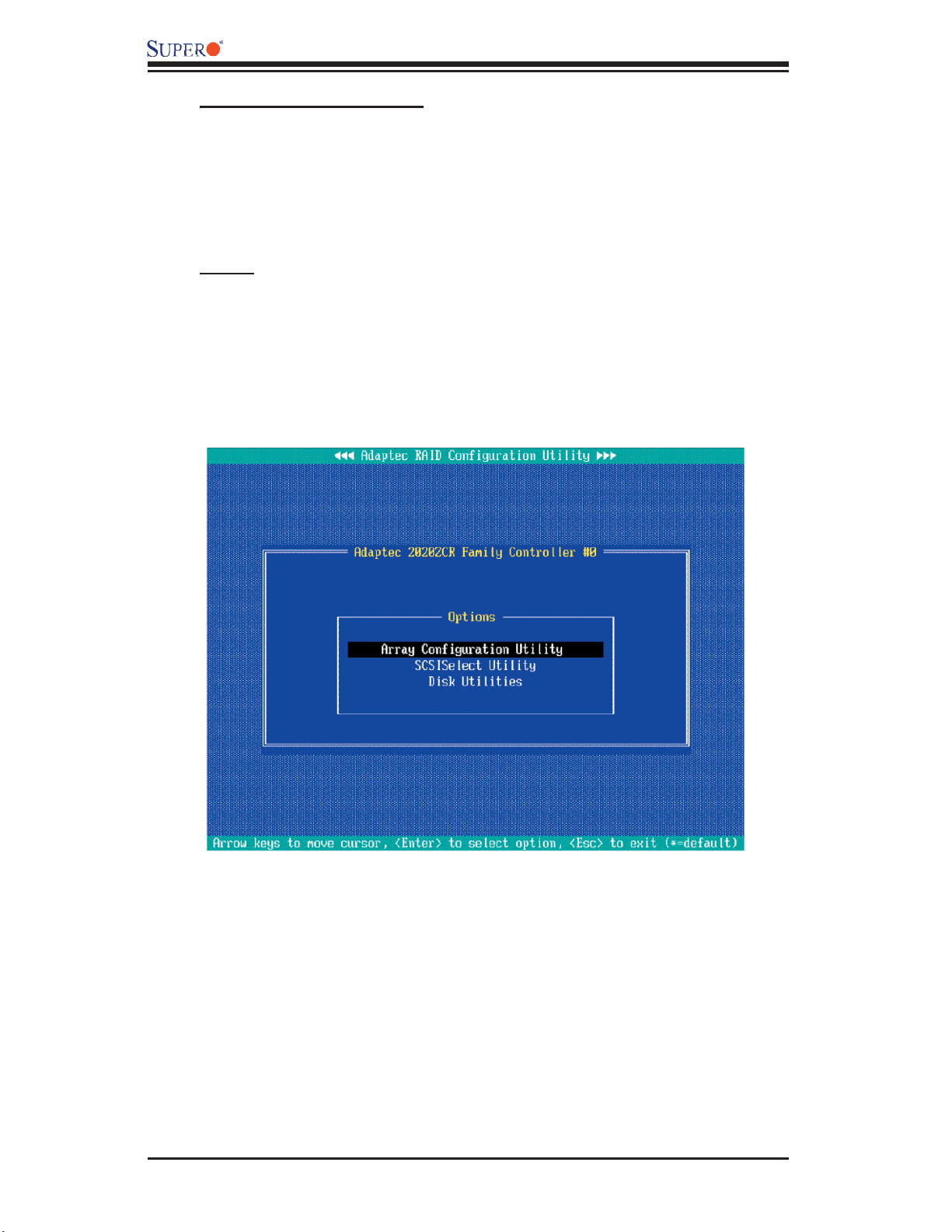
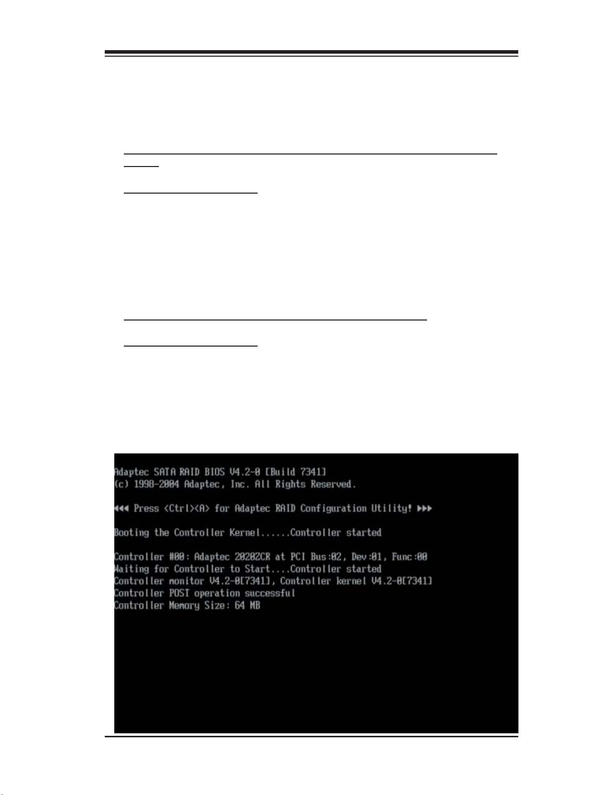
3. Turn on your computer. The BIOS screen as shown below will display during
system bootup:
3-2
Page 19

Chapter 3: RAID Confi guration
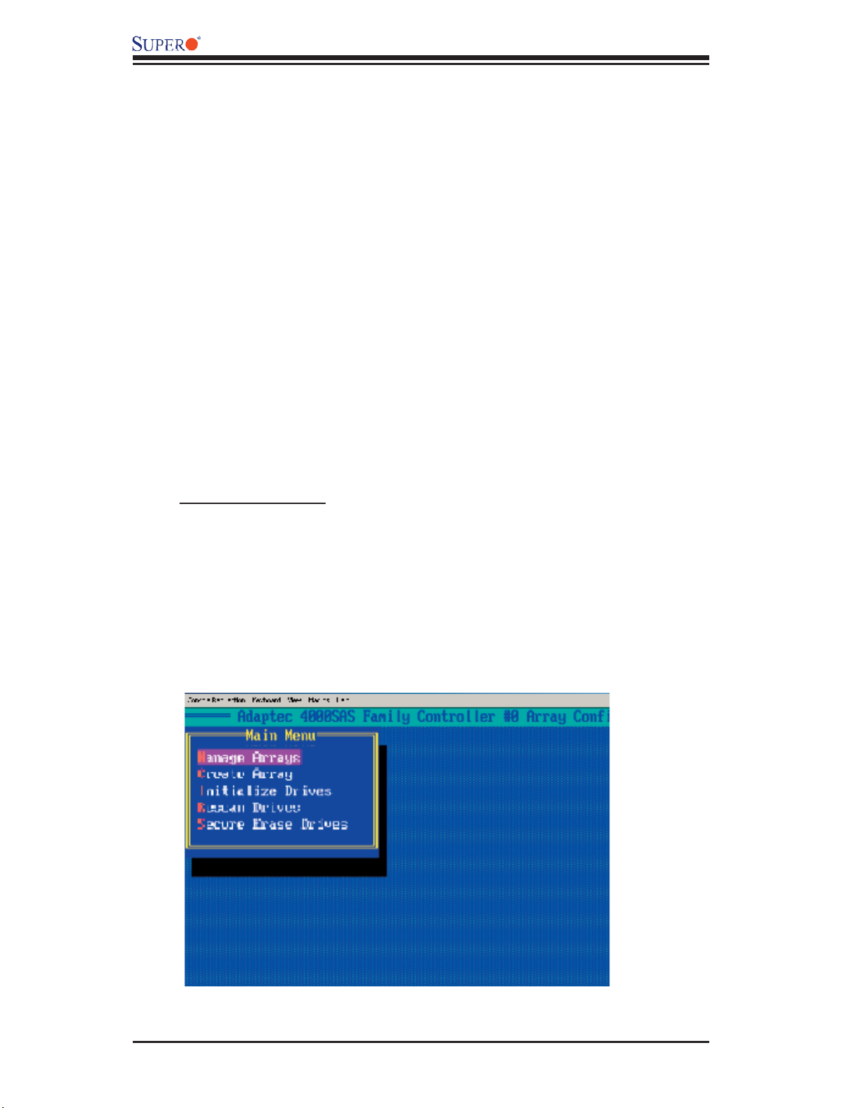
4. At the prompt, press the <Ctrl> and <A> keys simultaneously to enter the
Adaptec RAID Confi guration Utility. The RAID Confi guration Utility Main Menu
(as shown below) will appear:
Figure 3.1 The RAID Confi guration Utility Main Menu
3.1 Using the Array Confi guration Utility
The Array Confi guration Utility allows you to create, manage, delete arrays and
hot spare disk drives.
1. Select "Array Confi guration Utility" from the RAID Confi guration Main Menu
(Figure 3.1), and press <Enter>. The Array Confi guration Main Menu will display
as shown on the next page:
(*Note: You can use the arrow keys to highlight an item and then press the <En-
ter> key to select it. To return to the previous menu, press the <ESC> key.)
3-3
Page 20

AOC-LPZCR1/AOC-SOZCR1 Manual
Figure 3.2 The Array Confi guration Utility Main Menu
To Create Arrays
(*Note: Make sure that the disks you want to use for the arrays are connected
to your system and are initialized. A disk shown in the gray area is not initialized
and cannot be used for an array. Please refer to the section "Initializing Disk
Drives" for disk initialization.)
1. Turn on your computer. When prompted, press <Ctrl> and <A> to access the
Adaptec RAID Utility.
2. From the RAID Confi guration menu (Figure 3.1), select "Array Confi guration
Utility" and press <Enter>. The Array Confi guration Utility Main Menu (Figure
3.2) will display.
3. Select "Create Array" and hit <Enter> as shown above. The Create Array
submenu will display as shown on the next page:
3-4
Page 21

Chapter 3: RAID Confi guration
4. Use the arrow keys to highlight the channel(-the disk drive) you wish to create
a new array, and press <Insert>.
(*Note: To de-select any disk, highlight the disk and press <Del>.)
5. The disk drive that you've selected to create a new array will appear in the
"Selected Drives" dialogue box as shown below:
6. Once you've selected all the disk drives for new arrays, and all the drives
selected have appeared in the "Selected Drives" dialogue box, press <Enter>.
Then, a dialogue box showing array properties will display.
3-5
Page 22
AOC-LPZCR1/AOC-SOZCR1 Manual
To assign properties to the new array
7. In the "Array Properties" dialogue box, select the item you want to confi gure
and follow the instructions given on the screen to confi gure the settings for the
selected item.
(For the RAID type--you can select Volume, RAID 0 or RAID 1. To confi gure RAID
0 or RAID 1, you will need to have at least two drive disks. Select "Volume" to
confi gure a disk drive as an independent unit.)
8. Under "Arrays Label," you type in the name you wish to identify a disk drive,
and press <Enter>.
9. For RAID 0, select the desired stripe size. (You can select: 16, 32, or 64 KB
- default. Please do not change the default setting.)
10. You can also use the item "Create RAID via" to select the different methods
under RAID 0 and RAID 1.
11. Press <Esc> to return to the previous menu.
(*Note: Once the array is created and its properties are assigned, you cannot
change the properties by using Array Confi guration Utility.)
To Manage Arrays
The item "Manage Arrays" allows you to view, delete, set a boot array and
create hot spare drives.
1. Turn on your computer. When prompted, press <Ctrl> and <A> to access the
Adaptec RAID Utility.
2. From the RAID Confi guration menu (Figure 3.1), select "Array Confi guration
Utility" and press <Enter>. The Array Confi guration Utility Main Menu displays
as shown below:
3. From the main menu, select "Manage Arrays" and press <Enter> to access
the Manage Arrays submenu as shown below:
3-6
Page 23

Chapter 3: RAID Confi guration
To View the properties of Existing Arrays
4. A dialogue box showing a List of Arrays will display on the right. Select the
array you want to view as shown below:
5. Press <Enter>, and the "Array Properties" dialogue box will display, showing
detailed information. The physical disks associated with the array will also be
displayed as shown in the screen below:
6. Press <Esc> to return to the previous menu.
3-7
Page 24

AOC-LPZCR1/AOC-SOZCR1 Manual
Deleting Arrays
Warning: To prevent data loss, please back-up your data
before deleting arrays. You cannot restore a deleted array.
1. On the Array Confi guration main menu, select "Manage Arrays" and press
<Enter> to access the submenu as shown below:
2. From the "List of Arrays" dialogue box (on the right), select the array you
wish to delete and press <Del>.
3. The "Array Properties" dialogue box displays. In the "Properties" dialogue
box, select <Delete> and press <Enter>. The following warning message will
display:
Warning!! Deleting the array will erase all data from the Array. Do you
want to continue? (Yes/No):
4. Press <Yes> to delete the array, or press <No> to cancel the selection.
5. Press <Esc> to return to the previous menu.
3-8
Page 25

Chapter 3: RAID Confi guration
Setting a Bootable Array
1. From the Array Confi guration Main menu, select "Manage Arrays" and press
<Enter> to access the submenu as shown below:
2. From the List of Arrays dialogue box (on the right), highlight and select the
array you want to make as the fi rst bootable, and press <Ctrl> and <B> simul-
taneously.
3. The array selected as the 1st bootable array will appear on the top (-the
fi rst) of the List.
4. To re-assign the 1st boot array to another disk drive, select the array you wish
to confi gure, and press <Ctrl> and <B> simultaneously. The new 1st bootable
array will appear on the top of the list.
5. Press <Esc> to return to the previous menu.
3-9
Page 26

AOC-LPZCR1/AOC-SOZCR1 Manual
Adding a Hotspare Disk Drive
1. From the Array Confi guration Utility Main menu, select "Manage Arrays" and
press <Enter> to access the submenu as shown:
2. In the "List of Arrays" dialogue box (on the right), select the array you wish
to confi gure as a hot spare and press <Ctrl> and <S> simultaneously.
3. A "Hotspares" dialogue box displays, showing the drives that can be confi g-
ured as Hotspares.
4. Select the drive you wish to confi gure as a hotspare and press <Insert>.
The drive selected will appear in the Assigned Hotspares List. Then, press
<Enter>.
5. When prompted by a message, asking you if you want to confi rm the selection,
press <Yes> and <Enter> to confi gure the selected drive as a hotspare.
3-10
Page 27

Chapter 3: RAID Confi guration
Deleting a Hotspare Disk Drive
1. From the Array Confi guration Utility Main menu, select "Manage Arrays" and
press <Enter>.
2. In the "List of Arrays" dialogue box (on the right), select the Hotspare array
you wish to delete and press <Ctrl> and <S> simultaneously.
3. The "Hotspares" dialogue box displays, showing the drives that have been
confi gured as Hotspares.
4. From the Assigned Hotspare List, select the drive you want to remove and
press <Delete>.
5. The drive selected will appear in the Assigned Hotspares List. Then, press
<Enter>.
6. When prompted by a message, asking you if you to confi rm the selection,
press <Yes> to delete the hotspare drive.
3-11
Page 28
AOC-LPZCR1/AOC-SOZCR1 Manual
Initializing Disk Drives
Please be sure to initialize a disk drive before creating an array.
Caution: Initializing a disk will overwrite the partition table on the disk, making
any data on the disk inaccessible. If the drive is used in an array, you may not
be able to use the array again. You will also need to initialize a disk drive that is
attached to a controller before using the disk drive in an array.
Do not initialize a disk that is part of a boot array since disk initialization will
overwrite the data stored inside the disk. Refer to the item "Viewing Array Prop-
erties" to determine which disks are associated with a particular array.
To initialize Disk drives
1. Turn on your computer. When prompted, press <Ctrl> and <A> to access the
Adaptec RAID Utility.
2. From the RAID Confi guration menu (Figure 3.1), select "Array Confi gura-
tion Utility" and press <Enter>. The Array Confi guration Utility Main Menu (as
shown above) will display.
3-12
Page 29

Chapter 3: RAID Confi guration
3. From the Array Confi guration Utility Main Menu, select: "Initialize Drives" (as
shown above) and press <Enter>. The following screen will display:
4. From the list of drives (on the left), select the disk drive you wish to initialize
and press <Insert>. The drive will appear in the "Selected Drives" dialogue box
as show on the next page:
3-13
Page 30

AOC-LPZCR1/AOC-SOZCR1 Manual
5. Repeat the step above to select all the drives you wish to initialize. When all
the drives to be initialized are selected, press <Enter>, and a warning message
will display as shown below:
6. Make sure that you have selected the correct disk drives to initialize. If cor-
rect, type <Y> to proceed with the disk drive initialization. Type <N> to return
to the previous menu.
3-14
Page 31

Chapter 3: RAID Confi guration
Rebuilding Arrays
Note: If there is an interruption during array building or disk initialization, you
can rebuild an array. You can only confi gure RAID 1 for array rebuild. If a hard
disk fails and there is no hot spare array available, you will need to create a hot
spare drive fi rst before creating an array. (Refer to "Creating HotSpare Drives"
for more information.)
To Rebuild an array:
1. From the main menu, select Manage Arrays. From the list of arrays, select
the array you want to rebuild.
2. Press <Ctrl> and <R> simultaneously to rebuild an array.
To Rescan Disk drives
1. Power on your system. When prompted, press <Ctrl> and <A> simultane-
ously to access the Array Confi guration Utility.
2. When the Array Confi guration Utility Main Menu appears, select "Array Con-
fi guration Utility" and press <Enter>. The following screen will display:
3. From the Array Confi guration Main Menu appears, select "Rescan Drives" and
press <Enter>. The Array Confi guration Utility starts to rescan the selected disk
drives as shown in the screen on the next page:
3-15
Page 32

AOC-LPZCR1/AOC-SOZCR1 Manual
4. When fi nished, press <Esc> to return to the previous menu.
To Secure Erase Drives
1. Power on your system. When prompted, press <Ctrl> and <A> simultane-
ously to access the Array Confi guration Utility.
2. When the Array Confi guration Utility Main Menu appears, select "Array Con-
fi guration Utility" and press <Enter>. The following screen will display:
3. From the Main Menu appears, select "Secure Erase Drives" and press <En-
ter>. The following screen will appear:
3-16
Page 33

Chapter 3: RAID Confi guration
4. Use the up and down arrows to select the drive you wish to erase and press
<Insert>. The following screen displays:
5. Make sure that the drive selected is the correct one; then, press <Enter>.
6. The following message displays: "Warning! Secure Erase will erase all informa-
tion from the selected drive. Do you really want to continue?" Press <Y> to erase
the drive. Press <N> to abort the procedure and return to the main menu.
3-17
Page 34

AOC-LPZCR1/AOC-SOZCR1 Manual
3.2.1 Using Adaptec's SCSISelect Utility
(*Please refer to Page 3-1 for SCSI Jumper Confi guration before using
the SCSISelect Utility. Please refer to Section 3.2.2 for SATA, and Section
3.23 for SAS Utility Confi guration settings.)
1. Turn on your computer. When prompted, press <Ctrl> and <A> to access the
Adaptec RAID Utility.
2. From the RAID Confi guration menu, select "SCSISelect Utility" and press
<Enter> as shown below.
Using the Controller Confi guration Utility
3. To confi gure the RAID Controller or view Controller settings, select "Controller
Confi guration" from the SCSISelect sub-menu and press <Enter>. The Controller
Confi guration will be displayed as shown below:
4. Use the arrow keys to select the item to confi gure and press <Enter>. A dia-
logue box showing the controller interface defi nition appears.
5. Select the desired option in the dialogue box and press <Enter>.
6. Press <F6> to restore the default setting. Press <Esc> to return to the previ-
ous menu.
3-18
Page 35

Chapter 3: RAID Confi guration
Using the SCSI Confi guration Utility
1. From the Array Confi guration Utility Main Menu, select "SCSISelect Utility"
and press <Enter>.
2. From the SCSISelect Sub Menu, select SCSI Confi guration (as shown above)
and press <Enter> to access the submenu as shown below:
3. Use the arrow keys to select the item and press <Enter>. The status of the
selected channel displays as shown on the next page:
3-19
Page 36
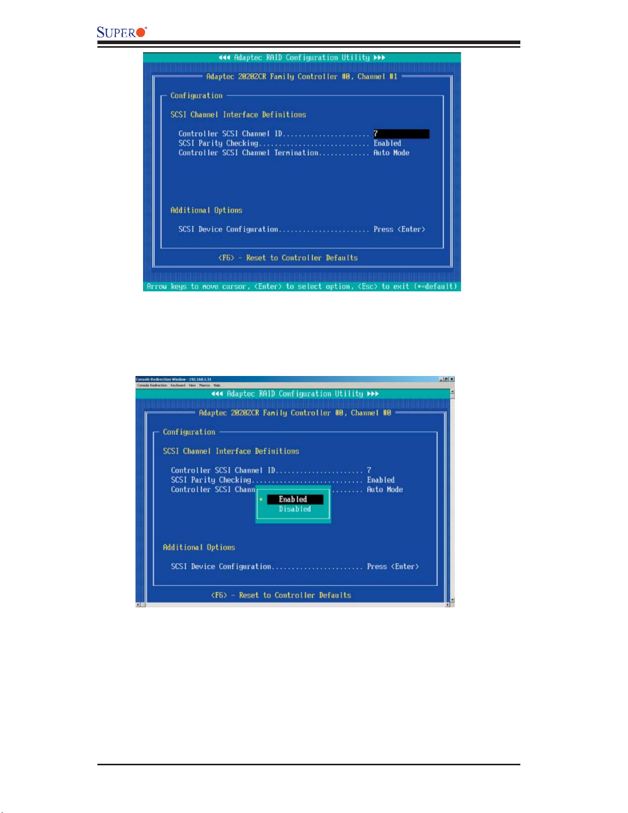
AOC-LPZCR1/AOC-SOZCR1 Manual
4. To confi gure an item, use the arrow keys to select the item and press <Enter>.
A dialogue box will appear, showing the status of the item.
5. Use the arrow keys to select the desired option and press <Enter> to change
the setting of an item. The following screen serves as an example:
6. To view the status of the SCSI drives or to confi gure SCSI drives, use the
arrow keys to select SCSI Device Confi guration (under "Additional Options"),
and press <Enter>. The current settings of the selected drive will be displayed
as shown on the next page:
3-20
Page 37

Chapter 3: RAID Confi guration
7. To change the setting of an item, use the arrow keys to select the item and
press <Enter> in the menu as shown above. (*Please refer to the table below
for detailed information.)
8. To restore the default setting, press <F6>. Press <Esc> to return to the
previous menu.
3-21
Page 38

AOC-LPZCR1/AOC-SOZCR1 Manual
3.2.2 Using Adaptec's SATASelect Utility
(*Please refer to Page 3-1 for SATA Jumper Confi guration before using the
SATASelect Utility. Please refer to Section 3..2.1 for SCSI and Section 3.2.3
for SAS Utility Confi guration settings.)
To Use the SATASelect Utility
1. Turn on your computer. When prompted, press <Ctrl> and <A> to access the
Adaptec RAID Confi guration Utility.
2. From the RAID Confi guration main menu (Figure 3.1), select "SATASelect
Utility" and press <Enter>.
Using the Controller Confi guration Utility
3. To confi gure the SATA RAID Controller or view the settings, select "Controller
Confi guration" from the sub-menu and press <Enter>.
5. To confi gure an item on the submenu, use the arrow keys to select the item
and press <Enter>. A dialogue box will appear.
5. Select the desired setting in the dialogue box and press <Enter> to select
the option.
6. Press <F6> to restore the default setting. Press <Esc> to return to the previ-
ous menu.
Using the SATA Confi guration Utility
1. Turn on your computer. When prompted, press <Ctrl> and <A> to access the
Adaptec RAID Confi guration Utility.
2. From the RAID Confi guration main menu (Figure 3.1), select "SATASelect
Utility" and press <Enter>.
Using the Controller Confi guration Utility
3. From the SATASelect Sub Menu, select SATA Confi guration and press <En-
ter>. The status of SATA Device Confi guration will display.
4. Use the arrow keys to select the item you wish to confi gure and press <Enter>.
A option dialogue box will display.
5. Use the arrow keys to select the desired setting and press <Enter>.
6. Press <F6> to load the default setting. To return to the previous menu, press
<Esc>.
(*Note: Refer to Section 3.2.4 on Page 3-24 for Physical Confi guration
Settings.)
3-22
Page 39

Chapter 3: RAID Confi guration
3.2.3 Using Adaptec's Serial Select Utility
(*Please refer to Page 3-1 for SAS Jumper Confi guration before using the
Serial_Select Utility. Please refer to Section 3..2.1 for SCSI and Section 3.2.3
for SAS Utility Confi guration settings.)
To Use the Serial_Select Utility
1. Turn on your computer. When prompted, press <Ctrl> and <A> to access the
Adaptec RAID Confi guration Utility.
2. From the RAID Confi guration main menu (Figure 3.1), select "Serial_Select
Utility" and press <Enter>.
Using the Controller Confi guration Utility
3. To confi gure the SAS RAID Controller or view the settings, select "Controller
Confi guration" from the sub-menu and press <Enter>.
5. To confi gure an item on the submenu, use the arrow keys to select the item
and press <Enter>. A dialogue box will appear.
5. Select the desired setting in the dialogue box and press <Enter> to select
the option.
6. Press <F6> to restore the default setting. Press <Esc> to return to the previ-
ous menu.
Using the Serial_Select Confi guration Utility to Confi gure SAS Settings
1. Turn on your computer. When prompted, press <Ctrl> and <A> to access the
Adaptec RAID Confi guration Utility.
2. From the RAID Confi guration main menu (Figure 3.1), select "Serial_Select
Utility" and press <Enter>.
Using the Controller Confi guration Utility
3. From the Serial_Select Sub Menu, select SAS Confi guration and press <En-
ter>. The status of SAS Device Confi guration will display.
4. Use the arrow keys to select the item you wish to confi gure and press <Enter>.
A option dialogue box will display.
5. Use the arrow keys to select the desired setting and press <Enter>.
6. Press <F6> to load the default setting. To return to the previous menu, press
<Esc>.
(*Note: Refer to Section 3.2.4 on Page 3-24 for Physical Confi guration
Settings.)
3-23
Page 40
AOC-LPZCR1/AOC-SOZCR1 Manual
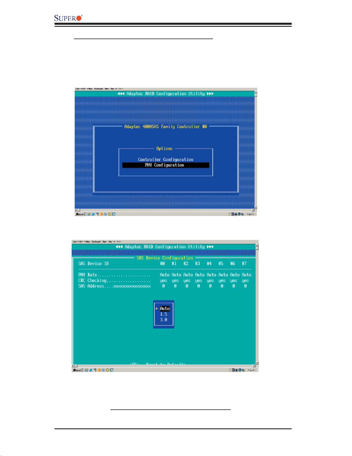
3.2.4 Using Physical Confi guration Utility
1. Power on your computer. When prompted, press the <Ctrl> and <A> keys
simultaneously to enter the RAID Confi guration Utility.
From the RAID Confi guration Main Menu, select "SerialSelect Utility" and
press <Enter> to access the Physical Confi guration submenu as shown below:
2. Select "Physical Confi guration" and press <Enter> to access SAS/SATA Device
Confi guration submenu.
3. Use the arrow keys to select an item. Press <Enter> to see the confi guration
settings of the item selected as shown in the screen above.
4. Use the up/down arrow keys to highlight the setting you wish to confi gure and
press <Enter>. (*Note: To load default settings, press <F6>.)
5. Press <Esc> to return to the previous menu and to exit the utility.
3-24
Page 41

Chapter 3: RAID Confi guration
3.3 Using Disk Utilities
The Disk Utilities enable you to format or to verify the integrity of your Hard
Drive Disks and to determine if there is any defect. (*Note: Formatting a disk
will overwrite data stored in the disk. Please backup your data before format-
ting a disk.)
3.3.1 To Use Disk Utilities (*for SCSI only)
(*Note: Please refer to Page 3-1 for SCSI Jumper confi guration before using
"Disk Utilities". Please refer to Section 3.3.2 for SAS and SATA Disk Utilities.)
1. Power on your computer. When prompted, press the <Ctrl> and <A> keys
simultaneously to enter the RAID Confi guration Utility. From the RAID Confi gu-
ration Main Menu, select "Disk Utilities" as shown below:
2. Select "Disk Utilities" and press <Enter>. The Disk Utilities Sub-Menu ap-
pears. From the submenu select the Channel (-the disk drive) you wish to
format or to scan.
3-25
Page 42

AOC-LPZCR1/AOC-SOZCR1 Manual
3. Once the disk drive is selected, press <Enter>. The Adaptec RAID Utility
starts re-scanning the selected drive, and a screen will display as below:
(*Note: Please refer to the following section for SAS and SATA
Disk Utilities.)
3-26
Page 43

Chapter 3: RAID Confi guration
3.3.2 To Use Disk Utilities (*for SATA and SAS only)
(*Note: Please refer to Page 3-1 for SATA and SAS Jumper Settings before using
"Disk Utilities". Please refer to the previous section for SCSI Disk Utilities.)
3.3.2.1 To Format a Disk Drive
1. Power on your computer. When prompted, press the <Ctrl> and <A> keys
simultaneously to enter the Adaptec RAID Confi guration Utility. From the RAID
Confi guration Main Menu, select "Disk Utilities" and press <Enter>. After disk
scan, the following screen displays:
2. When a dialogue box as shown above displays, prompting you to make a
selection, select the disk you wish to format and press <Enter>.
3. Then, select "Format Disk" from the displayed dialogue box and press <En-
ter>.
4. A warning message will display, warning you that the drive is about to be
formatted and all data in the drive will be erased.
5. Press <Yes> to continue with disk formatting. Press <No> to return to the
previous menu.
3-27
Page 44

AOC-LPZCR1/AOC-SOZCR1 Manual
3.3.2.2 To Verify Disk Media
1. Power on your computer. When prompted, press the <Ctrl> and <A> keys
simultaneously to access the Adaptec RAID Confi guration Utility. From the RAID
Confi guration Main Menu, select "Disk Utilities" and press <Enter>. After disk
scan, the following screen displays:
2. Whe a dialogue box as shown above displays, prompting you to make a
selection, select the disk you wish to verify and press <Enter>.
3. Then, select "Verify Disk Media" from the displayed dialogue box and press
<Enter>.
4. A dialogue box appears, showing you the status of the disk drive, and warn-
ing you that the disk drive selected will be scanned for media defects, and all
recoverable defects will be remapped.
5. Press <Yes> to continue with disk drive verifi cation. Press <No> to return to
the previous menu.
3.4 To Exit the Adaptec RAID Confi guration Utility
Once you have fi nished confi guring RAID array disk drives, press <Esc> to re-
turn to the Exit Menu. Select Yes and press <Enter> to exit the Adaptec RAID
Confi guration Utility.
3-28
Page 45
Chapter 4: Troubleshooting
Chapter 4
Troubleshooting
1. Problem: The AOC-LPZCR1/AOC-SOZCR1 BIOS does not show up in
POST.
Recommended Solutions:
• Make sure that the system has enough expansion ROM to initialize the card.
Remove other add-in cards if possible.
• Make sure that the card is properly and fully seated in the PCI green slot.
• Check if the motherboard's BIOS is updated. (You can download a updated BIOS
from our web site at: www.supermicro.com.)
2. Problem: I cannot see the card in the operating system.
Recommended Solutions:
• Make sure that the card is shown in POST. If the card is shown in POST, a
screen shown below will display. If it is not shown in POST, please fi nd out the
root cause of the problem by following the steps listed above.
• Make sure that the driver for the card is installed in the system.
4-1
Page 46

AOC-LPZCR1/AOC-SOZCR1 User's Guide
3. Problem: I cannot see the hard drives that are connected to the
controller.
Recommended Solutions:
• Make sure that there is power supply to the hard drives.
• Check the SAS, SATA or SCSI cable to make sure that there are no loose con-
nections between the card and the hard drives.
• If the hard drives are connected through a SAS, SATA or SCSI back panel, make
sure that there is power supply to the back panel, and there are no loose con-
nections between the back panel and the controller. Also make sure that the
hard drives are properly seated in the drive bay.
• If possible, swap the drives around to determine if the drive connections or the
controller is bad.
4. I cannot create software RAID in the operating system.
Recommended Solutions:
• Make sure that the operating system supports software RAID. If not sure, please
check with the software company that produces the OS.
• Make sure that more than one drives are seen by the OS.
Contacting Supermicro's Technical Support:
If you still have problems after trying out all the recommended solutions, please
contact our Tech. Support @ (408)503-8000 or visit our web site @ www.
supermicro.com/support/.
4-2
 Loading...