

Page 1
SUPER
SUPERSERVER
5017P-TLN4F
5017P-TF
®
USER’S MANUAL
1.0
Page 2

The information in this User’s Manual has been carefully reviewed and is believed to be accurate.
The vendor assumes no responsibility for any inaccuracies that may be contained in this document,
makes no commitment to update or to keep current the information in this manual, or to notify any
person or organization of the updates. Please Note: For the most up-to-date version of this
manual, please see our web site at www.supermicro.com.
Super Micro Computer, Inc. ("Supermicro") reserves the right to make changes to the product
described in this manual at any time and without notice. This product, including software and documentation, is the property of Supermicro and/or its licensors, and is supplied only under a license.
Any use or reproduction of this product is not allowed, except as expressly permitted by the terms
of said license.
IN NO EVENT WILL SUPERMICRO BE LIABLE FOR DIRECT, INDIRECT, SPECIAL, INCIDENTAL,
SPECULATIVE OR CONSEQUENTIAL DAMAGES ARISING FROM THE USE OR INABILITY TO
USE THIS PRODUCT OR DOCUMENTATION, EVEN IF ADVISED OF THE POSSIBILITY OF
SUCH DAMAGES. IN PARTICULAR, SUPERMICRO SHALL NOT HAVE LIABILITY FOR ANY
HARDWARE, SOFTWARE, OR DATA STORED OR USED WITH THE PRODUCT, INCLUDING THE
COSTS OF REPAIRING, REPLACING, INTEGRATING, INSTALLING OR RECOVERING SUCH
HARDWARE, SOFTWARE, OR DATA.
Any disputes arising between manufacturer and customer shall be governed by the laws of Santa
Clara County in the State of California, USA. The State of California, County of Santa Clara shall
be the exclusive venue for the resolution of any such disputes. Super Micro's total liability for all
claims will not exceed the price paid for the hardware product.
FCC Statement: This equipment has been tested and found to comply with the limits for a Class A
digital device pursuant to Part 15 of the FCC Rules. These limits are designed to provide reasonable
protection against harmful interference when the equipment is operated in a commercial environment. This equipment generates, uses, and can radiate radio frequency energy and, if not installed
and used in accordance with the manufacturer’s instruction manual, may cause harmful interference
with radio communications. Operation of this equipment in a residential area is likely to cause harmful
interference, in which case you will be required to correct the interference at your own expense.
California Best Management Practices Regulations for Perchlorate Materials: This Perchlorate warning applies only to products containing CR (Manganese Dioxide) Lithium coin cells. “Perchlorate
Material-special handling may apply. See www.dtsc.ca.gov/hazardouswaste/perchlorate”
WARNING: Handling of lead solder materials used in this
product may expose you to lead, a chemical known to the
State of California to cause birth defects and other reproductive harm.
Manual Revision 1.0
Release Date: July 19, 2012
Unless you request and receive written permission from Super Micro Computer, Inc., you may not
copy any part of this document.
Information in this document is subject to change without notice. Other products and companies
referred to herein are trademarks or registered trademarks of their respective companies or mark
holders.
Copyright © 2012 by Super Micro Computer, Inc.
All rights reserved.
Printed in the United States of America
Page 3

Preface
About This Manual
This manual is written for professional system integrators and PC technicians. It pro-
vides information for the installation and use of the SuperServer 5017P-TLN4F/TF.
Installation and maintainance should be performed by experienced technicians only.
The SuperServer 5017P-TLN4F/TF is a high-end server based on the SC504-
203B rackmountable chassis and the X9SPV-LN4F/F-3610ME single processor
serverboard.
Manual Organization
Chapter 1: Introduction
The rst chapter provides a checklist of the main components included with the
server system and describes the main features of the X9SPV-LN4F/F-3610ME
serverboard and the SC504-203B chassis.
Chapter 2: Server Installation
Preface
This chapter describes the steps necessary to install the SuperServer 5017P-TL-
N4F/TF into a rack and check out the server conguration prior to powering up the
system. If your server was ordered without processor and memory components, this
chapter will refer you to the appropriate sections of the manual for their installation.
Chapter 3: System Interface
Refer here for details on the system interface, which includes the functions and
information provided by the control panel on the chassis as well as other LEDs
located throughout the system.
Chapter 4: System Safety
You should thoroughly familiarize yourself with this chapter for a general overview
of safety precautions that should be followed when installing and servicing the
SuperServer 5017P-TLN4F/TF.
iii
Page 4

SUPERSERVER 5017P-TLN4F/TF User's Manual
Chapter 5: Advanced Serverboard Setup
Chapter 5 provides detailed information on the X9SPV-LN4F/F-3610ME serverboard,
including the locations and functions of connections, headers and jumpers. Refer
to this chapter when adding or removing processors or main memory and when
reconguring the serverboard.
Chapter 6: Advanced Chassis Setup
Refer to Chapter 6 for detailed information on the SC504-203B server chassis.
You should follow the procedures given in this chapter when installing, removing
or reconguring SAS/SATA or peripheral drives and when replacing system power
supply units and cooling fans.
Chapter 7: BIOS
The BIOS chapter includes an introduction to BIOS and provides detailed informa-
tion on running the CMOS Setup Utility.
Appendix A: BIOS Error Beep Codes
Appendix B: System Specications
iv
Page 5

Notes
Preface
v
Page 6

SUPERSERVER 5017P-TLN4F/TF User's Manual
Table of Contents
Chapter 1 Introduction
1-1 Overview ......................................................................................................... 1-1
1-2 Motherboard Features ..................................................................................... 1-2
Processors ...................................................................................................... 1-2
Memory ........................................................................................................... 1-2
Serial ATA ........................................................................................................ 1-2
PCI Expansion Slots ....................................................................................... 1-2
Rear I/O Ports ................................................................................................. 1-2
1-3 Server Chassis Features ................................................................................ 1-3
System Power ................................................................................................. 1-3
Hard Drive Subsystem .................................................................................... 1-3
Front Control Panel ......................................................................................... 1-3
1-4 Contacting Supermicro .................................................................................... 1-5
Chapter 2 Server Installation
2-1 Overview ......................................................................................................... 2-1
2-2 Unpacking the System .................................................................................... 2-1
2-3 Preparing for Setup ......................................................................................... 2-1
Choosing a Setup Location ............................................................................. 2-1
Rack Precautions ............................................................................................ 2-2
Server Precautions .......................................................................................... 2-2
Rack Mounting Considerations ....................................................................... 2-3
Ambient Operating Temperature ................................................................ 2-3
Reduced Airow ......................................................................................... 2-3
Mechanical Loading ................................................................................... 2-3
Circuit Overloading ..................................................................................... 2-3
Reliable Ground ......................................................................................... 2-3
2-4 Installing the System into a Rack ................................................................... 2-4
Installing the Chassis into a Standard Rack ................................................... 2-4
Telco Rack ....................................................................................................... 2-5
Installing the Chassis into a Telco Rack ......................................................... 2-5
Chapter 3 System Interface
3-1 Overview ......................................................................................................... 3-1
3-2 Control Panel Buttons ..................................................................................... 3-1
Reset ............................................................................................................... 3-1
Power .............................................................................................................. 3-1
3-3 Control Panel LEDs ........................................................................................ 3-2
vi
Page 7

Table of Contents
Power Fail ....................................................................................................... 3-2
NIC1 ................................................................................................................ 3-2
NIC2 ................................................................................................................ 3-2
HDD ................................................................................................................. 3-3
Power .............................................................................................................. 3-3
3-4 Drive Carrier LEDs .......................................................................................... 3-3
Chapter 4 System Safety
4-1 Electrical Safety Precautions .......................................................................... 4-1
4-2 General Safety Precautions ............................................................................ 4-2
4-3 ESD Precautions ............................................................................................. 4-3
4-4 Operating Precautions .................................................................................... 4-4
Chapter 5 Advanced Motherboard Setup
5-1 Handling the Motherboard .............................................................................. 5-1
Precautions ..................................................................................................... 5-1
Unpacking ....................................................................................................... 5-1
5-2 Connecting Cables .......................................................................................... 5-2
Connecting Data Cables ................................................................................. 5-2
Connecting Power Cables .............................................................................. 5-2
Connecting the Control Panel ......................................................................... 5-2
5-3 Rear I/O Ports ................................................................................................. 5-3
5-4 Onboard Processor and Heatsink ................................................................... 5-4
5-5 Installing Memory ............................................................................................ 5-4
How to Install SO DIMMs ............................................................................... 5-4
Memory Support .............................................................................................. 5-4
5-6 Adding PCI Add-On Cards .............................................................................. 5-4
The SO DIMM Socket ..................................................................................... 5-5
5-7 Motherboard Details ........................................................................................ 5-6
X9SPV-LN4F/F-3610ME Quick Reference ..................................................... 5-7
5-8 Connector Denitions ..................................................................................... 5-8
5-9 Jumper Settings ............................................................................................ 5-14
5-10 Onboard Indicators ........................................................................................ 5-16
5-11 SATA and SAS Ports .....................................................................................5-17
5-12 Installing Software ......................................................................................... 5-18
SuperDoctor III .............................................................................................. 5-19
Chapter 6 Advanced Chassis Setup
6-1 Static-Sensitive Devices .................................................................................. 6-1
Precautions ..................................................................................................... 6-1
Unpacking ....................................................................................................... 6-1
vii
Page 8

SUPERSERVER 5017P-TLN4F/TF User's Manual
6-2 Control Panel .................................................................................................. 6-2
6-3 Removing the Chassis Cover ......................................................................... 6-3
6-4 System Fans ................................................................................................... 6-4
6-5 Installing Hard Drives ...................................................................................... 6-4
6-6 Installing an Expansion Card .......................................................................... 6-6
6-7 Power Supply .................................................................................................. 6-8
Replacing the Power Supply ........................................................................... 6-8
Chapter 7 BIOS
7-1 Introduction ...................................................................................................... 7-1
Starting BIOS Setup Utility .............................................................................. 7-1
How To Change the Conguration Data ......................................................... 7-1
How to Start the Setup Utility ......................................................................... 7-2
7-2 Main Setup ...................................................................................................... 7-2
7-3 Advanced Setup Congurations...................................................................... 7-4
NIC Conguration ....................................................................................... 7-23
7-4 Event Logs .................................................................................................... 7-23
7-5 IPMI Settings ................................................................................................. 7-25
7-6 Boot ............................................................................................................... 7-27
7-7 Security Settings ........................................................................................... 7-28
7-8 Exit ................................................................................................................ 7-29
Appendix A POST Error Beep Codes
Appendix B System Specications
viii
Page 9

Chapter 1: Introduction
Chapter 1
Introduction
1-1 Overview
The SuperServer 5017P-TLN4F/TF is a mini server comprised of two main sub-
systems: the SC504-203B 1U chassis and the X9SPV-LN4F/F-3610ME single
processor motherboard. Please refer to our web site for information on operating
systems that have been certied for use with the system (www.supermicro.com).
In addition to the motherboard and chassis, various hardware components have
been included with the 5017P-TLN4F/TF, as listed below:
•One riser card bracket (MCP-120-00063-0N)
•One riser card (RSC-RR1U-E16)
•One CD containing drivers and utilities
•One rackmount kit (MCP-290-00053-0N)
•SuperServer 5017P-TLN4F/TF User's Manual
1-1
Page 10

SUPERSERVER 5017P-TLN4F/TF User's Manual
1-2 Motherboard Features
The SuperServer 5017P-TLN4F/TF is built around the X9SPV-LN4F/F-3610ME, a
single processor motherboard based on the Intel QM77 chipset and designed to
provide maximum performance. Below are the main features of the X9SPV-LN4F/F-
3610ME. (See Figure 1-1 for a block diagram of the chipset).
Processors
The X9SPV-LN4F/F-3610ME supports a single Intel® Core i7 Mobile ECC pro-
cessor. Please refer to the motherboard description pages on our web site for a
complete listing of supported processors (www.supermicro.com).
Memory
The X9SPV-LN4F/F-3610ME has two SO-DIMM slots that can support up to 16 GB
of unbuffered DDR3-1333/1066/800 memory. See Chapter 5 for details.
Serial ATA
A SATA controller is also integrated into the chipset to provide two SATA 3.0 (6/
Gbps) and four SATA 2.0 (3 Gbps) ports. That SATA 3.0 ports are RAID 0 and 1
supported and the SATA 2.0 ports are RAID 0, 1, 5 and 10 supported. The SATA
drives are hot-swappable units.
PCI Expansion Slots
The X9SPV-LN4F/F-3610ME has one PCI-E 3.0 x16 slot.
Rear I/O Ports
The color-coded I/O ports include one COM port, a combination mouse/keyboard
port, a VGA port, two USB 2.0 ports, four 1 Gb Ethernet ports and a dedicated IPMI
LAN port. In addition, the X9SPV-LN4F includes two extra Gb LAN ports.
1-2
Page 11

Chapter 1: Introduction
1-3 Server Chassis Features
The SC504-203B is an ATX form factor chassis designed to be used in a 1U rack-
mount conguration. The following is a general outline of the main features of the
SC504-203B server chassis.
System Power
The SC504-203B features a single 200W power supply. Power must be removed
from the system and the AC power cord removed when replacing. See Chapter 6
for details.
Hard Drive Subsystem
Either two 3.5" internal drive or four 2.5" internal drives (with a 2.5" HDD bracket)
are suppor ted by the system. These are not hot-swap drives.
Front Control Panel
The control panel on the SC504-203B provides you with system monitoring and
control. LEDs indicate system power, HDD activity, network activity, system infor-
mation and power supply failure. A main power button and a system reset button
are also included.
1-3
Page 12
SUPERSERVER 5017P-TLN4F/TF User's Manual
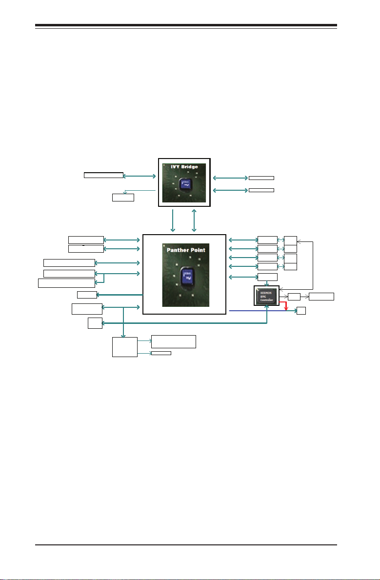
Figure 1-1. Intel QM77 Chipset:
System Block Diagram
Note: This is a general block diagram. Please see Chapter 5 for details.
2x SATA PORTS
4x SATA PORTS
4x USB3.0 by Header
x2 TWO PORT HEADERs
2X Stacked 2 port rear I/O
FLASH
SPI 64Mb
Debug Header
PCIe x16 SLOT
SPI
TPM
IMVP 7
SATA 6Gb/s
SATA 3Gb/s
USB3.0
USB2.0
LPC
NCT6776F
LPC I/O
PCIe3.0_x16
8.0GT/s
SVID
SATA[1:0]
SATA[5:2]
USB[3:0]
USB[13:4]
SPI
LPC
COM1 (rear I/O)
COM2 (internal header)
P/S2
DDR3 (CHA)
1333/1067 MHz
DDR3 (CHB)
1333/1067 MHz
FDI X4
5.0GT/s
DMI 2.0 x4
PCIE[0]
PCIE[1]
PCIE[2]
PCIE[3]
PCIE[4]
RGB
ECC-SODIMM1
ECC-SODIMM2
PCIe1.0_x1
2.5GT/s
PCIe1.0_x1
2.5GT/s
PCIe1.0_x1
2.5GT/s
PCIe1.0_x1
2.5GT/s
PCIe1.0_x1 IDT
2.5GT/s
for non-IPMI SKU
GLAN1
82574L
GLAN2
82574L
GLAN3
82574L
GLAN4
82574L
PEB383
PCI
RJ45
RJ45
RJ45
RJ45
NCSI
PHY Dedicated Lan
for IPMI SKU
VGA
1-4
Page 13

1-4 Contacting Supermicro
Headquarters
Address: Super Micro Computer, Inc.
980 Rock Ave.
San Jose, CA 95131 U.S.A.
Tel: +1 (408) 503-8000
Fax: +1 (408) 503-8008
Email: marketing@supermicro.com (General Information)
support@supermicro.com (Technical Support)
Web Site: www.supermicro.com
Europe
Address: Super Micro Computer B.V.
Het Sterrenbeeld 28, 5215 ML
's-Hertogenbosch, The Netherlands
Tel: +31 (0) 73-6400390
Fax: +31 (0) 73-6416525
Email: sales@supermicro.nl (General Information)
support@supermicro.nl (Technical Support)
rma@supermicro.nl (Customer Support)
Chapter 1: Introduction
Asia-Pacic
Address: Super Micro Computer, Inc.
4F, No. 232-1, Liancheng Rd.
Chung-Ho Dist., New Taipei City 235
Taiwan
Tel: +886-(2) 8226-3990
Fax: +886-(2) 8226-3991
Web Site: www.supermicro.com.tw
Technical Support:
Email: support@supermicro.com.tw
Tel: 886-2-8228-1366, ext.132 or 139
1-5
Page 14

SUPERSERVER 5017P-TLN4F/TF User's Manual
Notes
1-6
Page 15

Chapter 2: Server Installation
Chapter 2
Server Installation
2-1 Overview
This chapter provides a quick setup checklist to get your SuperServer 5017P-
TLN4F/TF up and running. Following these steps in the order given should enable
you to have the system operational within a minimum amount of time. This quick
setup assumes that your system has come to you with the processors and memory
preinstalled. If your system is not already fully integrated with a serverboard, pro-
cessors, system memory etc., please turn to the chapter or section noted in each
step for details on installing specic components.
2-2 Unpacking the System
You should inspect the box the SuperServer 5017P-TLN4F/TF was shipped in and
note if it was damaged in any way. If the server itself shows damage you should
le a damage claim with the carrier who delivered it.
Decide on a suitable location for the rack unit that will hold the SuperServer 5017P-
TLN4F/TF. It should be situated in a clean, dust-free area that is well ventilated.
Avoid areas where heat, electrical noise and electromagnetic elds are generated.
You will also need it placed near a grounded power outlet. Read the Rack and
Server Precautions in the next section.
2-3 Preparing for Setup
The box the SuperServer 5017P-TLN4F/TF was shipped in should include two
sets of rail assemblies, two rail mounting brackets and the mounting screws you
will need to install the system into the rack. Follow the steps in the order given to
complete the installation process in a minimum amount of time. Please read this
section in its entirety before you begin the installation procedure outlined in the
sections that follow.
Choosing a Setup Location
•Leave enough clearance in front of the rack to enable you to open the front door
completely (~25 inches) and approximately 30 inches of clearance in the back
of the rack to allow for sufcient airow and ease in servicing.
2-1
Page 16

SUPERSERVER 5017P-TLN4F/TF User's Manual
•This product is for installation only in a Restricted Access Location (dedicated
equipment rooms, service closets and the like).
•This product is not suitable for use with visual display work place devices
acccording to §2 of the the German Ordinance for Work with Visual Display
Units.
Warnings and Precautions!
Rack Precautions
•Ensure that the leveling jacks on the bottom of the rack are fully extended to
the oor with the full weight of the rack resting on them.
•In single rack installation, stabilizers should be attached to the rack. In multiple
rack installations, the racks should be coupled together.
•Always make sure the rack is stable before extending a component from the
rack.
•You should extend only one component at a time - extending two or more si-
multaneously may cause the rack to become unstable.
Server Precautions
•Review the electrical and general safety precautions in Chapter 4.
•Determine the placement of each component in the rack before you install the
rails.
•Install the heaviest server components on the bottom of the rack rst, and then
work up.
•Use a regulating uninterruptible power supply (UPS) to protect the server from
power surges, voltage spikes and to keep your system operating in case of a
power failure.
•Allow any hot plug drives and power supply modules to cool before touching
them.
•Always keep the rack's front door and all panels and components on the servers
closed when not servicing to maintain proper cooling.
2-2
Page 17

Chapter 2: Server Installation
Rack Mounting Considerations
Ambient Operating Temperature
If installed in a closed or multi-unit rack assembly, the ambient operating tempera-
ture of the rack environment may be greater than the ambient temperature of the
room. Therefore, consideration should be given to installing the equipment in an
environment compatible with the manufacturer’s maximum rated ambient tempera-
ture (Tmra).
Reduced Airow
Equipment should be mounted into a rack so that the amount of airow required
for safe operation is not compromised.
Mechanical Loading
Equipment should be mounted into a rack so that a hazardous condition does not
arise due to uneven mechanical loading.
Circuit Overloading
Consideration should be given to the connection of the equipment to the power
supply circuitry and the effect that any possible overloading of circuits might have
on overcurrent protection and power supply wiring. Appropriate consideration of
equipment nameplate ratings should be used when addressing this concern.
Reliable Ground
A reliable ground must be maintained at all times. To ensure this, the rack itself
should be grounded. Particular attention should be given to power supply connec-
tions other than the direct connections to the branch circuit (i.e. the use of power
strips, etc.).
2-3
Page 18
SUPERSERVER 5017P-TLN4F/TF User's Manual
2-4 Installing the System into a Rack
This section provides information on installing the SC504 chassis into a rack unit.
There are a variety of rack units on the market, which may mean the assembly
procedure will differ slightly. You should also refer to the installation instructions that
came with the rack unit you are using.
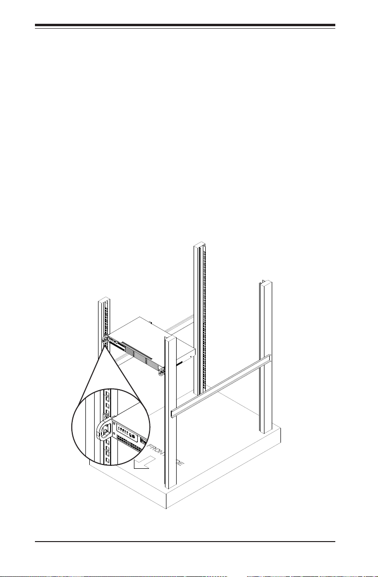
Installing the Chassis into a Standard Rack
1. Conrm that chassis includes the four mounting screws required to mount the
chassis into a rack
2. Align the thru holes of the chassis with the thru holes of the rack.
3. Insert the mounting screws into the thru holes in the front of the chassis and
through the thru holes in the rack and secure.
Figure 2-1. Installing the Chassis into a Rack
2-4
Page 19
Chapter 2: Server Installation
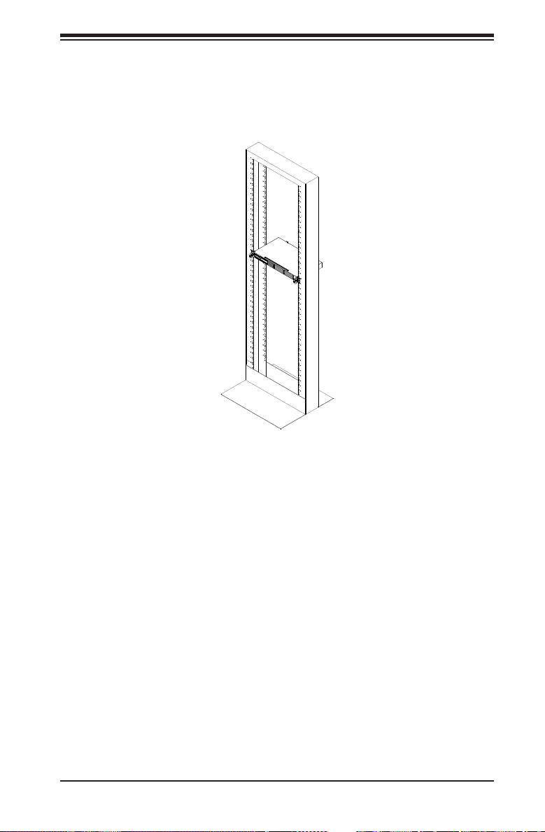
Telco Rack
The SC504 supports Telco Rack installation. The SC504 chassis' compact design
allows the it to be installed into a Telco rack without the use of rails.
Figure 2-2. Installing the Chassis into a Telco Rack
Installing the Chassis into a Telco Rack
1. To install the chassis into a Telco style two-post rack, use two L-shaped
brackets on either side of the chassis (four total).
2. First, determine how far follow the server will extend out the front of the rack.
Larger chassis should be positioned to balance the weight between front and
back.
3. If a bezel is included on your chassis, remove it. Then attach the two front
brackets to each side of the chassis, then the two rear brackets positioned
with just enough space to accommodate the width of the Telco rack.
4. Finish by sliding the chassis into the rack and tightening the brackets to the
rack.
Note: the gures are for illustrative purposes only. Always install chassis starting
from the bottom of the rack and working up.
2-5
Page 20

SUPERSERVER 5017P-TLN4F/TF User's Manual
Notes
2-6
Page 21
Chapter 3: System Interface
Chapter 3
System Interface
3-1 Overview
There are several LEDs on the control panel as well as others on the drive carriers
to keep you constantly informed of the overall status of the system and the activ-
ity and health of specic components. There are also two buttons on the chassis
control panel.
3-2 Control Panel Buttons
There are two buttons located on the front of the chassis: a reset button and a
power on/off button.
Reset
Use the reset button to reboot the system.
Power
This is the main power button, which is used to apply or turn off the main system
power. Turning off system power with this button removes the main power but keeps
standby power supplied to the system.
3-1
Page 22
SUPERSERVER 5017P-TLN4F/TF User's Manual
3-3 Control Panel LEDs
The control panel located on the front of the chassis has ve LEDs. These LEDs
provide you with critical information related to different parts of the system. This
section explains what each LED indicates when illuminated and any corrective ac-
tion you may need to take.
Power Fail
Indicates a power supply module has failed. The second power supply module will
take the load and keep the system running but the failed module will need to be
replaced. Refer to Chapter 6 for details on replacing the power supply. This LED
should be off when the system is operating normally.
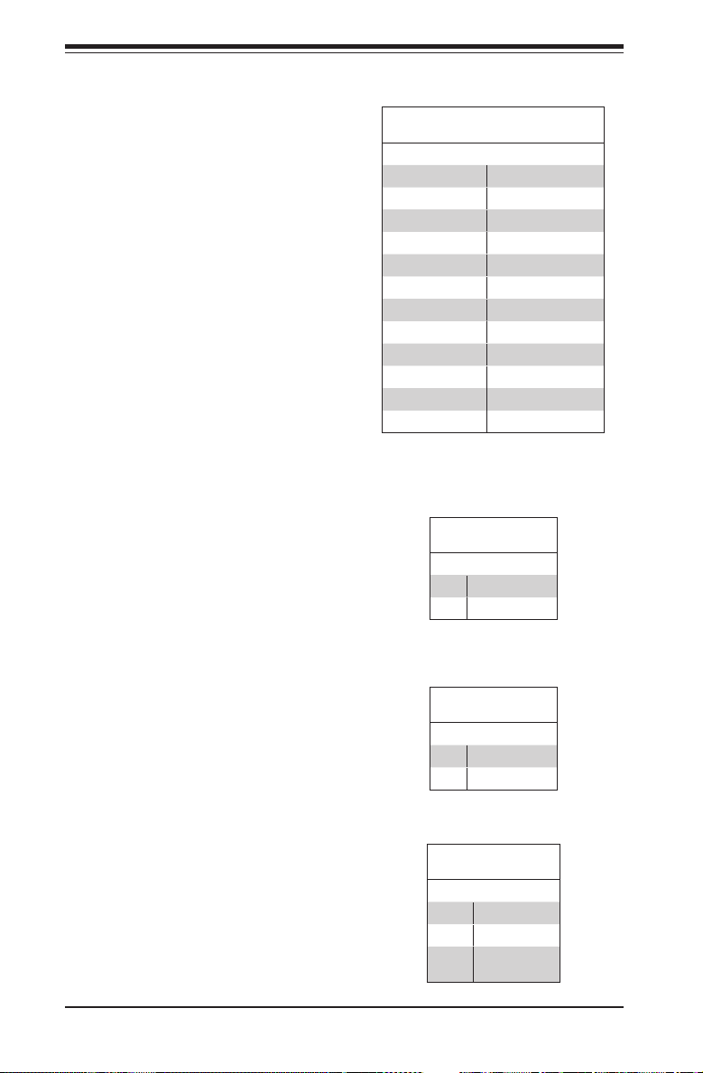
Informational LED
Status Description
Continuously on and red
Blinking red (1Hz) Fan failure, check for an inoperative fan.
Blinking red (0.25Hz) Power failure, check for a non-operational power supply.
Solid blue
Blinking blue (300 m/s)
An overheat condition has occured.
(This may be caused by cable congestion.)
Local UID has been activated. Use this function to locate
the server in a rack mount environment.
Remote UID is on. Use this function to identify the
server from a remote location.
1
NIC1
Indicates network activity on the LAN1 port when ashing.
2
NIC2
Indicates network activity on the LAN2 port when ashing.
3-2
Page 23

Chapter 3: System Interface
HDD
On the SuperServer 5017P-TLN4F/TF, this LED indicates SATA drive activity when
ashing.
Power
Indicates power is being supplied to the system's power supply units. This LED
should normally be illuminated when the system is operating.
3-4 Drive Carrier LEDs
Each drive carrier has two LEDs:
•Green: When illuminated, the green LED on the SATA drive carrier indicates
drive activity. A connection to the SATA backplane enables this LED to blink
on and off when that particular drive is being accessed. Please refer to Chapter
6 for instructions on replacing failed SATA drives.
•Red: When this LED ashes it indicates the drive is rebuilding. When solid on
it indicates a SATA drive failure. If a drive fails, you should be notied by your
system management software. Please refer to Chapter 6 for instructions on
replacing failed drives.
3-3
Page 24

SUPERSERVER 5017P-TLN4F/TF User's Manual
Notes
3-4
Page 25
Chapter 4: System Safety
!
Chapter 4
System Safety
4-1 Electrical Safety Precautions
Basic electrical safety precautions should be followed to protect yourself from harm
and the SuperServer 5017P-TLN4F/TF from damage:
•Be aware of the locations of the power on/off switch on the chassis as well
as the room's emergency power-off switch, disconnection switch or electrical
outlet. If an electrical accident occurs, you can then quickly remove power from
the system.
•Do not work alone when working with high voltage components.
•Power should always be disconnected from the system when removing or install-
ing main system components, such as the serverboard and memory modules.
When disconnecting power, you should rst power down the system with the
operating system rst and then unplug the power cords of all the power supply
units in the system.
•When working around exposed electrical circuits, another person who is familiar
with the power-off controls should be nearby to switch off the power if neces-
sary.
•Use only one hand when working with powered-on electrical equipment. This
is to avoid making a complete circuit, which will cause electrical shock. Use
extreme caution when using metal tools, which can easily damage any electrical
components or circuit boards they come into contact with.
•Do not use mats designed to decrease static electrical discharge as protection
from electrical shock. Instead, use rubber mats that have been specically
designed as electrical insulators.
•The power supply power cords must include a grounding plug and must be
plugged into grounded electrical outlets.
4-1
Page 26
SUPERSERVER 5017P-TLN4F/TF User's Manual
!
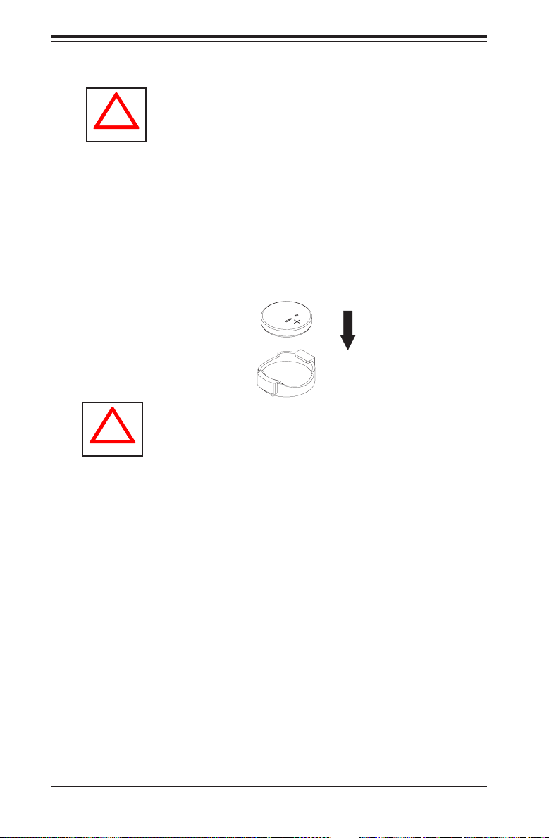
•Serverboard Battery: CAUTION - There is a danger of explosion if the onboard
battery is installed upside down, which will reverse its polarites (see Figure 4-1).
This battery must be replaced only with the same or an equivalent type recom-
mended by the manufacturer (CR2032). Dispose of used batteries according to
the manufacturer's instructions.
•DVD-ROM Laser: CAUTION - this server may have come equipped with a
DVD-ROM drive. To prevent direct exposure to the laser beam and hazardous
radiation exposure, do not open the enclosure or use the unit in any uncon-
ventional way.
•Mainboard replaceable soldered-in fuses: Self-resetting PTC (Positive Tempera-
ture Coefcient) fuses on the mainboard must be replaced by trained service
technicians only. The new fuse must be the same or equivalent as the one
replaced. Contact technical support for details and support.
4-2 General Safety Precautions
Follow these rules to ensure general safety:
•Keep the area around the 5017P-TLN4F/TF clean and free of clutter.
•The 5017P-TLN4F/TF weighs approximately 12 lbs (5.4 kg.) when fully loaded.
When lifting the system, two people at either end should lift slowly with their
feet spread out to distribute the weight. Always keep your back straight and lift
with your legs.
•Place the chassis top cover and any system components that have been re-
moved away from the system or on a table so that they won't accidentally be
stepped on.
•While working on the system, do not wear loose clothing such as neckties and
unbuttoned shirt sleeves, which can come into contact with electrical circuits or
be pulled into a cooling fan.
•Remove any jewelry or metal objects from your body, which are excellent metal
conductors that can create short circuits and harm you if they come into contact
with printed circuit boards or areas where power is present.
4-2
Page 27
Chapter 4: System Safety
!
•After accessing the inside of the system, close the system back up and secure
it to the rack unit with the retention screws after ensuring that all connections
have been made.
4-3 ESD Precautions
Electrostatic discharge (ESD) is generated by two objects with different electrical
charges coming into contact with each other. An electrical discharge is created to
neutralize this difference, which can damage electronic com ponents and printed
circuit boards. The following measures are generally sufcient to neutralize this
difference before contact is made to protect your equipment from ESD:
•Use a grounded wrist strap designed to prevent static discharge.
•Keep all components and printed circuit boards (PCBs) in their antistatic bags
until ready for use.
•Touch a grounded metal object before removing the board from the antistatic
bag.
•Do not let components or PCBs come into contact with your clothing, which may
retain a charge even if you are wearing a wrist strap.
•Handle a board by its edges only; do not touch its components, peripheral chips,
memory modules or contacts.
•When handling chips or modules, avoid touching their pins.
•Put the serverboard and peripherals back into their antistatic bags when not
in use.
•For grounding purposes, make sure your computer chassis provides excellent
conductivity between the power supply, the case, the mounting fasteners and
the serverboard.
4-3
Page 28
SUPERSERVER 5017P-TLN4F/TF User's Manual
!
BATTERY HOLDER
LITHIUM BATTERY
OR
!
4-4 Operating Precautions
Care must be taken to assure that the chassis cover is in place when the 5017P-
TLN4F/TF is operating to assure proper cooling. Out of warranty damage to the
system can occur if this practice is not strictly followed.
Figure 4-1. Installing the Onboard Battery
LITHIUM BATTERY
BATTERY HOLDER
Please handle used batteries carefully. Do not damage the battery in any way; a
damaged battery may release hazardous materials into the environment. Do not
discard a used battery in the garbage or a public landll. Please comply with the
regulations set up by your local hazardous waste management agency to dispose
of your used battery properly.
4-4
Page 29

Chapter 5: Advanced Motherboard Setup
Chapter 5
Advanced Motherboard Setup
This chapter covers the steps required to connect the data and power cables and
install add-on cards. All motherboard jumpers and connections are also described.
A layout and quick reference chart are included in this chapter for your reference.
Remember to completely close the chassis when you have nished working with
the motherboard to better cool and protect the system.
5-1 Handling the Motherboard
Electrostatic Discharge (ESD) can damage electronic com ponents. To prevent dam-
age to any printed circuit boards (PCBs), it is important to handle them very carefully
(see previous chapter). To prevent the motherboard from bending, keep one hand
under the center of the board to support it when handling. The following measures
are generally sufcient to protect your equipment from electric static discharge.
Precautions
•Use a grounded wrist strap designed to prevent ESD.
•Touch a grounded metal object before removing boards from antistatic bags.
•Handle a board by its edges only; do not touch its components, peripheral chips,
memory modules or gold contacts.
•When handling chips or modules, avoid touching their pins.
•Put the motherboard, add-on cards and peripherals back into their antistatic
bags when not in use.
•For grounding purposes, make sure your computer chassis provides excellent
conductivity between the power supply, the case, the mounting fasteners and
the motherboard.
Unpacking
The motherboard is shipped in antistatic packaging to avoid electrical static dis-
charge. When unpacking the board, make sure the person handling it is static
protected.
5-1
Page 30

SUPERSERVER 5017P-TLN4F/TF User's Manual
5-2 Connecting Cables
Now that the motherboard is installed, the next step is to connect the cables to
the board. These include the data cables for the peripherals and control panel and
the power cables.
Connecting Data Cables
The cables used to transfer data from the peripheral devices have been carefully
routed to prevent them from blocking the ow of cooling air that moves through
the system from front to back. If you need to disconnect any of these cables, you
should take care to keep them routed as they were originally after reconnecting
them (make sure the red wires connect to the pin 1 locations). The following data
cables (with their locations noted) should be connected. (See the layout on page
5-10 for connector locations.)
•SATA drive data cables (I-SATA1 ~ I-SATA3)
•Control Panel cable (JF1)
Important! Make sure the the cables do not come into contact with the fans.
Connecting Power Cables
The X9SPV-LN4F/F-3610ME has a 24-pin primary power supply connector (JPW1)
for connection to the ATX power supply. See Section 5-8 for power connector pin
denitions.
Connecting the Control Panel
JF1 contains header pins for various front control panel connectors. See Figure 5-1
for the pin locations of the various front control panel buttons and LED indicators.
All JF1 wires have been bundled into a single cable to simplify this connection. Make
sure the red wire plugs into pin 1 as marked on the board. The other end connects
to the Control Panel PCB board, located just behind the system status LEDs on
the chassis. See Chapter 5 for details and pin descriptions.
5-2
Page 31

Chapter 5: Advanced Motherboard Setup
Figure 5-1. Control Panel Header Pins
2
1
Power Button
Reset Button
X
Vcc
Vcc
Vcc
Vcc
Vcc
X
NMI
Ground
Ground
X
OH/Fan Fail LED
NIC2 LED
NIC1 LED
HDD LED
Power LED
X
Ground
19 20
5-3 Rear I/O Ports
The I/O ports are color coded in conformance with the PC 99 specication. See
Figure 5-2 below for the colors and locations of the various I/O ports.
Figure 5-2. Rear I/O Ports
4
1
3
7
9
6
8
11
10
12
2 5
Rear I/O Ports
1 COM Port 1 7 PS/2 Keyboard/Mouse
2 USB Port 5 8 Gb LAN Port 2
3 USB Port 4 9 Gb LAN Port 1
4 Dedicated IPMI LAN Port 10 Gb LAN Port 4 (X9SPV-LN4F only)
5 USB Port 9 11 Gb LAN Port 3 (X9SPV-LN4F only)
6 USB Port 8 12 VGA Port
5-3
Page 32

SUPERSERVER 5017P-TLN4F/TF User's Manual
5-4 Onboard Processor and Heatsink
The X9SPV-LN4F/F-3610ME features an embedded Intel Core i7 Mobile ECC
processor with an FCBGA 1023 package.
5-5 Installing Memory
Caution! Exercise extreme care when installing or removing DIMM modules to
prevent any possible damage.
Note: Check the Supermicro website for a list of memory modules that have been
validated with the X9SPV-LN4F/F-3610ME motherboard.
How to Install SO DIMMs
1. Insert the desired number of SO DIMMs into the memory slots, starting with
DIMMA1, then DIMMB1. Pay attention to the notch along the bottom of the
module to prevent incorrect DIMM module installation.
2. Insert each SO DIMM module vertically and snap it into place. Repeat step 1
to install DIMMB1 if needed. See instructions on the next page.
Memory Support
The X9SPV-LN4F/F-3610ME motherboard supports up to 16GB of DDR3 ECC
SODIMMs (1333/1066/800 MHz in 2 SODIMM slots).
5-6 Adding PCI Add-On Cards
The 5017P-TLN4F/TF can accommodate a single full-height, half-length add-on
(expansion) card.
Installing an Add-on Card
1. Begin by removing the shield for the PCI slot where the riser card is located.
2. Fully seat the card into the riser card, pushing down with your thumbs evenly
on both sides of the card.
3. Finish by using a screw to secure the top of the card shield to the chassis.
The PCI slot shields protect the motherboard and its components from EMI
and aid in proper ventilation, so make sure there is always a shield covering
each unused slot.
5-4
Page 33

The SO DIMM Socket
Position the SO DIMM
module's bottom key so it
aligns with the receptive
point on the slot. Take
note of the module's side
notches and the locking
clips on the socket.
Insert the SO DIMM module
straight down.
Chapter 5: Advanced Motherboard Setup
Align
Press down until the module
locks into place. The side
clips will automatically secure
the SO DIMM module, locking
it into place.
To Remove:
Use your thumbs to gently
push the side clips near both
ends away from the module.
This should release it from
the slot. Pull the SO DIMM
module upwards.
5-5
Page 34

SUPERSERVER 5017P-TLN4F/TF User's Manual
5-7 Motherboard Details
Figure 5-4. X9SPV-LN4F/F-3610ME Layout
LED3
LED2
JPB1
JL1
JOH1
SLOT1
USB 3.0 2/3
USB 3.0 0/1
FAN3
T-SGPIO1
FAN2
T-SGPIO2
J3
JPUSB1
JPUSB1
COM1
JCOM1
U60
COM1
COM2
JCOM2
COM2
MH2
FAN4
FAN4
U26
LAN2 (TOP)VGA
JWD1
UID
LED3
JVGA1
MH4
MH4
LED2
X9SPV-F
U57
JP1
JPB1
JIPMB1
VGA
1
JWD1
JIPMB1
U21
LAN4
SP1
JL1 JOH1
SP1
U6
KB/MOUSE (TOP)
LAN1 (TOP)
JLAN1JLAN2
LAN2/4
U7
LAN3
USB8/9
KB/MOUSE
LAN1/3
U10
USB 8/9
IPMI (TOP)
USB4/5
J1
IPMI
U22
USB 4/5
JBT1
I-SATA5 I-SATA4
I-SATA3 I-SATA2
U3
I-SATA1 3.0 I-SATA0 3.0
CPU1
FAN1
FAN1
LED1
JDIMM1
I-SATA5
I-SATA4
JDIMM2
I-SATA2
I-SATA3
MH6
JWP1:WRITE PROTECT
T-SGPIO2T-SGPIO1
I-SATA0I-SATA1
LED1
JD1
F6
JWP1
JPI2C1
PWR I2C
JF1
JSD1:SATA
DOM POWER
JTPM1:TPM/PORT80
JTPM1
JSD1
J20USB1
JPK1
P1-DIMMA1
P1-DIMMB1
USB6/7
FAN2FAN3
DIMMA1
DIMMB1
MH7
JPW1
USB 6/7
JWP1
JPI2C1
JF1
JSD1
JD1
JTPM1
Notes
• " " indicates the location of "Pin 1".
•Jumpers not indicated are for test purposes only.
5-6
JPW1
Page 35

Chapter 5: Advanced Motherboard Setup
X9SPV-LN4F/F-3610ME Quick Reference
Connector Description
LED1 Standby Power LED
LED2 IPMI Heartbeat LED (X9SPV-F only)
LED3 Unsupported Memory LED
SLOT1 PCI-E x16 Gen 2 Slot
JL1 Chassis Intrusion Header
JOH1 Overheat LED
USB 0/1, USB 2/3 USB 3.0 Headers
USB 6/7 USB 2.0 Header
USB 4/5, USB 8/9 Backpanel USB Ports
FAN1~4 CPU Fan, System Fan and Auxilliary Fan Headers
T-SGPIO1, T-SGPIO2 Serial General Purpose I/O Headers
JPI2C1 JPI2C, PWR supply (I2C) System Management Bus
JF1 Front Panel Control Header
JSD1 DOM (Disk on Module) Power Connector
JTPM1 TPM Header
SP1 Onboard Speaker/Buzzer
JD1 Power LED/Speaker Header
I-SATA1~I-SATA6 SATA Ports (White connectors: SATA 3, Black: SATA 2)
JPW1 24-Pin ATX Power Connector
DIMMA1, DIMMB1 SODIMM Memory Sockets
COM1, COM2 Serial Ports (COM1: Backpanel, COM2 Onboard Header)
IPMI IPMI Port (X9SPV-F only)
KB/MOUSE Combination PS/2 Keyboard or Mouse Port
LAN1, LAN2 LAN1, LAN2 Gb Ethernet Ports
LAN3, LAN4 LAN3, LAN4 Gb Ethernet Ports (X9SPV-LN4 only)
VGA VGA Port
JIPMB1 4-pin External BMC I2C Header (for an IPMI card)
CPU1 CPU / Processor
Jumper Description Default Setting
JPB1 BMC (IPMI) Enable/Disable Pins 1-2 (Enabled)
JBT1 CMOS Clear See Section 5-9
JWD1 Watch Dog Timer Pins 1-2 (Reset)
JWP1 BIOS Write Protect Pins 1-2 (Enabled)
JPUSB1 USB Wake-up Pins 1-2 (Enabled)
5-7
Page 36
SUPERSERVER 5017P-TLN4F/TF User's Manual
5-8 Connector Denitions
Power Connectors
The 24-pin power connector is used
to provide power to the motherboard.
This connector meets the SSI EPS
12V specication. See the tables on
the right for pin denitions.
ATX Power 24-pin Connector
Pin Denitions
Pin# Denition Pin # Denition
13 +3.3V 1 +3.3V
14 -12V 2 +3.3V
15 COM 3 COM
16 PS_ON 4 +5V
17 COM 5 COM
18 COM 6 +5V
19 COM 7 COM
20 Res (NC) 8 PWR_OK
21 +5V 9 5VSB
22 +5V 10 +12V
23 +5V 11 +12V
24 COM 12 +3.3V
NC = No Connection
Power Button
The Power On connection is on pins
1 and 2 of JF1. These should be con-
nected to the chassis power button.
See p. 5-4 and the table on the right
for pin denitions.
Reset Button
The Reset Button connection is
located on pins 3 and 4 of JF1 and
attaches to the reset switch on the
computer chassis. See p. 5-4 and the
table on the right for pin denitions.
Overheat (OH)/Fan Fail LED
Connect an LED cable to pins 7 and
8 of JF1 to provide advanced warn-
ings of chassis overheat or fan failure.
Refer to the table on the right for pin
denitions.
5-8
Power Button
Pin Denitions (JF1)
Pin# Denition
1 Power Signal
2 Ground
Reset Button
Pin Denitions (JF1)
Pin# Denition
3 Reset
4 Ground
OH/Fan Fail Indicator
Status
State Denition
Off Normal
On Overheat
Flash-
Fan Fail
ing
Page 37

NIC2 LED
The LED connections for LAN2 are
on pins 9 and 10 of JF1. Attach an
LED cable to display network activ-
ity. See the table on the right for pin
denitions.
NIC1 LED
The LED connections for LAN1 are
on pins 11 and 12 of JF1. Attach an
LED cable to display network activ-
ity. See the table on the right for pin
denitions.
HDD LED
The HDD LED connection is located
on pins 13 and 14 of JF1. Attach a
hard drive LED cable here to display
disk activity (for any hard drive ac-
tivities on the system, including Serial
ATA and IDE). See the table on the
right for pin denitions.
Chapter 5: Advanced Motherboard Setup
NIC2 LED
Pin Denitions (JF1)
Pin# Denition
9 Vcc
10 Ground
NIC1 LED
Pin Denitions (JF1)
Pin# Denition
11 Vcc
12 Ground
HDD LED
Pin Denitions (JF1)
Pin# Denition
13 Vcc
14 HD Active
Power On LED
The Power On LED connector is lo-
cated on pins 15 and 16 of JF1. This
connection is used to provide LED
indication of power being supplied to
the system. See the table on the right
for pin denitions.
NMI Button
The non-maskable interrupt button
header is located on pins 19 and 20
of JF1. See the table on the right for
pin denitions.
5-9
Power LED
Pin Denitions (JF1)
Pin# Denition
15 +3.3V
16 Control
NMI Button
Pin Denitions (JF1)
Pin# Denition
19 Control
20 Ground
Page 38

SUPERSERVER 5017P-TLN4F/TF User's Manual
Pin# Denition
1 P2V5SB 10 SGND
Ethernet Ports
Four Ethernet ports are located on the
I/O backplane. A dedicated IPMI LAN
port is also included to provide KVM
support for IPMI 2.0. These ports ac-
cept RJ45 type cables.
Fan Headers
There are three fan headers on the
motherboard, all of which are 4-pin
fans (Fan 1-Fan 8). Pins 1-3 of the
fan headers are backward compatible
with the traditional 3-pin fans. (Fan
speed control is supported with 4-pin
fans only.) See the table on the right
for pin denitions. The onboard fan
speeds are controlled by IPMI.
2 TD0+ 11 Act LED
3 TD0- 12 P3V3SB
4 TD1+ 13 Link 100 LED (Yel-
5 TD1- 14 Link 1000 LED
6 TD2+ 15 Ground
7 TD2- 16 Ground
8 TD3+ 17 Ground
9 TD3- 18 Ground
LAN Ports
Pin Denition
low, +3V3SB)
(Yellow, +3V3SB)
Fan Header
Pin Denitions
Pin# Denition
1 Ground (Black)
2 +12V (Red)
3 Tachometer
4 PWR Modulation
Chassis Intrusion
The Chassis Intrusion header is des-
ignated JL1. Attach a chassis intrusion
cable from the chassis to inform you of
a chassis intrusion when the chassis
is opened
Serial Ports
Two serial ports are included on the
motherboard. COM1 is a backpanel
port and COM2 is a header located
just behind COM1 to provide front
access support. See the table on the
right for pin denitions.
Chassis Intrusion
Pin Denitions
Pin# Denition
1 Intrusion Input
2 Ground
Serial Port Pin Denitions
(COM1/COM2)
Pin # Denition Pin # Denition
1 DCD 6 DSR
2 RXD 7 RTS
3 TXD 8 CTS
4 DTR 9 RI
5 Ground 10 NC
5-10
Page 39

Internal Speaker
The internal speaker, located at SP1,
can be used to provide audible indica-
tions for various beep codes. See the
table on the right for pin denitions..
Universal Serial Bus (USB)
Four Universal Serial Bus ports (USB
4/5, 8/9) are located on the I/O back-
panel. Additionally, one USB 2.0 header
(USB 6/7) and two USB 3.0 headers
(USB 0/1, 2/3) are also located on the
motherboard to provide front chassis
access (cables are not included.) See
the tables on the right for pin denitions.
Chapter 5: Advanced Motherboard Setup
Internal Buzzer (SP1)
Pin Denition
Pin# Denitions
Pin 1 Pos. (+) Beep In
Pin 2 Neg. (-) Alarm
Back Panel USB
Type A USB 10 Pin Denitions
Pin# Denition Pin# Denition
1 +5V 5 +5V
2 USB_PN 6 USB_PN
3 USB_PP 7 USB_PP
4 Ground 8 Ground
Front Panel USB 2.0
Pin Denitions
Pin # Denition Pin # Denition
1 +5V 6 +5V
2 USB_PN 7 USB_PN
3 USB_PP 8 USB_PP
4 Ground 9 Ground
5 NA 10 Key
Speaker
LAN Ports (LAN1~LAN4)
Two gigabit LAN ports are located on
the I/O back panel (four on the X9SPV-
LN4F). These ports accept RJ45 type
cables. These are used to connect the
motherboard to a network. On product
models X9SPV-F and X9SPV-LN4F, an
IPMI port is also provided for remote
management through a TCP/IP network.
5-11
RJ45/LAN
Pin Denitions
Pin # Denition Pin # Denition
1 TX_D1+ 5 BI_D3-
2 TX_D1- 6 RX_D2-
3 RX_D2+ 7 BI_D4+
4 BI_D3+ 8 BI_D4-
Page 40

SUPERSERVER 5017P-TLN4F/TF User's Manual
Power LED/Speaker
On the JD1 header, pins 1-3 are for
a power LED and pins 4-7 are for the
speaker. Close pins 4-7 with a jumper
to use an external speaker. If you wish
to use the onboard speaker, please
close pins 6-7. See the table on the
right for speaker pin denitions.
PWR LED Connector
Pin Denitions
Pin Setting Denition
Pin 1 Anode (+)
Pin2 Cathode (-)
Pin3 NA
Speaker Connector
Pin Settings
Pin Setting Denition
Pins 4-7 External Speaker
Pins 6-7 Internal Speaker
T-SGPIO Headers
The SGPIO (Serial General Purpose
Input/Output) headers are used to
communicate with the enclosure
management chip on the backplane.
See the table on the right for pin
denitions.
Overheat/Fan Fail LED
The JOH1 header is used to connect
an LED indicator to provide warnings
of chassis overheating and fan failure.
This LED will blink when a fan failure
occurs. Refer to the table on the right
for pin denitions.
T-SGPIO Headers
Pin Denitions
Pin# Denition Pin Denition
1 NC 2 NC
3 Ground 4 DATA Out
5 Load 6 Ground
7 Clock 8 NC
Overheat LED
Pin Denitions
Pin# Denition
1 5VDC
2 OH Active
OH/Fan Fail LED
Status
State Message
Solid Overheat
Blinking Fan Fail
5-12
Page 41

Chapter 5: Advanced Motherboard Setup
DOM Power Connector
A power connector for SATA DOM
(Disk On Module) devices is located at
JSD1. Connect an appropriate cable
here to provide power support for your
DOM devices.
Power Supply SMBus I2C Header
The power System Management Bus
header at JPI2C2 is used to monitor
the status of the power supply, fan and
system temperature. See the table on
the right for pin denitions.
IPMB
A System Management Bus header for
IPMI 2.0 is located at IPMB. Connect
the appropriate cable here to use the
IPMB I2C connection on your system.
DOM PWR
Pin Denitions
Pin# Denition
1 +5V
2 Ground
3 Ground
PWR SMB
Pin Denitions
Pin# Denition
1 Clock
2 Data
3 PWR Fail
4 Ground
5 +3.3V
IPMB Header
Pin Denitions
Pin# Denition
1 Data
2 Ground
3 Clock
4 No Connection
5-13
Page 42

SUPERSERVER 5017P-TLN4F/TF User's Manual
5-9 Jumper Settings
Explanation of Jumpers
To modify the operation of the mother-
board, jumpers can be used to choose
between optional settings. Jumpers
Connector
Pins
create shorts between two pins to
change the function of the connector.
Pin 1 is identied with a square solder
Jumper
pad on the printed circuit board. See
the motherboard layout pages for
jumper locations.
Setting
Note: On a two-pin jumper, "Closed"
means the jumper is on both pins and
"Open" means the jumper is either on
only one pin or completely removed.
CMOS Clear
JBT1 is used to clear CMOS (which will also clear any passwords). Instead of pins,
this jumper consists of contact pads to prevent accidentally clearing the contents
of CMOS.
To clear CMOS,
3 2 1
3 2 1
1. First power down the system and unplug the power cord(s).
2. With the power disconnected, short the CMOS pads with a metal object such
as a small screwdriver.
3. Remove the screwdriver (or shorting device).
4. Reconnect the power cord(s) and power on the system.
Note: Do not use the PW_ON connector to clear CMOS.
BIOS Write Protect (JWP1)
The BIOS Write-Protect jumper (JWP1)
is used to protect the BIOS rmware from
accidentally being erased. Close pins 2-3
before reprogramming the rmware. Oth-
erwise, this jumper should be enabled
BMC IPMI Enable/Disable
Jumper Settings
Setting Denition
Pins 1-2 Enabled (Default)
Pins 2-3 Disabled
(pins 1-2) during normal operation.
5-14
Page 43

Watch Dog Enable/Disable
Jumper JWD controls the Watch Dog
function. Watch Dog is a system moni-
tor that can reboot the system when a
software application hangs. Jumping
pins 1-2 will cause WD to reset the sys-
tem if an application hangs. Jumping
pins 2-3 will generate a non-maskable
interrupt signal for the application that
hangs. See the table on the right for
jumper settings. Watch Dog must also
be enabled in BIOS.
BMC Enable/Disable
JPB1 is used to enable or disable the
BMC (Baseboard Management Con-
trol) chip and the onboard IPMI con-
nection. This jumper is used together
with the IPMI settings in the BIOS.
See the table on the right for jumper
settings.
Chapter 5: Advanced Motherboard Setup
Watch Dog
Jumper Settings
Setting Denition
Pins 1-2 Reset
Pins 2-3 NMI
Open Disabled
BMC Enable
Jumper Settings
Setting Denition
Pins 1-2 BMC Enabled
Pins 2-3 Disabled
USB Wake-Up (JPUSB1)
Use the JPUSB1 jumper to enable system
"wake-up" via a USB device. This jumper
allows you to "wake-up" the system by
pressing a key on the USB keyboard or by
clicking the USB mouse of your system.
The JPUSB1 jumper is used together with
the USB Wake-Up function in the BIOS.
Enable both the jumper and the BIOS set-
ting to activate this function. See the table
on the right for jumper settings and jumper
connections.
Note: The default jumper setting is "Dis-
abled". When the "USB Wake-Up" function
is enabled, it will be active on all USB ports.
5-15
USB Wake-Up
Jumper Settings
Jumper Setting Denition
Pins 1-2 Enabled
Pins 2-3 Disabled (Default)
Page 44

SUPERSERVER 5017P-TLN4F/TF User's Manual
5-10 Onboard Indicators
LAN LEDs
The Ethernet ports (located beside the
VGA port) have two LEDs. On each
port, the yellow LED ashes to indi-
cate activity while the other LED may
be green, amber or off to indicate the
speed of the connection. See the table
on the right for the functions associ-
ated with the connection speed LED.
Standby Power LED (LED1)
An Onboard Power LED is located
at LED1 on the motherboard. When
LED1 is on, the AC power cable is
connected and the power supply hard
switch is on. The system may be on
standby or running.
IPMI Heartbeat LED (LED2)
An IPMI Heartbeat LED is located at
LED2. When LED2 blinks, it means
that IPMI is enabled and function-
ing properly. For the X9SPV-F and
X9SPV-LN4F only.
LAN1/2 LED
(Connection Speed Indicator)
LED Color Denition
Off NC or 10 Mbps
Green 100 Mbps
Amber 1 Gbps
Onboard PWR LED (LED1)
LED Status
Status Denition
Off System Off (Soft Switch)
On Power is Detected
IPMI Heartbeat LED (LED2)
LED Settings
Status Denition
Green: Blinking IPMI is ready for use
Off IPMI Disabled
Overheat / Fan Fail (LED3)
LED3 is located next to the VGA port.
This indicator alerts of either a Fan
Failure, or System Overheat.
OH/Fan Fail LED Indicator (LED3)
Status Denition
Yellow: Blinking with
continuous beep
Yellow: Solid with
continuous beep
Off Normal
5-16
LED Settings
Fan Failure
System Overheat
Page 45

5-11 SATA and SAS Ports
Serial ATA Ports
Two Serial ATA (SATA) 3.0 connec-
tors (I-SATA 0/1) are located on the
motherboard. In addition, four SATA
2.0 (I-SATA 2~5) connectors are also
located on the board. The SATA 3.0
ports support RAID 0, 1 while the
SATA 2.0 ports support RAID 0, 1, 5
&10See the table on the right for pin
denitions.
Chapter 5: Advanced Motherboard Setup
SATA Port
Pin Denitions
Pin# Denition Pin Denition
1 Ground 2 TXP
3 TXN 4 Ground
5 RXN 6 RXP
7 Ground
5-17
Page 46

SUPERSERVER 5017P-TLN4F/TF User's Manual
5-12 Installing Software
After the hardware has been installed, you should rst install the operating system
and then the drivers. The necessary drivers are all included on the Supermicro CDs
that came packaged with your motherboard.
Driver/Tool Installation Display Screen
Note: Click the icons showing a hand writing on paper to view the readme les
for each item. Click the computer icons to the right of these items to install each
item (from top to the bottom) one at a time. After installing each item, you must
re-boot the system before moving on to the next item on the list. The bottom
icon with a CD on it allows you to view the entire contents of the CD.
5-18
Page 47

Chapter 5: Advanced Motherboard Setup
SuperDoctor III
The SuperDoctor® III program is a Web base management tool that supports remote
management capability. It includes Remote and Local Management tools. The local
management is called SD III Client. The SuperDoctor III program included on the
CD-ROM that came with your motherboard allows you to monitor the environment
and operations of your system. SuperDoctor III displays crucial system information
such as CPU temperature, system voltages and fan status. See the Figure below
for a display of the SuperDoctor III interface.
Note: The default User Name and Password for SuperDoctor III is ADMIN / ADMIN.
Note: When SuperDoctor is rst installed, it adopts the temperature threshold set-
tings that have been set in BIOS. Any subsequent changes to these thresholds
must be made within SuperDoctor, as the SuperDoctor settings override the BIOS
settings. To set the BIOS temperature threshold settings again, you would rst need
to uninstall SuperDoctor.
Supero Doctor III Interface Display Screen (Health Information)
5-19
Page 48

SUPERSERVER 5017P-TLN4F/TF User's Manual
Supero Doctor III Interface Display Screen (Remote Control)
Note: The SuperDoctor III program and User's Manual can be downloaded from the
Supermicro web site at http://www.supermicro.com/products/accessories/software/
SuperDoctorIII.cfm.
For Linux, we recommend using SuperDoctor II.
5-20
Page 49

Chapter 5: Advanced Motherboard Setup
5-21
Page 50

Chapter 6: Advanced Chassis Setup
Chapter 6
Advanced Chassis Setup
This chapter covers the steps required to install components and perform mainte-
nance on the SC504-203B chassis. For component installation, follow the steps in
the order given to eliminate the most common problems encountered. If some steps
are unnecessary, skip ahead to the step that follows.
Tools Required: The only tool you will need to install components and perform
maintenance is a Philips screwdriver.
6-1 Static-Sensitive Devices
Electrostatic discharge (ESD) can damage electronic com ponents. To prevent
damage to any printed circuit boards (PCBs), it is important to handle them very
carefully. The following measures are generally sufcient to protect your equipment
from ESD damage.
Precautions
•Use a grounded wrist strap designed to prevent static discharge.
•Touch a grounded metal object before removing any board from its antistatic
bag.
•Handle a board by its edges only; do not touch its components, peripheral chips,
memory modules or gold contacts.
•When handling chips or modules, avoid touching their pins.
•Put the serverboard, add-on cards and peripherals back into their antistatic
bags when not in use.
•For grounding purposes, make sure your computer chassis provides excellent
conductivity between the power supply, the case, the mounting fasteners and
the serverboard.
Unpacking
The serverboard is shipped in antistatic packaging to avoid static damage. When
unpacking the board, make sure the person handling it is static protected.
6-1
Page 51

SUPERSERVER 5017P-TLN4F/TF User's Manual
Figure 6-1. Front and Rear Chassis Views
Control Panel
Rear I/O Ports (see Figure 5-2)
Low-prole PCI SlotPower Supply
6-2 Control Panel
The control panel (located on the front of the chassis) must be connected to the
JF1 connector on the serverboard to provide you with system status indications. A
ribbon cable has bundled these wires together to simplify the connection. Connect
the cable from JF1 on the serverboard to the Control Panel PCB (printed circuit
board). Make sure the red wire plugs into pin 1 on both connectors. Pull all excess
cabling out of the airow path. The LEDs inform you of system status.
See Chapter 3 for details on the LEDs and the control panel buttons. Details on
JF1 can be found in Chapter 5.
6-2
Page 52

6-3 Removing the Chassis Cover
1
2
Chapter 6: Advanced Chassis Setup
1
3
1
2
1
2
Figure 6-2. Removing the Chassis Cover
Removing the Chassis Cover
1. Power down the system and disconnect the power cord from the back of the
power supply.
2. Remove the ve screws that hold the chassis cover in place. There are two
screws on each side of the chassis, and one screw on the back.
3. Once the screws have been removed, lift the cover upward to remove it from
the chassis.
Caution: Except for short periods of time, do NOT operate the server without the
cover in place. The chassis cover must be in place to allow proper airow and prevent
overheating.
6-3
Page 53

SUPERSERVER 5017P-TLN4F/TF User's Manual
6-4 System Fans (Optional)
Up to three optional system fans may be installed in the SC504 chassis.
Installing Optional System Fans
1. Position the dual system fan housing in the front of the chassis, facing for-
ward as illustrated above, in front of the motherboard.
2. Align the mounting holes in the fan housing with the holes in the oor of the
chassis.
3. Secure the dual fan housing to the chassis with the screws provided.
4. Position the single system fan to the left of the dual system fans.
5. Align the mounting holes in the single fan housing with the holes in the oor
of the chassis.
6. Secure the single fan housing to the oor of the chassis.
7. Connect the fan cables to the motherboard and put the cover back on the
chassis.
6-5 Installing Hard Drives
Follow the instructions that follow to install either four 2.5" or two 3.5" hard drives.
Installing 3.5" Hard Drives
1. Power down the server, disconnect the power cord from the power supply and
remove the cover.
2. Place the 3.5" hard drive into the chassis as illustrated above.
3. Secure the hard drive to the chassis oor by inserting four screws up through
the underside of the chassis.
4. Connect the hard drive wiring, reinstall the chassis cover and power cord,
then power up the server.
6-4
Page 54

Chapter 6: Advanced Chassis Setup
Installing 2.5" Hard Drives
2.5" hard drives may be installed in several different congurations. Review the
supported conguration options on page 6-6.
1. Power down the server, disconnect the power cord from the power supply and
remove the cover.
2. Install up to four 2.5" hard drive(s) into the hard drive bracket(s) and secure
them to the bracket with the screws provided. (See page 6-6 for supported
conguration options.)
3. Place the hard drive and bracket into the chassis as illustrated in Figure 6-3.
If up to four 2.5" hard drives are desired, rotate the hard drive brackets ninety
degrees and place them side by side before attaching them to the chassis.
4. Secure the hard drive bracket(s) to the chassis oor by inserting the screws
up through the underside of the chassis.
5. Expansion cards must be installed after installing the 2.5" hard drives.
6. Connect the hard drive wiring, reinstall the chassis cover and power cord,
then power up the server
Note: bracket part number is MCP-220-000440N
6-5
Page 55

SUPERSERVER 5017P-TLN4F/TF User's Manual
Hard Drive Conguration Options
2.5" and 3.5" hard drives are supported in the following congurations:
Figure 6-3. Installing Hard Drives
One 3.5" Hard Drive and one Low Prole
Two 2.5" Hard Drives and One Full-Height, Half-
Length Expansion Card
In a Double Bracket, Four HDD's Total,
Two 2.5" HDDs
No Expansion Card
Expansion Card
Two 3.5" Hard Drives and No
Expansion Card
6-6
Page 56

Chapter 6: Advanced Chassis Setup
6-6 Installing an Expansion Card
The SC504 chassis includes a PCI slot for an optional full-height, half-length ex-
pansion card. A riser card is required in order to connect the expansion card to the
motherboard. For further information on expansionon cards and risers cards, visit
the Supermicro website at www.supermicro.com
Expansion Card
Clip
Figure 6-4. Locating the Expansion Card Clip
Installing the Expansion Card
1. Power down the server, disconnect the power cord from the power supply and
remove the cover. Locate the expansion card clip on the back of the chassis
2. Remove the screws holding the expansion card clip and the PCI slot cover
which covers the PCI slot opening in the back of the chassis.
3. Remove the expansion card clip and the PCI slot cover from the chassis.
Expansion Card Clip
PCI Slot Cover
Riser Card Slot
Figure 6-5. Installing the Expansion Card and Riser Card
6-7
Page 57

SUPERSERVER 5017P-TLN4F/TF User's Manual
4. Outside of the chassis, put the expansion card and the riser card together by
inserting the expansion card into the riser card.
5. Simultaneously insert the PCI slot bracket of the expansion card into the open
PCI slot and insert the riser card in to the riser card slot on the motherboard.
Figure 6-6. Installing the Expansion Card
6. Replace the expansion card clip and screw it onto the chassis to hold the
expansion card in place.
7. Replace the cover onto the chassis, reconnect the power cord and power up
the server.
Figure 6-7. Replacing the Expansion Card Clip
6-8
Page 58

Chapter 6: Advanced Chassis Setup
6-7 Power Supply
The SC504 chassis has a 200 Watt power supply. This power supply is auto-switch-
ing capable. This enables it to automatically sense and operate at a 100v to 240v
input voltage.In the unlikely event that the power supply module fails, the system
will shut down and you will need to replace the power supply module. New units
can be ordered directly from Supermicro (see contact information in the Preface).
Replacing the Power Supply
Replacing the Power Supply
1. Power down the system, disconnect the power cord and remove the chassis
cover.
2. Disconnect all wiring from the power supply.
3. Remove the four screws which hold the power supply in the chassis. Two rear
mounting screws are located on the rear of the power supply. Two bottom
mounting screws are accessed on the underside of the chassis and extend
upwards through the mounting thru holes, to hold the power supply in place.
Set the screws aside for later use.
Power Supply
Mounting Thru Holes
Insert Bottom
Mounting Screws
from Underside
Figure 6-8. Installing the Power Supply
6-9
Rear Mounting
Screws
Page 59

SUPERSERVER 5017P-TLN4F/TF User's Manual
4. Remove the power supply from the chassis.
5. Align the mounting thru holes on the power supply with the mounting holes
in the chassis and reattach the power supply to the chassis using the four
screws which were previously set aside
6. Reconnect the wiring and the power cord to the power supply, replace the
cover and power up the server.
6-10
Page 60

Chapter 7: BIOS
Chapter 7
BIOS
7-1 Introduction
This chapter describes the AMI BIOS Setup Utility for the X9SPV-F/LN4F moth-
erboard. The AMI ROM BIOS is stored in a Flash EEPROM and can be easily
updated. This chapter describes the basic navigation of the AMI BIOS Setup Utility
setup screens.
Note: For instructions on BIOS recovery, please refer to the instruction guide posted
at http://www.supermicro.com/support/manuals/.
Starting BIOS Setup Utility
To enter the AMI BIOS Setup Utility screens, press the <Delete> key while the
system is booting up.
Note: In most cases, the <Delete> key is used to invoke the AMI BIOS setup screen.
There are a few cases when other keys are used, such as <F1>, <F2>, etc.
Each main BIOS menu option is described in this manual. The Main BIOS setup
menu screen has two main frames. The left frame displays all the options that can
be congured. Grayed-out options cannot be congured. Options in blue can be
congured by the user. The right frame displays the key legend. Above the key
legend is an area reserved for a text message. When an option is selected in the
left frame, it is highlighted in white. Often a text message will accompany it. (Note:
the AMI BIOS has default text messages built in. Supermicro retains the option to
include, omit, or change any of these text messages.)
The AMI BIOS Setup Utility uses a key-based navigation system called "hot keys".
Most of the AMI BIOS setup utility "hot keys" can be used at any time during the
setup navigation process. These keys include <F1>, <F10>, <Enter>, <ESC>, ar-
row keys, etc.
Note: Options printed in Bold are default settings.
How To Change the Conguration Data
The conguration data that determines the system parameters may be changed by
entering the AMI BIOS Setup utility. This Setup utility can be accessed by pressing
<Del> at the appropriate time during system boot.
7-1
Page 61

SUPERSERVER 5017P-TLN4F/TF User's Manual
How to Start the Setup Utility
Normally, the only visible Power-On Self-Test (POST) routine is the memory test.
As the memory is being tested, press the <Delete> key to enter the main menu of
the AMI BIOS Setup Utility. From the main menu, you can access the other setup
screens. An AMI BIOS identication string is displayed at the left bottom corner of
the screen, below the copyright message.
Warning! Do not upgrade the BIOS unless your system has a BIOS-related
issue. Flashing the wrong BIOS can cause irreparable damage to the
system. In no event shall Supermicro be liable for direct, indirect, special,
incidental, or consequential damages arising from a BIOS update. If you
have to update the BIOS, do not shut down or reset the system while the
BIOS is updating. This is to avoid possible boot failure.
7-2 Main Setup
When you rst enter the AMI BIOS Setup Utility, you will enter the Main setup screen.
You can always return to the Main setup screen by selecting the Main tab on the
top of the screen. The Main BIOS Setup screen is shown below.
7-2
Page 62

Chapter 7: BIOS
System Overview: The following BIOS information will be displayed:
System Time/System Date
Use this option to change the system time and date. Highlight System Time or Sys-
tem Date using the arrow keys. Enter new values through the keyboard. Press the
<Tab> key or the arrow keys to move between elds. The date must be entered in
Day MM/DD/YY format. The time is entered in HH:MM:SS format. (Note: The time
is in the 24-hour format. For example, 5:30 P.M. appears as 17:30:00.)
Supermicro X9SPV-F/LN4F
Version: This item displays the version of the BIOS used in the system.
Build Date: This item displays the day this version of BIOS was built.
Processor
This displays the processor type, speed, physical count, and logical count.
System Memory
This displays the size of memory available in the system.
7-1
Page 63

SUPERSERVER 5017P-TLN4F/TF User's Manual
7-3 Advanced Setup Congurations
Use the arrow keys to select Boot Setup and hit <Enter> to access the submenu
items:
BOOT Feature
Quiet Boot
This option allows the bootup screen options to be modied between POST mes-
sages or the OEM logo. Select Disabled to display the POST messages. Select
Enabled to display the OEM logo instead of the normal POST messages. The op-
tions are Enabled and Disabled.
Option ROM Display Messages
This sets the display mode for Option ROM. The options are Force BIOS and
Keep Current.
Bootup Num-Lock
This feature selects the Power-on state for Numlock key. The options are Off
and On.
7-4
Page 64

Chapter 7: BIOS
Wait For 'F1' If Error
This forces the system to wait until the 'F1' key is pressed if an error occurs. The
options are Disabled and Enabled.
INT19 Trap Response
The Interrupt 19 (INT19) feature determines how the BIOS will react to INT19 trap-
ping by Option ROM. If set to Immediate, BIOS will execute the trap right away. If
set to Postponed, BIOS will execute the trap during legacy boot. The options are
Immediate and Postponed
Watch Dog Function
If enabled, the Watch Dog Timer will allow the system to reboot when it is inactive
for more than 5 minutes. The options are Enabled and Disabled.
Power Button Function
This feature controls how the system shuts down when the power button is pressed.
Select 4-Seconds Override to force the user to press and hold the Power Button for
4 seconds before the system turns off. Select Instant Off if you want the system to
instantly power off when the Power Button is pressed. The options are 4 Seconds
Override and Instant Off.
Restore on AC Power Loss
Use this feature to set the power state after a power outage. Select Stay-Off for the
system power to remain off after a power loss. Select Power-On for the system
power to be turned on after a power loss. Select Last State to allow the system
to resume its last state before a power loss. The options are Power-On, Stay-Off
and Last State.
Processor and Clock Options
Warning: Take Caution when changing the Advanced settings. An incorrect
value, a very high DRAM frequency or incorrect DRAM timing may cause
system to become unstable. When this occurs, revert to the default setting.
The top section is for informational purposes only and displays CPU informa-
tion including type, speed, number of cores, etc.
Hyper Threading
Set to Enabled to use the processor's Hyper Threading Technology feature. The
options are Enabled and Disabled.
7-1
Page 65

SUPERSERVER 5017P-TLN4F/TF User's Manual
Active Processor Cores
Set to Enabled to use a processor's Second Core and beyond. (Please refer to
Intel's web site for more information.) The options are All, 1, 2, and 3.
Limit CPUID Maximum
This feature allows the user to set the maximum CPU ID value. Enable this function
to boot the legacy operating systems that cannot support processors with extended
CPUID functions. The options are Enabled and Disabled (for the Windows OS.).
Execute-Disable Bit (Available when supported by the OS and the CPU)
Set to Enabled to enable the Execute Disable Bit which will allow the processor
to designate areas in the system memory where an application code can execute
and where it cannot, thus preventing a worm or a virus from ooding illegal codes
to overwhelm the processor or damage the system during an attack. The default is
Enabled. (Refer to Intel and Microsoft Web Sites for more information.)
Intel® Virtualization Technology (Available when supported by the CPU)
Select Enabled to use the feature of Virtualization Technology to allow one plat-
form to run multiple operating systems and applications in independent partitions,
creating multiple "virtual" systems in one physical computer. The options are
Enabled and Disabled.
Note: If there is any change to this setting, you will need to power off and
restart the system for the change to take effect. Please refer to Intel’s
web site for detailed information.
Hardware Prefetcher (Available when supported by the CPU)
If set to Enabled, the hardware pre fetcher will pre fetch streams of data and instruc-
tions from the main memory to the L2 cache in the forward or backward manner to
improve CPU performance. The options are Disabled and Enabled.
Adjacent Cache Line Prefetch (Available when supported by the CPU)
The CPU fetches the cache line for 64 bytes if this option is set to Disabled. The
CPU fetches both cache lines for 128 bytes as comprised if Enabled.
Clock Spread Spectrum
Select Enable to use the feature of Clock Spectrum, which will allow the BIOS to
monitor and attempt to reduce the level of Electromagnetic Interference caused by
the components whenever needed. Select Disabled to enhance system stability.
The options are Disabled and Enabled.
7-6
Page 66

Chapter 7: BIOS
CPU PPM Conguration
Power Technology
This feature determines what power-saving scheme the motherboard uses. The
options are Disabled, Energy Efcient and Custom. If Custom is selected, the
following options become available:
EIST
EIST (Enhanced Intel SpeedStep Technology) allows the system to automati-
cally adjust processor voltage and core frequency in an effort to reduce
power consumption and heat dissipation. Please refer to Intel’s web site for
detailed information. The options are Disabled and Enabled.
Turbo Mode
This feature allows processor cores to run faster than marked frequency in
specic conditions. The options are Disabled and Enabled.
CPU C3 Report, CPU C6 Report
This BIOS feature enables or disables C3 (ACPI C2) and C6 (ACPI C3)
reporting to the operating system. The options are Disabled and Enabled.
Cong TDP LOCK
Use this feature to lock the Cong TDP Control register. The options are Disabled
and Enabled.
Long Duration Power Limit
This is the processor power consumption limit (in Watts) during a long duration time
window. The default setting is 0.
Long Duration Maintained
This is the time in milliseconds where the Long Duration Power Limit is maintained.
The default setting is 1.
Short Duration Power Limit
During Turbo Mode, the system may exceed the processor's default power setting
and exceed the Short Duration Power limit. By increasing this value, the proces-
sor can provide better performance for a short duration. The default setting is 0.
ACPI T State
Select enabled for ACPI throttling state support. The options are Enabled and
Disabled.
7-1
Page 67

SUPERSERVER 5017P-TLN4F/TF User's Manual
Advanced Chipset Control
WARNING: Setting the wrong values in the following sections may cause
the system to malfunction.
System Agent (SA) Conguration
This submenu allows you to congure System Agent Parameters.
Memory Conguration
This section displays memory status such as memory speed and total memory.
Memory Frequency Limiter
Use this item to select the maximum memory frequency (in Mhz). The options
are Auto, 1067, 1333, 1600, 1867, 2133, 2400, and 2667.
DDR Selection
Use this item to select the type of DDR. The options are DDR3,
DDR3L, and Auto.
DDR Reset Wait Time
Enter the amount of time (in nano seconds) to wait for switch DDR voltage.
The minimum value is 20ns. The default value is 2000000.
ECC Support
Select Enabled to support ECC. The options are Enabled and Disabled.
Memory Scrambler
Select Enabled to support Memory Scrambler. The options are Enabled and
Disabled.
VT-d
Select Enabled to enable Intel's Virtualization Technology support for Direct I/O
VT-d by reporting the I/O device assignments to VMM through the DMAR ACPI
Tables. This feature offers fully-protected I/O resource-sharing across the Intel
platforms, providing the user with greater reliability, security and availability in
networking and data-sharing. The settings are Enabled and Disabled.
PEG0 - Gen X
This feature selects the speed of the PEG0 port. The options are Auto, Gen1,
Gen2, and Gen3.
7-8
Page 68

Chapter 7: BIOS
PEG0 ASPM
Set this item to control ASPM (Active State Power Management) support for
PEG: Device 1 Function 0. The options are Disabled, Auto, ASPM L0s, ASPM
L1, and ASPM L0sL1.
Enable PEG
Use this feature to enable the PEG. The options are Disabled, Enabled, and
Auto.
De-emphasis Control
This item sets the De-emphasis control on PEG. The options are -6 dB and
-3.5 dB.
Initiate Graphic Adapter
Use this feature to select which device will operate as the primary display. The
options are Auto, IGFX/PEG, PEG/On Board, and On Board/PEG. Note: select-
ing IGFX/PEG will enable the Intel HD 4000 GPU.
PCH-IO Conguration
This submenu allows you to congure PCH Parameters.
USB Conguration
Legacy USB Support
This feature enables support for legacy USB devices. Select Auto to dis-
able legacy support if USB devices are not present. Select Disable to have
USB devices available only for EFI applications. The options are Enabled,
Disabled and Auto.
USB3.0 Support
This feature enables controller support for USB 3.0 (XHCI) in the BIOS. The
options are Enabled and Disabled.
XHCI Hand-Off
This item is for Operating Systems that do not support Exstensible Host
Controller Interface (xHCI) hand-off. When enabled, xHCI ownership change
will be claimed by the xHCI driver. The settings are Enabled and Disabled.
7-1
Page 69

SUPERSERVER 5017P-TLN4F/TF User's Manual
EHCI Hand-Off
This item is for Operating Systems that do not support Enhanced Host Con-
troller Interface (EHCI) hand-off. When enabled, EHCI ownership change
will be claimed by the EHCI driver. The settings are Enabled and Disabled.
XHCI Pre-Boot Driver
This feature enables support for the xHCI pre-boot driver. The options are
Enabled and Disabled.
XHCI Mode
Use this feature to select the xHCI controller mode of operation. The options
are Smart Auto, Auto, Enabled, and Disabled.
HS Port #1~#4 Switchable
This feature allows for HS port switching between xHCI and EHCI. When set
to Disabled, the specied port is routed to EHCI. The options are Enabled
and Disabled.
Note: If HS port is routed to xHCI, the corresponding SS port is enabled.
XHCI Streams
Use this feature to enable the maximum primary stream array size for xHCI.
The options are Enabled and Disabled.
EHCI1, EHCI2
This feature enables the EHCI interface (USB 2.0). At least one EHCI control-
ler must always be enabled. The options are Enabled and Disabled.
USB Ports Per-Port Disable Control
If set to Enabled, this feature allows deactivation of selected USB ports. The
options are Disabled and Enabled. If set to Enabled, the following will appear:
USB Port #0~#13 Disable
Select which USB ports to disable. The settings are Enabled and
Disabled.
Deep Sx (EUP)
Select Enabled to enable Deep Sleep State support. The settings are Enabled
and Disabled.
7-10
Page 70

Chapter 7: BIOS
SLP_S4 Assertion Width
Use this feature to select a minimum assertion width of the SLP_S4 signal.
The options are Disabled, 1-2 Seconds, 2-3 Seconds, 3-4 Seconds, and 4-5
Seconds.
IDE/SATA Conguration
When this submenu is selected, the AMI BIOS automatically detects the presence
of the SATA Devices and displays the following items:
SATA Controllers
This item enables or disables the on board SATA controller. The options are En-
abled and Disabled:
SATA Mode Selection
This item selects the mode for the installed drives. The options are Disabled, IDE
Mode, AHCI Mode and RAID Mode. The following are displayed depending on
your selection:
IDE Mode
The following items are displayed when IDE Mode is selected:
Serial ATA Port 0~5
This item displays the information detected on the installed SATA drives
on the particular SATA port.
AHCI Mode
The following items are displayed when AHCI Mode is selected:
Aggressive LPM Support
This feature Enables or Disables Aggressive Link Power Management
support for Cougar Point B0 stepping and later. The options are Enabled
and Disabled.
Serial ATA Port 0~5 Hot Plug
Set this item to Enabled to enable hot-plugging for the particular port.
The options are Enabled and Disabled.
Serial ATA Port 0~5 Spin Up Device
Set this item to Enabled to enable device spin-up support. The options
are Enabled and Disabled.
7-1
Page 71

SUPERSERVER 5017P-TLN4F/TF User's Manual
RAID Mode
The following items are displayed when RAID Mode is selected:
Serial ATA Port 0~5 Hot Plug
Set this item to Enabled to enable hot-plugging for the particular port.
The options are Enabled and Disabled.
Serial ATA Port 0~5 Spin Up Device
Set this item to Enabled to enable device spin-up support. The options
are Enabled and Disabled.
PCIe/PCI/PnP Conguration
This feature allows the user to set the PCI/PnP congurations for the following items:
Launch PXE, Storage, Video OpROM Policy
In case of multiple Option ROMs (Legacy and UEFI-compatible), this feature speci-
es what ROM to launch. The options are Do not launch, UEFI only, and Legacy
only.
Other PCI device ROM priority
This feature species what ROM to launch for PCI devices other than network, mass
storage or video. The options are UEFI OpROM and Legacy OpROM.
PCI Latency Timer
This feature sets the latency Timer of each PCI device installed on a PCI bus. Se-
lect 64 to set the PCI latency to 64 PCI clock cycles. The options are 32 PCI Bus
Clocks, 64 PCI Bus Clocks, 96 PCI Bus Clocks, 128 PCI Bus Clocks, 160 PCI
Bus Clocks, 192 PCI Bus Clocks, 224 PCI Bus Clocks and 248 PCI Bus Clocks.
PERR# Generation
Set this item to Enabled to allow PCI devices to generate PERR# error codes. The
options are Enabled and Disabled.
SERR# Generation
Set this item to Enabled to allow PCI devices to generate SERR# error codes. The
options are Enabled and Disabled.
ASPM Support
Set this item to the desired ASPM (Active State Power Management) level. The
options are Disabled, Auto and Force L0s.
7-12
Page 72

Chapter 7: BIOS
Maximum Payload
This feature selects the setting for the PCIE maximum payload size. The options
are Auto, 128 Bytes, and 256 Bytes, 512 Bytes, 1024 Bytes, 2048 Bytes, and
4096 Bytes.
Maximum Read Request
This feature selects the setting for the PCIE maximum Read Request size. The
options are Auto, 128 Bytes, 256 Bytes, 512 Bytes, 1024 Bytes, 2048 Bytes, and
4096 Bytes.
Above 4G Decoding
Set this item to Enabled to activate 64-bit capable devices to be decoded above
the 4G address space. This works only if the system supports 64-bit PCI decoding.
The options are Enabled and Disabled.
VGA Palette Snoop
When enabled, this feature allows video add-on cards to borrow the color palette
from the system's video card. The options are Enabled and Disabled.
PCI Express Settings
Relaxed Ordering
Select Enabled to allow certain PCI-E transactions to violate the strict ordering
rules of PCI-E so that a transaction can be completed before other transactions
that have already been queued in order to enhance PCI-E performance. The
options are Disabled and Enabled.
Extended Tag
Select Enabled to allow a PCI Express device to use 8-bit tag eld as a requester.
The options are Disabled and Enabled.
No Snoop
Select Enabled to activate the PCI Express no snoop option. The options are
Disabled and Enabled.
Maximum Payload
This feature selects the setting for the PCI Express maximum payload size.
The options are Auto, 128 Bytes, and 256 Bytes, 512 Bytes, 1024 Bytes, 2048
Bytes, and 4096 Bytes.
7-1
Page 73

SUPERSERVER 5017P-TLN4F/TF User's Manual
Maximum Read Request
This feature selects the setting for the PCI Express maximum Read Request
size. The options are Auto, 128 Bytes, 256 Bytes, 512 Bytes, 1024 Bytes, 2048
Bytes, and 4096 Bytes.
ASPM Support
Set this item to the desired ASPM (Active State Power Management) level. The
options are Disabled, Auto and Force L0s.
Extended Synch
Select Enabled for Extended Synchronization support, which will extend the
same synchronization patterns for the PCI-E device. The options are Disabled
and Enabled.
Link Training Retry
This feature allows the user to decide how many attempts a software program
can make before time-out for the program. The default setting is 5. The options
are Disabled, 2, 3, and 5.
Link Training Timeout (US)
This feature allows the user to decide how many microseconds a software pro-
gram should wait before polling the 'Link Training' bit in the Link Status Register.
The range is between 10 to 1000. The default setting is 500.
Unpopulated Links
Select Disable Link to disable the unpopulated PCI-E links (connections) to save
power. The options are Keep Link ON and Disable.
PCI Express GEN 2 Settings
Completion Timeout
For device functions that support completion timeout programmability, this fea-
ture allows system software to modify the completion timeout value. If Default is
selected, the timeout value is 50us to 50ms. If Shorter is selected, the software
will use shorter timeout ranges supported by the hardware. If Longer is selected,
software will use longer ranges supported by the hardware. The options are
Default, Shorter, Longer, and Disabled.
ARI Forwarding (Available when supported by the hardware)
If set to Enabled, the downstream port disables it's traditional Device Number
eld (0 enforcement) when turning a Type1 Conguration Request into a Type0
7-14
Page 74

Chapter 7: BIOS
Conguration Request, permitting access to Extended Functions in an ARI device
immediately below the port. The options are Disabled and Enabled.
AtomicOp Requester Enable (Available when supported by the hardware)
When set to Enabled, this feature initiates AtomicOp requests only if Bus Mas-
ter Enable bit is in the Command Register set. The options are Disabled and
Enabled.
AtomicOp Egress Blocking (Available when supported by the hardware)
When set to Enabled, this feature blocks outbound AtomicOp Requests via
Egress ports. The options are Disabled and Enabled.
IDO Request Enable (Available when supported by the hardware)
When set to Enabled, this feature permits setting the number of ID-Based Or-
dering (IDO) bit (Attribute[2]) requests to be initiated. The options are Disabled
and Enabled.
IDO Completion Enable (Available when supported by the hardware)
When set to Enabled, this feature permits setting the number of ID-Based Or-
dering (IDO) bit (Attribute[2]) requests to be initiated. The options are Disabled
and Enabled.
LTR Mechanism Enable (Available when supported by the hardware)
When set to Enabled, this feature enables the Latency Tolerance Reporting
mechanism. The options are Disabled and Enabled.
End-End TLP Prex Blocking (Available when supported by the
hardware)
When set to Enabled, this feature blocks forwarding of TLPs containing End-End
TLP prexes.
Target Link Speed (Available when supported by the hardware)
When set to Force to 2.5 or 5.0 GT/s, this feature sets an upper limit on the link
operational speed of downstream ports by restricting the values advertised by the
upstream component in its training sequences. When set to Auto, HW initialized
data will be used. The options are Auto, Force to 2.5 GT/s, and Force to 5.0 GT/s.
Clock Power management (Available when supported by the hardware)
When set to Enabled, this feature permits the device to use CLKREQ# signal for
power management of link clock in accordance to protocol dened in appropriate
form factor specication. The options are Disabled and Enabled.
7-1
Page 75

SUPERSERVER 5017P-TLN4F/TF User's Manual
Compliance SOS (Available when supported by the hardware)
When set to Enabled, this feature will force LTSSM to send SKP ordered sets
between sequences when sending compliance pattern or modied compliance
pattern. The options are Disabled and Enabled.
Hardware Autonomous Width (Available when supported by the
hardware)
When set to Disabled, this feature disables the hardware's ability to change link
width (except width size reduction) for the purpose of correcting unstable link
operation. The options are Enabled and Disabled.
Hardware Autonomous Speed (Available when supported by the
hardware)
When set to Disabled, this feature disables the hardware's ability to change link
speed (except speed size reduction) for the purpose of correcting unstable link
operation. The options are Enabled and Disabled.
PCI-E Slot 1 Option ROM
Use this feature to enable or disable PCI-E slot 1 Option ROM. The options are
Disabled and Enabled.
Onboard LAN Option ROM Select
This feature selects whether to load the iSCSI or PXE onboard LAN option ROM.
The options are iSCSI and PXE.
Onboard LAN 1 ~ LAN 4
Use this item to enable or disable onboard LAN for the specied port. The options
are Enabled and Disabled.
Load Onboard LAN 1 ~ LAN 4 Option ROM
This feature is to enable or disable the onboard option ROMs. The options are
Disabled and Enabled. The default for LAN 1 is Enabled. Default for LAN 2 ~ LAN
4 is Disabled.
Network Stack
Set this item to Enabled to activate the Network Stack (PXE and UEFI). The options
are Enabled and Disabled. When enabled, the following options appear:
Ipv4 PXE Support
This feature enables Ipv4 boot support. If disabled, an Ipv4 PXE boot option
will not be created. The options are Enabled and Disabled.
7-16
Page 76

Chapter 7: BIOS
Ipv6 PXE Support
This feature enables Ipv6 boot support. If disabled, an Ipv6 PXE boot option
will not be created. The options are Enabled and Disabled.
Super IO Device Conguration
Serial Port 1 Conguration / Serial Port 2 Conguration
Serial Port 1 / Serial Port 2
Select Enabled to enable the onboard serial port. The options are Enabled
and Disabled.
Serial Port 1 Settings / Serial Port 2 Settings
This option species the base I/O port address and the Interrupt Request
address of Serial Port 1 and Serial Port 2. Select Disabled to prevent the
serial port from accessing any system resources. When this option is set to
Disabled, the serial port becomes unavailable.
The options for Serial Port 1 are:
Auto,
IO=3F8h; IRQ=4;
IO=3F8h; IRQ=4, 10, 11;
IO=2F8h; IRQ=3, 10, 11;
IO=3E8h; IRQ=4, 10, 11;
IO=2E8h; IRQ=3, 10, 11;
The options for Serial Port 2 are:
Auto,
IO=2F8h; IRQ=3;
IO=3F8h; IRQ=4, 10, 11;
IO=2F8h; IRQ=3, 10, 11;
IO=3E8h; IRQ=4, 10, 11;
IO=2E8h; IRQ=3, 10, 11;
7-1
Page 77

SUPERSERVER 5017P-TLN4F/TF User's Manual
Remote Access Conguration
COM1, COM2, SOL Console Redirection
Use this feature to enable console redirection for COM1, and COM2 ports. The
options are Enabled and Disabled. The default for COM1 and COM2 is Disabled.
The default for SOL is Enabled.
Console Redirection Settings
This feature allows the user to specify how the host computer will exchange
data with the client computer, which is the remote computer used by the user.
Terminal Type
This feature allows the user to select the target terminal emulation type for Con-
sole Redirection. Select VT100 to use the ASCII character set. Select VT100+
to add color and function key support. Select ANSI to use the extended ASCII
character set. Select VT-UTF8 to use UTF8 encoding to map Unicode characters
into one or more bytes. The options are ANSI, VT100, VT100+, and VT-UTF8.
Bits Per Second
This item sets the transmission speed for a serial port used in Console Redirec-
tion. Make sure that the same speed is used in the host computer and the client
computer. A lower transmission speed may be required for long and busy lines.
The options are 9600, 19200, 38400, 57600, and 115200 (bits per second).
Data Bits
Use this feature to set the data transmission size for Console Redirection. The
options are 7 and 8 (Bits).
Parity
A parity bit can be sent along with regular data bits to detect data transmission
errors. Select Even if the parity bit is set to 0, and the number of 1's in data bits
is even. Select Odd if the parity bit is set to 0, and the number of 1's in data bits
is odd. Select None if you do not want to send a parity bit with your data bits in
transmission. Select Mark to add mark as a parity bit to be sent along with the
data bits. Select Space to add a Space as a parity bit to be sent with your data
bits. The options are None, Even, Odd, Mark, and Space.
Stop Bits
A stop bit indicates the end of a serial data packet. Select 1 Stop Bit for standard
serial data communication. Select 2 Stop Bits if slower devices are used. The
options are 1 and 2.
7-18
Page 78

Chapter 7: BIOS
Flow Control
This feature allows the user to set the ow control for Console Redirection to
prevent data loss caused by buffer overow. Send a "Stop" signal to stop send-
ing data when the receiving buffer is full. Send a "Start" signal to start sending
data when the receiving buffer is empty. The options are None and Hardware
RTS/CTS.
VT-UTF8 Combo Key Support
Select Enabled to enable VT-UTF8 Combination Key support for ANSI/VT100
terminals. The options are Enabled and Disabled.
Recorder Mode
Select Enabled to capture the data displayed on a terminal and send it as text
messages to a remote server. The options are Disabled and Enabled.
Resolution 100x31
Select Enabled for extended-terminal resolution support. The options are Dis-
abled and Enabled.
Legacy OS Redirection Resolution
Use this feature to select the number of rows and columns used in Console
Redirection for legacy OS support. The options are 80x24 and 80x25.
Putty Keypad
Use this feature to select function key and keypad setting on Putty. The options
are VT100, LINUX, XTERMR6, SCO, ESCN, and VT400.
Redirection After BIOS POST
When set to BootLoader, legacy console redirection is disabled before booting
to legacy OS. When set to Always Enable, legacy console redirection is enabled
for legacy OS. The options are Always Enable and BootLoader.
Serial Port for Out-of-Band Management/Windows Emergency Management
Services (EMS)
This item allows the user to congure Console Redirection settings to support Out-
of-Band Serial Port management.
Console Redirection (for EMS)
Select Enabled to use a COM Port selected by the user for Console Redirection.
The options are Enabled and Disabled.
7-1
Page 79

SUPERSERVER 5017P-TLN4F/TF User's Manual
Console Redirection Settings (for EMS)
This feature allows the user to specify how the host computer will exchange
data with the client computer, which is the remote computer used by the user.
Out-of-Band-Mgmt Port
Use this feature to select the port for out-of-band management. The options are
COM1, COM2, and SOL.
Terminal Type
This feature allows the user to select the target terminal emulation type for Con-
sole Redirection. Select VT100 to use the ASCII character set. Select VT100+
to add color and function key support. Select ANSI to use the extended ASCII
character set. Select VT-UTF8 to use UTF8 encoding to map Unicode characters
into one or more bytes. The options are ANSI, VT100, VT100+, and VT-UTF8.
Bits Per Second
This item sets the transmission speed for a serial port used in Console Redirec-
tion. Make sure that the same speed is used in the host computer and the client
computer. A lower transmission speed may be required for long and busy lines.
The options are 9600, 19200, 57600, and 115200 (bits per second).
Flow Control
This feature allows the user to set the ow control for Console Redirection to
prevent data loss caused by buffer overow. Send a "Stop" signal to stop send-
ing data when the receiving buffer is full. Send a "Start" signal to start sending
data when the receiving buffer is empty. The options are None, Hardware RTS/
CTS, and Software Xon/Xoff.
ACPI Conguration
Use this feature to congure Advanced Conguration and Power Interface (ACPI)
power management settings for your system.
High Precision Timer
Select Enabled to activate the High Performance Event Timer (HPET) that produces
periodic interrupts at a much higher frequency than a Real-time Clock (RTC) does in
synchronizing multimedia streams, providing smooth playback and reducing the de-
pendency on other timestamp calculation devices, such as an x86 RDTSC Instruc-
tion embedded in the CPU. The High Performance Event Timer is used to replace
the 8254 Programmable Interval Timer. The options are Enabled and Disabled.
7-20
Page 80

Chapter 7: BIOS
ACPI Sleep State
This setting allows you to congure the ACPI (Advanced Conguration and Power
Interface) sleep state for your system when it is in the Suspend mode. The options
are Suspend Disabled, S1 only (CPU Stop Clock), S3 only (Suspend to RAM), and
Both S1 and S3 available for OS to choose from. S3 (Suspend to RAM) is the
deepest sleep state in these options.
PS2 KB/MS Wake up
Use this feature to select the PS2 Keyboard/Mouse wake up setting. The options
are S1 (OS Control), S5 (OS Control), Force Enable, and Force Disable.
Trusted Computing Conguration
Security Device Support
This feature enables or disables the BIOS support for a security device. The options
are Disable and Enable. Note that the OS will not reveal the security device. Also,
the TCG EFI protocol and the INT1A interface will not be available.
Intel TXT(LT) Conguration
Secure Mode Extensions (SMX)
This feature can be congured if it is supported by the processor. Enable this feature
to activate Intel TXT, below. The options are Enabled and Disabled.
Intel TXT (LT) Support
Intel TXT (Trusted Execution Technology) helps protect against software-based at-
tacks and ensures protection, condentiality and integrity of data stored or created
on the system. The options are Enabled and Disabled.
iSCSI Conguration
When sharing the iSCSI devices on this machine (iSCSI target), this section is
used to enter the worldwide unique name of an iSCSI initiator. An iSCSI initiator
application must be congured on the machine that will access the iSCSI drives
in this machine.
iSCSI Initiator Name
Only IQN (iSCSI Qualied Names) names are accepted. For more information on
iSCSI, research RFC 3720 and RFC 3721 at the Internet Engineering Task Force
website (IETF -- www.ietf.org).
7-1
Page 81

SUPERSERVER 5017P-TLN4F/TF User's Manual
Add an Attempt
The settings on this section are setup parameters to connect to a remote iSCSI
device.
iSCSI Attempt Name - assigns a unique name to this attempt.
iSCSI Mode - select Enabled or Disabled
Connection Retry Count - if the initial connection fails or times out, this is how
many times an attempt will be made to connect.
Connection Establishing Timeout - This is the time in milliseconds the system
will wait for a connection until it times out. The minimum is 100ms and the
maximum is 20 secs.
ISID - This is the OUI-format ISID. The default value is taken from the device's
MAC address. Only the last 3 bytes are congurable.
Enable DHCP - Select Enabled to allow a DHCP server to assign the IP addresses
for this attempt. If this is set to Disabled, then you need to enter the Initiator IP
Address, Subnet Mask and Gateway manually.
Target Name - Enter the qualied domain name of the target iSCSI device.
Target IP Address - Enter the IP Address of the target iSCSI device.
Target Port - Enter the port address of the target iSCSI device.
Boot LUN - This is the target's LU number in Hexadecimal format.
Authentication Type - Select CHAP or None.
If CHAP is selected above:
CHAP Type - Select One Way or Mutual.
CHAP Secret - Assign a secret word that is also dened in the target iSCSI
device. Minimum length is 12 bytes and maximum is 16 bytes.
When nished, select Save Changes.
Delete Attempts
This feature deletes previously dened attempts as above.
Change Attempt Order
This feature changes the order in which several iSCSI connection attempts are
made.
7-22
Page 82

Chapter 7: BIOS
Intel(R) 82579LM / Intel(R) 82574L Gigabit Network
Connection
NIC Conguration
Link Speed
Use this feature to select the link speed to be used. The options are AutoNeg,
10 Mbps Half, 10 Mbps Full, 100 Mbps Half and 100 Mbps Full.
Wake On LAN
Use this feature to activate the Wake On LAN (WOL) feature. The options
are Enabled, and Disabled.
Blink LEDs (Range 0-15 seconds)
Please species the blink rate of the NIC LED. Select from 1-15 second in-
tervals.
Port Conguration Information
This section displays the current conguration of the Network Interface.
7-4 Event Logs
7-1
Page 83

SUPERSERVER 5017P-TLN4F/TF User's Manual
Change SmBIOS Event Log Settings
Smbios Event Log
Change this item to enable or disable all features of the Smbios Event Log-
ging during boot. The options are Enabled and Disabled.
Erase Event Log
This option erases all logged events. The options are No, Yes, Next reset
and Yes, Every reset.
When Log is Full
This option automatically clears the Event Log memory of all messages when
it is full. The options are Do Nothing and Erase Immediately.
Log System Boot Event
This option toggles the System Boot Event logging to enabled or disabled.
The options are Disabled and Enabled.
MECI
The Multiple Event Count Increment (MECI) counter counts the number of
occurences a duplicate event must happen before the MECI counter is incre-
mented. This is a numeric value.
METW
The Multiple Event Time Window (METW) denes number of minutes must
pass between duplicate log events before MECI is incremented. This is in
minutes, from 0 to 99.
View SmBIOS Event Log
This feature displays the contents of the SmBIOS Event Log.
7-24
Page 84

Chapter 7: BIOS
7-5 IPMI Settings
Intelligent Platform Management Interface (IPMI) is a set of common interfaces that
IT administrators can use to monitor system health and to manage the system as a
whole. For more information on the IPMI specications, please visit Intel's website
at www.intel.com.
System Event Log
This feature is used to change the System Event Log (SEL) conguration.
SEL Components - Change this item to enable or disable all features of System
Event Logging. The options are Enabled and Disabled. When Enabled, the fol-
lowing can be congured:
Erase SEL - This option erases all logged SEL events. The options are No, Yes,
On Next reset and Yes, On Every reset.
When SEL Full
This option automatically clears the System Event Log memory of all messages
when it is full. The options are Do Nothing and Erase Immediately.
7-1
Page 85

SUPERSERVER 5017P-TLN4F/TF User's Manual
Log EFI Status Codes
This option enables or disables the logging of Extensible Firmware Interface
(EFI) status codes. The options are Disabled, and Enabled.
BMC Network Conguration
Set this feature to congure the IPMI LAN adapter with a network address.
Update IPMI LAN Conguration
This feature allows the user to decide if the BIOS should congure the IPMI setting
at next system boot. The options are No and Yes. If the option is set to Yes, the
user is allowed to congure the IPMI settings at next system boot.
Conguration Source
This feature selects whether the IP address, Subnet Mask and Gateway Address
are automatically assigned by the network's DHCP (Dynamic Host and Conguration
Protocol) server or manually entered by the user (Static). When DHCP is selected,
all the options below are automatically assigned to the system by itself or by an
external DHCP server. If Static is selected, the IP Address, Subnet Mask and Gate-
way Address must be manually entered below. The options are Static and DHCP.
Station IP Address - Enter the IP address for this machine. This should be in
decimal and in dotted quad form (i.e., 192.168.10.253). The value of each three-
digit number separated by dots should not exceed 255.
Subnet Mask - Subnet masks tell the network which subnet this machine be-
longs to. The value of each three-digit number separated by dots should not
exceed 255.
Station MAC Address - MAC addresses are 6 two-digit hexadecimal numbers
(Base 16, 0 ~ 9, A, B, C, D, E, F) separated by dots (i.e., 00.30.48.D0.D4.60).
Gateway IP Address - Enter the Gateway or Router address (i.e., 192.168.10.1).
7-26
Page 86

7-6 Boot
Use this feature to congure Boot Settings:
Chapter 7: BIOS
Setup Prompt Timeout
Use this feature to enter the number of seconds to wait for setup activation key.
The default setting is 1 second.
Boot Options Priorities
This feature allows the user to specify which devices are boot devices and the order
of priority from which the system boots during startup.
Boot Option #1, Boot option #2, Boot Option #3, etc
The settings are [any detected boot device] and Disabled.
USB Device BBS Priorities
Network Devices
This option sets the order of the legacy network devices detected by the motherboard.
Delete Boot Option
This feature allows the user to delete a previously dened boot device from which
the systems boots during startup.
7-1
Page 87

SUPERSERVER 5017P-TLN4F/TF User's Manual
7-7 Security Settings
• If the Administrator password is dened ONLY - this controls access to the
BIOS setup ONLY.
• If the User's password is dened ONLY - this password will need to be entered
during each system startup or boot, and will also have Administrator rights in
the setup.
• Passwords must be at least 3 and up to 20 characters long.
Administrator Password
Press Enter to create a new, or change an existing Administrator password.
User Password:
Press Enter to create a new, or change an existing User password.
HDD Password:
Select Enable to activate Hard Disk Drive password support. The options are
Enabled and Disabled.
7-28
Page 88

Chapter 7: BIOS
7-8 Exit
Select the Exit tab from the BIOS Setup Utility screen to enter the Exit BIOS Setup
screen.
Discard Changes and Exit
Select this option to quit the BIOS Setup without making any permanent changes
to the system conguration, and reboot the computer. Select Discard Changes and
Exit from the Exit menu and press <Enter>.
Save Changes and Reset
When you have completed the system conguration changes, select this option
to leave the BIOS Setup Utility and reboot the computer, so the new system con-
guration parameters can take effect. Select Save Changes and Exit from the Exit
menu and press <Enter>.
Discard Changes
Select this option and press <Enter> to discard all the changes and return to the
AMI BIOS Utility Program.
7-1
Page 89

SUPERSERVER 5017P-TLN4F/TF User's Manual
Restore Defaults
To set this feature, select Restore Defaults from the Exit menu and press <Enter>.
These are factory settings designed for maximum system stability, but not for
maximum performance.
Save As User Defaults
To set this feature, select Save as User Defaults from the Exit menu and press
<Enter>. This enables the user to save any changes to the BIOS setup for future use
Restore User Defaults
To set this feature, select Restore User Defaults from the Exit menu and press <En-
ter>. Use this feature to retrieve user-dened settings that were saved previously.
Boot Override
Listed on this section are other boot options for the system (i.e., Built-in EFI shell).
Select an option and press <Enter>. Your system will boot to the selected boot
option. This is a one-time override.
IBA IGE Slot 0100 v1381
This item will attempt to boot from the Network Boot Device.
UEFI: Built-in EFI Shell
This item at temps to launch EFI shell application (Shellx64.e) from one of the
available lesystem devices.
Me FW Image Re-Flash
Use this item to enable the ME image re-ash function. The options are Dis-
abled and Enabled.
7-30
Page 90

Appendix A: POST Error Beep Codes
Appendix A
POST Error Beep Codes
This section lists POST (Power On Self Test) error beep codes for the AMI BIOS.
POST error beep codes are divided into two categories: recoverable and terminal.
This section lists Beep Codes for recoverable POST errors.
Recoverable POST Error Beep Codes
When a recoverable type of error occurs during POST, BIOS will display a POST
code that describes the problem. BIOS may also issue one of the following beep
codes:
1 long and t wo short beeps - video conguration error
1 repetitive long beep - no memory detected
1 continuous beep with the front panel Overheat LED on - system overheat
1 continuous beep with the front panel Fan Fail LED blinking - fan failure
8 short beeps - display memor y read/write error
A-1
Page 91

SUPERSERVER 5017P-TLN4F/TF User's Manual
Notes
A-2
Page 92

Appendix B: System Specications
Appendix B
System Specications
Processors
Single or dual Intel® Xeon Core i7 Mobile ECC processor
Note: Please refer to our web site for a complete listing of supported processors.
Chipset
Intel QM77 chipset
BIOS
16 MB AMI® SPI Flash ROM
Memory Capacity
Two SO-DIMM slots that can support up to 16 GB of unbuffered DDR3-
1333/1066/800 memory
Note: see Section 5- 6 for details.
Drive Bays
Two 3.5" internal drives or four 2.5" internal drives (not hot-swappable)
Serverboard
X9SPV-LN4F/X9SPV-F (Mini-ITX form factor)
Dimensions: 6.7 x 6.7 in (170.2 x 170.2 mm)
Chassis
SC504-203B (1U rackmount)
Dimensions: (WxHxD) 17.2 x 1.7 x 9.8 in. (437 x 43 x 249 mm)
Weight
8 lbs. (3.62 kg.)
B-1
Page 93

SUPERSERVER 5017P-TLN4F/TF User's Manual
System Input Requirements
AC Input Voltage: 100 - 240V AC auto-range
Rated Input Current: 2.6A max
Rated Input Frequency: 50 to 60 Hz
Power Supply
Rated Output Power: 200W (Part# PWS-203-1H)
Rated Output Voltages: +5V (8A), +12V (16A), +3.3V (8A), +5Vsb (2A)
Operating Environment
Operating Temperature: 10º to 35º C (32º to 95º F)
0º to 47º C (32º to 116º F) with certain congurations/workload environments
Non-operating Temperature: -40º to 70º C (-40º to 158º F)
Operating Relative Humidity: 8% to 90% (non-condensing)
Non-operating Relative Humidity: 5% to 95% (non-condensing)
Regulatory Compliance
Electromagnetic Emissions: FCC Class A, EN 55022 Class A, EN 61000-3-2/-3-
3, CISPR 22 Class A
Electromagnetic Immunity: EN 55024/CISPR 24, (EN 61000-4-2, EN 61000-4-3,
EN 61000-4-4, EN 61000-4-5, EN 61000-4-6, EN 61000-4-8, EN 61000-4-11)
Safety: CSA/EN/IEC/UL 60950-1 Compliant, UL or CSA Listed (USA and
Canada), CE Marking (Europe)
California Best Management Practices Regulations for Perchlorate Materials:
This Perchlorate warning applies only to products containing CR (Manganese
Dioxide) Lithium coin cells. “Perchlorate Material-special handling may apply. See
www.dtsc.ca.gov/hazardouswaste/perchlorate”
B-2
Page 94

Notes
Appendix B: System Specications
B-1
Page 95

SUPERSERVER 5017P-TLN4F/TF User's Manual
The products sold by Supermicro are not intended for and will not be used in life support systems,
medical equipment, nuclear facilities or systems, aircraft, aircraft devices, aircraft/emergency communication devices or other critical systems whose failure to perform be reasonably expected to
result in signicant injury or loss of life or catastrophic property damage. Accordingly, Supermicro disclaims any and all liability, and should buyer use or sell such products for use in such ultra-hazardous
applications, it does so entirely at its own risk. Furthermore, buyer agrees to fully indemnify, defend
and hold Supermicro harmless for and against any and all claims, demands, actions, litigation, and
proceedings of any kind arising out of or related to such ultra-hazardous use or sale.
(continued from front)
B-4
 Loading...