

Supermicro SuperServer F618R2-RC0+, SuperServer F618R2-RC0PT+ Quick Reference Manual
http://www.supermicro.com MNL-1764-QRG
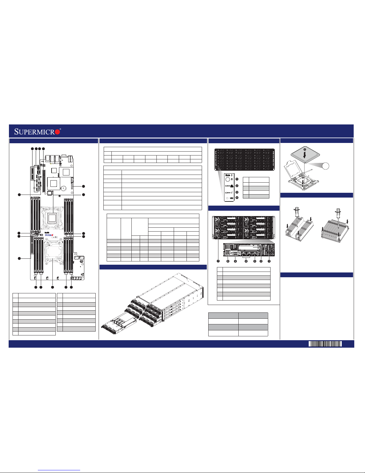
Board Layout
SuperServer F618R2-RC0+/RC0PT+ Quick Reference Guide
CPU Installation
Front View & Interface
Heatsink Installation
1. Place the heatsink on top of the installed CPU.
2. Align the four screws to the socket.
3. Holding the heatsink in place, screw down as shown
(cross pattern, in order: A, C, B, D).
4. Note: Only use 6-8 lb/f of torque; otherwise, hand-tighten
each screw to avoid damaging the CPU.
Memory
Caution
SAFETY INFORMATION
IMPORTANT: See installation instructions and safety warning
before connecting system to power supply.
http://www.supermicro.com/about/policies/safety_information.cfm
WARNING:
To reduce risk of electric shock/damage to equipment,
disconnect power from server by disconnecting all power
cords from electrical outlets.
If any CPU socket empty, install protective plastic CPU cap
CAUTION:
Always be sure all power supplies for this system have
the same power output. If mixed power supplies are
installed, the system will not operate.
For more information go to :
http://www.supermicro.com/support
!
!
!
Rear View
Power Button
LAN LED
Information LED
UID Button
Description
No.
Description
No.
1
2
3
4
1
2
3
4
5
6
7
Micro Low-Profile Expansion Slot
Low-Profile PCI-E Expansion Slot
Dedicated LAN for IPMI
GbE LAN1/LAN2 Ports
VGA Port
USB 0/1 Ports
Power Supply Module
Align CPU to socket;
install CPU straight down
NOTE:
Do not bend pin inside socket
!
1
2
3
4
Node 4
Node 8
Node 3
Node 7
Node 6
Node 5
Node 2
Node 1
Nodes and Corresponding Hard Drives
Screw #B
Screw #C
Screw #A
Node 4
Controls six 2.5" HDDs, D1-D6
Node 8
Controls six 2.5" HDDs, H1-H6
Node 3
Controls six 2.5" HDDs, C1-C6
Node 7
Controls six 2.5" HDDs, G1-G6
Node 2
Controls six 2.5" HDDs, B1-B6
Node 6
Controls six 2.5" HDDs, F1-F6
Node 1
Controls six 2.5" HDDs, A1-A6
Node 5
Controls six 2.5" HDDs, E1-E6
SNK-P0047PSM for CPU2
SNK-P0057P for CPU1
Screw #D
Screw #B
Screw #C
Screw #A
Screw #D
3
4
5
6
7
12
Processors and Memory Module Population for Optimal Performance
Number of
CPUs + DIMMs
CPU and Memory Population Configuration Table
(For memory to work properly, follow the instructions below)
1 CPU & 2 DIMMs
CPU1 & P1-DIMMA1/P1-DIMMB1
1 CPU & 4 DIMMs
1 CPU & 5~8 DIMMs
2 CPUs & 4 DIMMs
2 CPUs & 6 DIMMs
CPU1 & P1-DIMMA1/P1-DIMMB1, P1-DIMMC1/P1-DIMMD1
CPU1 & P1-DIMMA1/P1-DIMMB1, P1-DIMMC1/P1-DIMMD1 + Any memory pairs in P1-DIMMA2/P1-DIMMB2/
P1-DIMMC2/P1-DIMMD2 slots
CPU1 + CPU2 & P1-DIMMA1/P1-DIMMB1, P2-DIMME1/P2-DIMMF1
CPU1 + CPU2 & P1-DIMMA1/P1-DIMMB1/P1-DIMMC1/P1-DIMMD1, P2-DIMME1/P2-DIMMF1
2 CPUs & 8 DIMMs
2 CPUs & 16 DIMMs
CPU1 + CPU2 & P1-DIMMA1/P1-DIMMB1/P1-DIMMC1/P1-DIMMD1, P2-DIMME1/P2-DIMMF1/P2-DIMMG1/P2-DIMMH1
CPU1 + CPU2 & P1-DIMMA1/P1-DIMMB1/P1-DIMMC1/P1-DIMMD1, P2-DIMME1/P2-DIMMF1/P2-DIMMG1/P2-DIMMH1,
P1-DIMMA2/P1-DIMMB2/P1-DIMMC2/P1-DIMMD2, P2-DIMME2/P2-DIMMF2/P2-DIMMG2/P2-DIMMH2
Processors and their Corresponding Memory Modules
CPU#
Corresponding DIMM Modules
CPU 1
P1-DIMMA1
CPU 2 P2-DIMME1
P1-DIMMB1
P2-DIMMF1
P1-DIMMD1
P2-DIMMH1
P1-DIMMA2
P2-DIMME2
P1-DIMMB2
P2-DIMMF2
P1-DIMMD2
P2-DIMMH2
P1-DIMMC2
P2-DIMMG2
P1-DIMMC1
P2-DIMMG1
Description
No.
10
11
12
13
14
15
16
17
CPU2 Socket
P2-DIMMH1 (Blue Slot) / DIMMH2
P2-DIMMG1 (Blue Slot) / DIMMG2
CPU1 SXB2 PCI-E 3.0 x8 Slot
P1-DIMMB1
(Blue Slot) / DIMMB2
P1-DIMMA1 (Blue Slot) / DIMMA2
JSD2: Disk-On-Module power
connector
Description
No.
1
2
3
4
5
6
7
8
9
CPU1 MLP PCI-E 3.0 x8
I-SATA0~5: Supported by Intel PCH
S-SATA0~3: Supported by Intel SCU2
CPU1_SXB_PCI-E 3.0 x16
JTPM1: Trusted Platform Module Header
CPU1 Socket
P1-DIMMC1 (Blue Slot) / DIMMC2
P1-DIMMD1 (Blue Slot) / DIMMD2
P2-DIMME1 (Blue Slot) / DIMME2
X10DRFR-N
JVRM1
JTPM1
JSD1
JSD2
FAN3
FAN1
FAN2
JBT1
T-SGPIO1
T-SGPIO2
LE2
LE3
JBAT1
CPU2
I-SATA0
I-SATA1
I-SATA3
I-SATA4
S-SATA3
S-SATA2
LAN2
LAN1
COM1
USB1(3.0)
USB0(3.0)
CPU1 SXB1 PCI-E 3.0 X16
CPU1 MLP PCI-E 3.0 X8
CPU1 SXB2 PCI-E 3.0 X8
P2-DIMME1
P2-DIMME2
P2-DIMMF1
P2-DIMMF2
P2-DIMMH2
P2-DIMMH1
P2-DIMMG2
P2-DIMMG1
P1-DIMMA1
P1-DIMMA2
P1-DIMMB1
P1-DIMMB2
P1-DIMMD2
P1-DIMMD1
P1-DIMMC2
P1-DIMMC1
POWER BUTTON
I-SATA5
BIOS
VGA
S-SATA1
S-SATA0
PCH
LAN
CTRL
I-SATA2
1
JVRM2
Battery
123
4
5
6
CPU1
7
8
1213
11
910
14
16
17
15
P2-DIMMF1 (Blue Slot) / DIMMF2
2 CPUs & 9~16 DIMMs
CPU1 + CPU2 & P1-DIMMA1/P1-DIMMB1/P1-DIMMC1/P1-DIMMD1, P2-DIMME1/P2-DIMMF1/P2-DIMMG1/P2-DIMMH1
+ Any memory pair in P1, P2 DIMM slots
Rev. 1.0a
Populating RDIMM/LRDIMM DDR4 Memory Modules
Type
Ranks
Per DIMM
and Data
Width
DIMM Capacity
(GB)
Speed (MT/s); Voltage (V); Slots per Channel (SPC) and
DIMMs per Channel (DPC)
2 Slots per Channel
1 DPC 2 DPC
E5-2600 V3 E5-2600 V4 E5-2600 V3 E5-2600 V4
4 GB 8 GB 1.2 V 1.2 V 1.2 V 1.2 V
RDIMM SRx4 8 GB 16 GB 2133 2400 1866 2133
RDIMM SRx8 4 GB 8 GB 2133 2400 1866 2133
RDIMM DRx8 8 GB 16 GB 2133 2400 1866 2133
RDIMM DRx4 16 GB 32 GB 2133 2400 1866 2133
LRDIMM QRx4 32 GB 64 GB 2133 2400 2133 2400
LRDIMM 3DS 8Rx4 64 GB 128 GB 2133 2400 2133 2400
 Loading...