

Supermicro SuperServer 6027TR-DTRF+, SuperServer 6027TR-D70RF+, SuperServer 6027TR-D71RF+ User Manual
®
SUPER
SUPERSERVER
Revision 1.0
SUPERSERVER
6027TR-DTRF+
6027TR-D70RF+
6027TR-D71RF+

The information in this User’s Manual has been carefully reviewed and is believed to be accurate.
The vendor assumes no responsibility for any inaccuracies that may be contained in this document,
makes no commitment to update or to keep current the information in this manual, or to notify any
person or organization of the updates. Please Note: For the most up-to-date version of this
manual, please see our web site at
www.supermicro.com.
Super Micro Computer, Inc. ("Supermicro") reserves the right to make changes to the product
described in this manual at any time and without notice. This product, including software and
documentation, is the property of Supermicro and/or its licensors, and is supplied only under a
license. Any use or reproduction of this product is not allowed, except as expressly permitted by
the terms of said license.
IN NO EVENT WILL SUPERMICRO BE LIABLE FOR DIRECT, INDIRECT, SPECIAL, INCIDENTAL,
SPECULATIVE OR CONSEQUENTIAL DAMAGES ARISING FROM THE USE OR INABILITY TO
USE THIS PRODUCT OR DOCUMENTATION, EVEN IF ADVISED OF THE POSSIBILITY OF
SUCH DAMAGES. IN PARTICULAR, SUPERMICRO SHALL NOT HAVE LIABILITY FOR ANY
HARDWARE, SOFTW ARE, OR DA TA ST ORED OR USED WITH THE PRODUCT, INCLUDING THE
COSTS OF REPAIRING, REPLACING, INTEGRATING, INSTALLING OR RECOVERING SUCH
HARDWARE, SOFTWARE, OR DATA.
Any disputes arising between manufacturer and customer shall be governed by the laws of Santa
Clara County in the State of California, USA. The State of California, County of Santa Clara shall
be the exclusive venue for the resolution of any such disputes. Super Micro's total liability for all
claims will not exceed the price paid for the hardware product.
FCC Statement: This equipment has been tested and found to comply with the limits for a Class
A digital device pursuant to Part 15 of the FCC Rules. These limits are designed to provide
reasonable protection against harmful interference when the equipment is operated in a commercial
environment. This equipment generates, uses, and can radiate radio frequency energy and, if not
installed and used in accordance with the manufacturer’s instruction manual, may cause harmful
interference with radio communications. Operation of this equipment in a residential area is likely
to cause harmful interference, in which case you will be required to correct the interference at your
own expense.
California Best Management Practices Regulations for Perchlorate Materials: This Perchlorate
warning applies only to products containing CR (Manganese Dioxide) Lithium coin cells. “Perchlorate
Material-special handling may apply. See
www.dtsc.ca.gov/hazardouswaste/perchlorate”
WARNING: Handling of lead solder materials used in this
product may expose you to lead, a chemical known to
the State of California to cause birth defects and other
reproductive harm.
Manual Revision 1.0
Release Date: December 26, 2012
Unless you request and receive written permission from Super Micro Computer, Inc., you may not
copy any part of this document.
Information in this document is subject to change without notice. Other products and companies
referred to herein are trademarks or registered trademarks of their respective companies or mark
holders.
Copyright © 2012 by Super Micro Computer, Inc.
All rights reserved.
Printed in the United States of America
iii
Preface
Preface
About This Manual
This manual is written for professional system integrators and PC technicians.
It provides information for the installation and use of the SuperServer
6027TR-DTRF+/D70RF+/D71RF+. Installation and maintainance should be
performed by experienced technicians only.
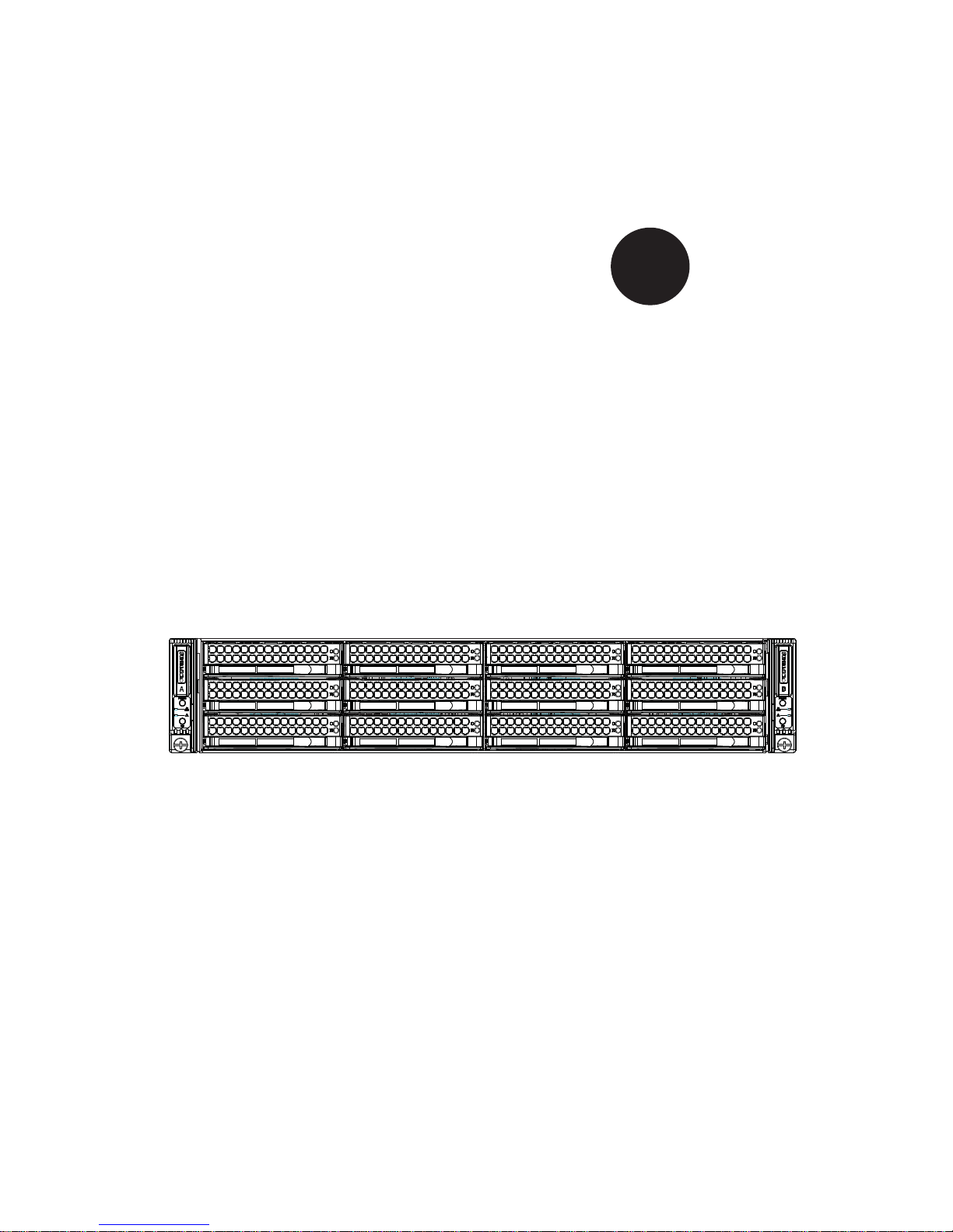
The SuperServer 6027TR-DTRF+/D70RF+/D71RF+ are all high-end servers
based on the SC827HD-R1K28MB 2U rackmount chassis and the dual processor
X9DRT-HF+ serverboard. All models have an IPMI LAN port and two serverboard
nodes with six hot-swap Hard Disk Drives (HDD) each per node.
Each of the various models of the SuperServer 6027TR-DTRF+/D70RF+/D71RF+
servers contains the same X9DRT-HF+ serverboard. The systems differ in the type
of RAID chip system mounted in the system on their HDD adapter cards, as listed
in the table below:
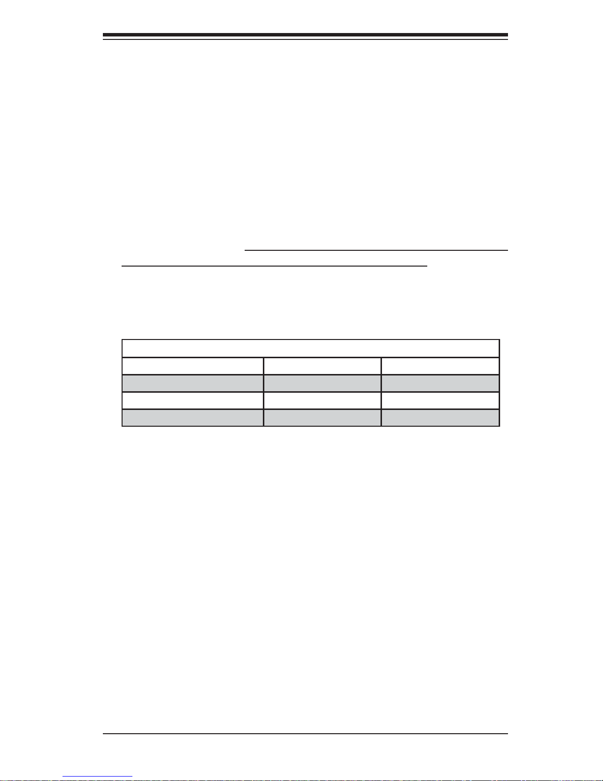
SUPERSERVER 6027TR-DTRF+/D70RF+/D71RF+ Model Variations
Server Model SAS RAID Chip System HDD Adapter Card
6027TR-DTRF+
No SAS BPN-ADPX9-6SATA-O-P
6027TR-D70RF+
LSI SAS2008 BPN-ADP-SAS2-L6I-O-P
6027TR-D71RF+
LSI SAS2108 BPN-ADP-SAS2-H6IR-O-P
Manual Organization
Chapter 1: Introduction
The fi rst chapter provides a checklist of the main components included with the
server system and describes the main features of the X9DRT-HF+ serverboard and
the SC827HD-R1K28MB chassis.
Chapter 2: Server Installation
This chapter describes the steps necessary to install the SuperServer
6027TR-DTRF+/D70RF+/D71RF+ into a rack and check out the server confi guration
prior to powering up the system. If your server was ordered without processor and
memory components, this chapter will refer you to the appropriate sections of the
manual for their installation.
Chapter 3: System Interface
Refer here for details on the system interface, which includes the functions and
information provided by the control panel on the chassis as well as other LEDs
located throughout the system.

SUPERSERVER 6027TR-DTRF+/D70RF+/D71RF+ User's Manual
iv
Chapter 4: System Safety
You should thoroughly familiarize yourself with this chapter for a general overview
of safety precautions that should be followed when installing and servicing the
SuperServer 6027TR-DTRF+/D70RF+/D71RF+.
Chapter 5: Advanced Serverboard Setup
Chapter 5 provides detailed information on the X9DRT-HF+ serverboard, including
the locations and functions of connections, headers and jumpers. Refer to
this chapter when adding or removing processors or main memory and when
reconfi guring the serverboard.
Chapter 6: Advanced Chassis Setup
Refer to Chapter 6 for detailed information on the SC827HD-R1K28MB server
chassis. You should follow the procedures given in this chapter when installing,
removing or reconfi guring SATA or peripheral drives and when replacing system
power supply units and cooling fans.
Chapter 7: BIOS
The BIOS chapter includes an introduction to BIOS and provides detailed information
on running the CMOS Setup Utility.
Appendix A: BIOS Error Beep Codes
Appendix B: System Specifi cations

v
SUPERSERVER 6027TR-DTRF+/D70RF+/D71RF+ SUPERSERVER
Notes

vi
Table of Contents
Chapter 1 Introduction
1-1 Overview .........................................................................................................1-1
1-2 Serverboard Features .....................................................................................1-2
Processors ......................................................................................................1-2
Memory ...........................................................................................................1-2
Serial ATA .......................................................................................................1-2
SAS .................................................................................................................1-3
PCI Expansion Slots ....................................................................................... 1-3
Onboard Controllers/Ports .............................................................................. 1-3
Graphics Controller ......................................................................................... 1-3
Other Features ................................................................................................1-3
1-3 Server Chassis Features ................................................................................ 1-4
System Power .................................................................................................1-4
SAS/SATA Subsystem .....................................................................................1-4
Front Control Panel ......................................................................................... 1-4
I/O Ports ..........................................................................................................1-4
Cooling System ...............................................................................................1-5
Air Shrouds ..................................................................................................... 1-5
Mounting Rails ................................................................................................ 1-5
1-4 Advanced Power Management ....................................................................... 1-5
Intel® Intelligent Power Node Manager (NM) .................................................1-5
Manageability Engine (ME) ............................................................................. 1-5
1-5 Contacting Supermicro ....................................................................................1-7
1-6 2U Twin: System Notes ...................................................................................1-8
Nodes ..............................................................................................................1-8
System Power .................................................................................................1-8
SAS/SATA Backplane/Drives .......................................................................... 1-8
Chapter 2 Server Installation
2-1 Overview .........................................................................................................2-1
2-2 Unpacking the System ....................................................................................2-1
2-3 Preparing for Setup ......................................................................................... 2-1
Choosing a Setup Location .............................................................................2-2
2-4 Warnings and Precautions .............................................................................. 2-2
Rack Precautions ............................................................................................2-2
Server Precautions ..........................................................................................2-2
Rack Mounting Considerations .......................................................................2-3
SUPERSERVER 6027TR-DTRF+/D70RF+/D71RF+ User's Manual

vii
Ambient Operating Temperature ................................................................ 2-3
Reduced Airfl ow ......................................................................................... 2-3
Mechanical Loading ................................................................................... 2-3
Circuit Overloading ..................................................................................... 2-3
Reliable Ground ......................................................................................... 2-3
2-5 Installing the System into a Rack ................................................................... 2-4
Separating the Sections of the Rack Rails ..................................................... 2-4
Installing the Inner Rail Extension .................................................................. 2-5
Outer Rack Rails ............................................................................................. 2-6
2-6 Checking the Serverboard Setup ....................................................................2-7
2-7 Checking the Drive Bay Setup ........................................................................2-8
Chapter 3 System Interface
3-1 Overview .........................................................................................................3-1
3-2 Control Panel Button ....................................................................................... 3-2
3-3 Control Panel LEDs ........................................................................................ 3-2
3-4 Drive Carrier LEDs .......................................................................................... 3-3
SATA Drives ....................................................................................................3-3
Chapter 4 Standardized Warning Statements for AC Systems
4-1 About Standardized Warning Statements ....................................................... 4-1
Warning Defi nition ........................................................................................... 4-1
Installation Instructions ....................................................................................4-4
Circuit Breaker ................................................................................................ 4-5
Power Disconnection Warning ........................................................................ 4-6
Equipment Installation ..................................................................................... 4-8
Restricted Area ................................................................................................ 4-9
Battery Handling ............................................................................................4-10
Redundant Power Supplies .......................................................................... 4-12
Backplane Voltage ........................................................................................ 4-13
Comply with Local and National Electrical Codes ........................................4-14
Product Disposal ...........................................................................................4-15
Hot Swap Fan Warning .................................................................................4-16
Power Cable and AC Adapter ...................................................................... 4-18
Chapter 5 Advanced Serverboard Setup
5-1 Handling the Serverboard ...............................................................................5-1
Precautions .....................................................................................................5-1
Unpacking .......................................................................................................5-1
5-2 Connecting Cables .......................................................................................... 5-2
Connecting Data Cables .................................................................................5-2
Table of Contents

viii
5-3 Rear I/O Ports .................................................................................................5-2
5-4 Processor and Heatsink Installation................................................................5-3
Installing a Passive CPU Heatsink ................................................................. 5-7
Removing the Passive Heatsink .....................................................................5-7
5-5 Installing Memory ............................................................................................5-8
Memory Support ..............................................................................................5-8
Maximum Memory ...........................................................................................5-8
DIMM Module Population Confi guration .................................................. 5-10
5-6 Adding PCI Expansion Cards ....................................................................... 5-12
5-7 Serverboard Details ...................................................................................... 5-13
5-8 Connector Defi nitions .................................................................................... 5-16
5-9 Jumper Settings ............................................................................................ 5-19
Explanation of Jumpers ................................................................................ 5-19
5-10 Onboard Indicators ........................................................................................5-21
5-11 PCI-Express and Serial ATA Connections .................................................... 5-23
5-12 Installing Drivers ............................................................................................5-24
Supero Doctor III ........................................................................................... 5-25
5-13 Serverboard Battery ......................................................................................5-27
Chapter 6 Advanced Chassis Setup
6-1 Static-Sensitive Devices ..................................................................................6-1
Precautions .....................................................................................................6-1
Unpacking .......................................................................................................6-1
6-2 Control Panel ..................................................................................................6-2
6-3 Chassis Cover ................................................................................................. 6-3
6-4 Installing the Air Shrouds ................................................................................ 6-4
Air Shrouds ..................................................................................................... 6-4
6-5 Checking the Airfl ow .......................................................................................6-5
6-6 System Fans ................................................................................................... 6-5
Optional Fan Confi gurations ...........................................................................6-5
6-7 Removing and Installing the Backplane ..........................................................6-8
Removing the Backplane ................................................................................6-8
Installing the Backplane ................................................................................6-10
6-8 Installing the Serverboard ..............................................................................6-11
I/O Shield .......................................................................................................6-11
Compatible Serverboards ..............................................................................6-11
Permanent and Optional Standoffs ................................................................6-11
6-9 Node Installation/Removal ............................................................................6-13
6-10 Installing and Replacing the MicroLP Card ..................................................6-15
SUPERSERVER 6027TR-DTRF+/D70RF+/D71RF+ User's Manual

6-11 Installing and Removing Hard Drives ........................................................... 6-16
6-12 Power Supply ................................................................................................6-19
Power Supply Replacement ..........................................................................6-19
Power Supply Replacement ..........................................................................6-19
Chapter 7 BIOS
7-1 Introduction ......................................................................................................7-1
Starting BIOS Setup Utility ..............................................................................7-1
How To Change the Confi guration Data .........................................................7-1
Starting the Setup Utility ................................................................................. 7-2
7-2 Main Setup ......................................................................................................7-2
7-3 Advanced Settings Menu ................................................................................7-3
7-4 Event Logs .................................................................................................... 7-26
7-5 IPMI ............................................................................................................... 7-28
7-6 Boot ...............................................................................................................7-30
7-7 Security .........................................................................................................7-31
7-8 Save & Exit ................................................................................................... 7-32
Appendix A BIOS Error Beep Codes
Appendix B System Specifi cations
ix
Table of Contents

x
Notes
SUPERSERVER 6027TR-DTRF+/D70RF+/D71RF+ User's Manual

Chapter 1
Introduction
1-1 Overview
The SuperServer 6027TR-DTRF+/D70RF+/D71RF+ is a high-end server comprised
of two main subsystems: the SC827HD-R1K28MB 2U server chassis and the
X9DRT-HF+ dual processor serverboard in two hot-swap nodes. Please refer to
our web site for information on operating systems that have been certifi ed for use
with the system (www.supermicro.com).
In addition to the serverboard and chassis, various hardware components have
been included with the 6027TR-DTRF+/D70RF+/D71RF+ server, as listed below:
• Heat Sinks
Four (4) 2U Passive CPU heat sinks w/narrow ILM (SNK-P0048PS)
• Two (2) Plastic air shrouds (MCP-310-82718-0B)
• Four (4) 80x80x38mm cooling fans (FAN-0129L4)
• SATA/SAS Backplane
One (1) SAS Backplane for 12 3.5" HDD (BPN-SAS-827HD)
Twelve (12) hot-swap 3.5" HDD trays (MCP-220-00075-0B)
6027TR-DTRF+ Only:
Four (4) 29-cm 30AWG SATA cables (CBL-0483L)
Two (2) 6-port SATA adapter cards (BPN-ADPX9-6SATA-O-P)
6027TR-D70RF+ Only:
Two (2) SAS2 LSI2008 HD adapter cards (BPN-ADP-SAS2-L6I-O-P)
6027TR-D71RF+ Only:
Two (2) SAS2 LSI2108 HD adapter cards (BPN-ADP-SAS2-H6IR-O-P)
• One (1) Rails set (MCP-290-00053-0N)
Note: a complete list of safety warnings is provided on the Supermicro web site at
http://www.supermicro.com/about/policies/safety_information.cfm
Chapter 1: Introduction
1-1

1-2
SUPERSERVER 6027TR-DTRF+/D70RF+/D71RF+ User's Manual
1-2 Serverboard Features
At the heart of the 6027TR-DTRF+/D70RF+/D71RF+ server
lies the X9DRT-HF+, a dual processor serverboard based on the Intel®
C602 chipset and designed to provide maximum performance. Two of these
serverboards can be mounted in the SC827HD-R1K28MB chassis.
The sections below cover the main features of the X9DRT-HF+ serverboard (see
Figure 1-1 for a block diagram of the chipset).
Processors
The X9DRT-HF+ supports single or dual Intel Xeon® E5-2600 series processors
(Socket R LGA 2011). Please refer to the serverboard description pages on our
web site for a complete listing of supported processors (www.supermicro.com).
Memory
The X9DRT-HF+ has sixteen (16) DIMM slots supporting up to 512 GB of
DDR3-1600/1333/1066/800 MHz speed registered ECC SDRAM in up to
512 MB, 1 GB, 2 GB, 4 GB, 8 GB, 16 GB or 32 GB sizes at 1.35V or 1.5V
voltages. See Chapter 5 for details.
Note: Check the Supermicro website (www.supermicro.com) for the latest memory
support information.
Serial ATA
A Serial ATA controller is integrated into each node's C602 chipset to provide up to
a six 6-port SATA subsystem. Two SATA 3 ports are available on the serverboard
(SATA 0/1) and a six port BPN-ADPX9-6SATA-O-P adapter card is mounted for
each serverboard node. RAID 0, 1, 5 and 10 are supported. The SATA drives are
hot-swappable units.
Note: The operati ng system yo u use must h ave R AID su ppor t to e nable t he hotswap capability and RAI D function of the SATA drives.

1-3
Chapter 1: Introduction
SAS
An LSI® SAS2008 or SAS2108 SAS2 controller is integrated into the installed
BPN-ADP-SAS2-L6I-O-P (6027TR-D70RF+) or BPN-ADP-SAS2-H6IR-O-P
(6027TR-D71RF+) adapter cards to provide an eight port 6 Gb/s SAS2 (Serial
Attached SCSI) subsystem for each node. The system has either RAID 0, 1 and 10
support (RAID 5 with optional AOC-SAS2-RAID5-KEY) for the SuperServer
6027TR-D70RF+ or RAID 0, 1, 5, 6, 10, and 50 support for the SuperServer
6027TR-D71RF+ server. The SAS drives are hot-swappable units.
Note: The operating system you use must have RAID support to enable the
hotswap c apabil ity an d R AID fu ncti on of the SA S drive s.
PCI Expansion Slots
The SuperServer 6027TR-DTRF+/D70RF+/D71RF+ has for each node one (1)
PCI-E 3.0 x8 Slot for SMC-Proprietary Micro LP Card (CPU1 Slot2) and one (1)
PCI-E 3.0 x8 Slot for SMC-Proprietary Daughter (Add-On) Card (CPU1 Slot1).
Onboard Controllers/Ports
The color-coded I/O ports include a VGA (monitor) port, two USB 2.0 ports (an
additional internal USB header and one Type A USB connector are included on the
serverboard), an IPMI 2.0 dedicated LAN port and two Ethernet ports.
Note: For IPMI Confi guration Instructions, please refer to the Embedded BMC
Confi guration User's Guide available @ http://www.supermicro.com/support/
manuals/ for IPMI 2.0 system.
Graphics Controller
The X9DRT-HF+ features an integrated Matrox® G200eW Video Controller.
Other Features
Other onboard features that promote system health include onboard voltage
monitors, a chassis intrusion header, auto-switching voltage regulators, chassis and
CPU overheat sensors, virus protection, node manager software and BIOS rescue.

1-4
SUPERSERVER 6027TR-DTRF+/D70RF+/D71RF+ User's Manual
1-3 Server Chassis Features
The following is a general outline of the main features of the SC827 server chassis.
System Power
Each SC827 chassis model includes a high-effi ciency 80-plus Platinum certifi ed
power supply, rated at 1280 Watts plus one redundant backup power supply.
In the unlikely event your power supply fails, replacement is simple and can be
accomplished without tools.
SAS/SATA Subsystem
The SC827 supports up to twelve (12) 3.5" hot-swap SAS/SATA drives in trays
(6 for each node). These drives are hot-swappable units and are connected to a
backplane that provides power and control.
Note: The operating system you use must have RAID support to enable the hotswap capability of the drives.
Front Control Panel
SC827HD-R1K28MB chassis includes two front panels on the handles of the
chassis which control each of the systems. Each control panel on the SuperServer
6027TR-DTRF+/D70RF+/D71RF+ provides you with system monitoring and control
for one server node. LEDs indicate system power, HDD activity, network activity,
system overheat and power supply failure. A main power button and a system reset
button are also included.
I/O Ports
The SC827 is an propriertary form factor chassis designed to be used in a 2U
rackmount confi guration. The SC827 chassis provides a low-profi le add-on card
slot, a COM port, a VGA port, two USB 2.0 ports, one IPMI Ethernet port and two
Ethernet ports per node.

1-5
Chapter 1: Introduction
Cooling System
The SC827 chassis accepts four system fans powered from either backpane or
the serverboards. If not powered from the backpane, the SC827HD-R1K28MB
model chassis powers four fans from two serverboards, so that when one of the
serverboard drawers is removed, the other serverboards will continue running all
fans.
Air Shrouds
The SC827 chassis includes two mylar air shrouds that direct the airfl ow where
cooling is needed on each serverboard. Always use the air shroud included with
your chassis on each serverboard.
Mounting Rails
The SC827 includes a set of quick-release rails, and can be placed in a rack for
secure storage and use. To setup your rack, follow the step-by-step instructions
included in this manual.
1-4 Advanced Power Management
Intel® Intelligent Power Node Manager (NM)
The Intel® Intelligent Power Node Manager (IPNM) provides your system with
real-time thermal control and power management for maximum energy effi ciency.
Although IPNM Specifi cation Version 1.5 is supported by the BMC (Baseboard
Management Controller), your system must also have IPNM-compatible
Manageability Engine (ME) fi rmware installed to use this feature.
Manageability Engine (ME)
The Manageability Engine, which is an ARC controller embedded in the IOH (I/O
Hub), provides Server Platform Services (SPS) to your system. The services
provided by SPS are different from those proveded by the ME on client platforms.
1-6
SUPERSERVER 6027TR-DTRF+/D70RF+/D71RF+ User's Manual
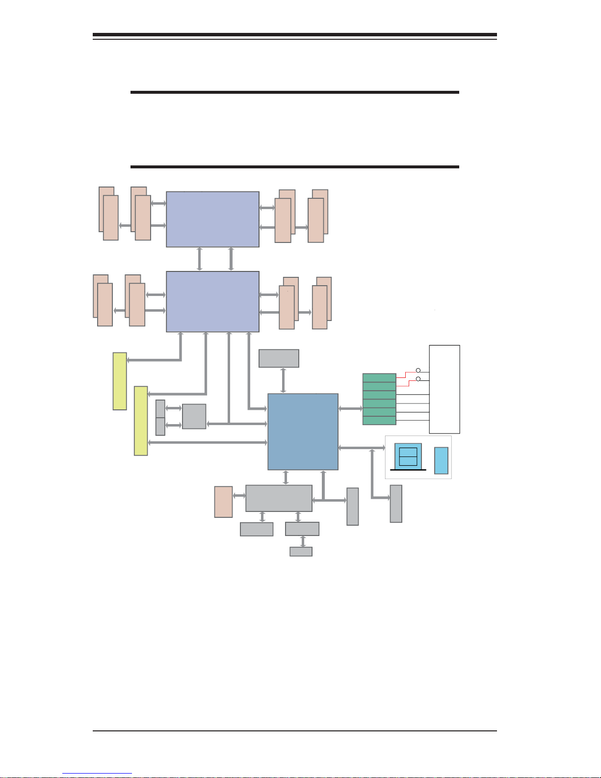
Figure 1-1. Intel C602 Chipset:
System Block Diagram
Note: This is a general block diagram and may not exactly repre-
sent the features on your serverboard. See the previous pages for
the actual specifi cations of your serverboard. This block diagram is
intended for your reference only.
#2
#2
#2
#2
#2
#2
#2
#2
PROCESSOR
SANDYBRIDGE
PROCESSOR
SANDYBRIDGE
QPI
DDR3 DIMM
DDR3 DIMM
DDR3 DIMM
DDR3 DIMM
#1
G
SSB
PATSBURG
PEG0
DMI
PEG1_1
PEG1_8
PCI-32bit
USB
LAN
I350
2 ports
AT25321
LPC
CPU FRONT
FAN Side
CPU REAR
(I/O Side)
USB
REAR
HDR 2X5
0,1
TPM Header
USB Type-A
2,3
U7C1
U6H1
H
F
E
Socket 0
Socket 1
#1
P0
P0
P1
P1
PE3 PE2 PE1 DMI
PE3 PE2 PE1 DMI
Gen3
x8
x4
VGA BMC
WPCM450
DDR2
PHY1
LAN
RTL8201F
SPI
SATA
Gen2
PCI-E x8 MicroLP SLOT
x4
RJ45 RJ45
Gen3
x8
Gen3
x8
PCI-E x8 in x4 SLOT
x8
x1
x8(0..7)
HOTSWAP INTERFACE
SATA2 #5
SATA2 #4
SATA2 #3
SATA2 #2
SATA3 #1
SATA3 #0
PORT6
PORT5
PORT4
PORT3
PORT2
PORT1
6/3/1.5
QPI
VGA CONN
DDR3 DIMM
DDR3 DIMM
#1
C
#1
D
DDR3 DIMM
DDR3 DIMM
A
B
#1
#1
#1
#1
J1
J2

1-7
Chapter 1: Introduction
1-5 Contacting Supermicro
Headquarters
Address: Super Micro Computer, Inc.
980 Rock Ave.
San Jose, CA 95131 U.S.A.
Tel: +1 (408) 503-8000
Fax: +1 (408) 503-8008
Email: marketing@supermicro.com (General Information)
support@supermicro.com (Technical Support)
Web Site:
www.supermicro.com
Europe
Address: Super Micro Computer B.V.
Het Sterrenbeeld 28, 5215 ML
's-Hertogenbosch, The Netherlands
Tel: +31 (0) 73-6400390
Fax: +31 (0) 73-6416525
Email: sales@supermicro.nl (General Information)
support@supermicro.nl (Technical Support)
rma@supermicro.nl (Customer Support)
Asia-Pacifi c
Address: Super Micro Computer, Inc.
4F, No. 232-1, Liancheng Rd.
Chung-Ho Dist., New Taipei City 235
Taiwan
Tel: +886-(2) 8226-3990
Fax: +886-(2) 8226-3991
Web Site:
www.supermicro.com.tw
Technical Support:
Email: support@supermicro.com.tw
Tel: 886-2-8228-1366, ext.132 or 139

1-8
SUPERSERVER 6027TR-DTRF+/D70RF+/D71RF+ User's Manual
1-6 2U Twin: System Notes
As a 2U Twin2 confi guration, the SuperServer 6027TR-DTRF+/D70RF+/D71RF+ is
a unique server system. With two system boards incorporated into a single chassis
acting as two separate nodes, there are several points you should keep in mind.
Nodes
Each of the two serverboards act as a separate node in the system. As independant
nodes, each may be powered off and on without affecting the others. In addition,
each node is a hot-swappable unit that may be removed from the rear of the chassis.
The nodes are connected to the server backplane by means of an adapter card.
Note: A guide pin is located between the upper and lower nodes on the inner chassis
wall. This guide pin also acts as a “stop” when a node is fully installed. If too much
force is used when inserting a node this pin may break off. Take care to slowly slide
a node in until you hear the “click” of the locking tab seating itself.
System Power
Dual 1280 Watt redundant power supplies are used to provide the power for all
two serverboards. Each serverboard however, can be shut down independently of
the other with the power button on its own control panel.
SAS/SATA Backplane/Drives
As a system, the SuperServer 6027TR-DTRF+/D70RF+/D71RF+ supports the use
of twelve SAS/SATA drives. A single SAS/SATA backplane works to apply systembased control for power and fan speed functions, yet at the same time logically
connects a set of three SAS/SATA drives to each serverboard. Consequently, RAID
setup is limited to a three-drive scheme (RAID cannot be spread across all twelve
drives). See the Drive Bay Installation/Removal section in Chapter 6 for the logical
hard drive and node confi guration.
Chapter 2: Server Installation
2-1
Chapter 2
Server Installation
2-1 Overview
This chapter provides a quick setup checklist to get your SuperServer
6027TR-DTRF+/D70RF+/D71RF+ up and running. Following these steps in the
order given should enable you to have the system operational within a minimum
amount of time. This quick setup assumes that your system has come to you with the
processors and memory preinstalled. If your system is not already fully integrated
with a serverboard, processors, system memory etc., please turn to the chapter or
section noted in each step for details on installing specifi c components.
2-2 Unpacking the System
Y ou should inspect the box the SuperServer 6027TR-DTRF+/D70RF+/D71RF+ was
shipped in and note if it was damaged in any way. If the server itself shows damage
you should fi le a damage claim with the carrier who delivered it.
Decide on a suitable location for the rack unit that will hold the SuperServer
6027TR-DTRF+/D70RF+/D71RF+. It should be situated in a clean, dust-free area
that is well ventilated. Avoid areas where heat, electrical noise and electromagnetic
fi elds are generated. You will also need it placed near a grounded power outlet.
Read the Rack and Server Precautions in the next section.
2-3 Preparing for Setup
The box the SuperServer 6027TR-DTRF+/D70RF+/D71RF+ was shipped in should
include two sets of rail assemblies, two rail mounting brackets and the mounting
screws you will need to install the system into the rack. Follow the steps in the
order given to complete the installation process in a minimum amount of time.
Please read this section in its entirety before you begin the installation procedure
outlined in the sections that follow.

2-2
SUPERSERVER 6027TR-DTRF+/D70RF+/D71RF+ User's Manual
Choosing a Setup Location
• Leave enough clearance in front of the rack to enable you to open the front door
completely (~25 inches) and approximately 30 inches of clearance in the back
of the rack to allow for suffi cient airfl ow and ease in servicing.
• This product is for installation only in a Restricted Access Location (dedicated
equipment rooms, service closets and the like).
• This product is not suitable for use with visual display work place devices
acccording to §2 of the the German Ordinance for Work with Visual Display Units.
2-4 Warnings and Precautions
Rack Precautions
• Ensure that the leveling jacks on the bottom of the rack are fully extended to
the fl oor with the full weight of the rack resting on them.
• In single rack installation, stabilizers should be attached to the rack. In multiple
rack installations, the racks should be coupled together.
• Always make sure the rack is stable before extending a component from the
rack.
• You should extend only one component at a time - extending two or more
simultaneously may cause the rack to become unstable.
Server Precautions
• Review the electrical and general safety precautions in Chapter 4.
• Determine the placement of each component in the rack before you install the
rails.
• Install the heaviest server components on the bottom of the rack fi rst, and then
work up.
• Use a regulating uninterruptible power supply (UPS) to protect the server from
power surges, voltage spikes and to keep your system operating in case of a
power failure.
• Allow any hot plug drives and power supply modules to cool before touching
them.
• Always keep the rack's front door and all panels and components on the servers
closed when not servicing to maintain proper cooling.
Chapter 2: Server Installation
2-3
Rack Mounting Considerations
Ambient Operating Temperature
If installed in a closed or multi-unit rack assembly, the ambient operating
temperature of the rack environment may be greater than the ambient temperature
of the room. Therefore, consideration should be given to installing the equipment
in an environment compatible with the manufacturer’s maximum rated ambient
temperature (Tmra).
Reduced Airfl ow
Equipment should be mounted into a rack so that the amount of airfl ow required
for safe operation is not compromised.
Mechanical Loading
Equipment should be mounted into a rack so that a hazardous condition does not
arise due to uneven mechanical loading.
Circuit Overloading
Consideration should be given to the connection of the equipment to the power
supply circuitry and the effect that any possible overloading of circuits might have
on overcurrent protection and power supply wiring. Appropriate consideration of
equipment nameplate ratings should be used when addressing this concern.
Reliable Ground
A reliable ground must be maintained at all times. To ensure this, the rack
itself should be grounded. Particular attention should be given to power supply
connections other than the direct connections to the branch circuit (i.e. the use of
power strips, etc.).
Warning! To prevent bodily injury when mounting or servicing this unit in a
rack, you must take special precautions to ensure that the system remains
stable. The following guidelines are provided to ensure your safety:
• This unit should be mounted at the bottom of the rack if it is the only unit in
the rack.
• When mounting this unit in a partially fi lled rack, load the rack from the bottom
to the top with the heaviest component at the bottom of the rack.
• If the rack is provided with stabilizing devices, install the stabilizers before
mounting or servicing the unit in the rack.
2-4
SUPERSERVER 6027TR-DTRF+/D70RF+/D71RF+ User's Manual
2-5 Installing the System into a Rack
This section provides information on installing the SC827 chassis into a rack unit
with the quick-release rails provided. There are a variety of rack units on the market,
which may mean the assembly procedure will differ slightly. You should also refer to
the installation instructions that came with the rack unit you are using.
NOTE: This rail will fi t a rack between 26" and 33.5" deep.
Separating the Sections of the Rack Rails
The chassis package includes two rail assemblies in the rack mounting kit. Each
assembly consists of two sections: an inner fi xed chassis rail that secures directly to
the server chassis and an outer fi xed rack rail that secures directly to the rack itself.
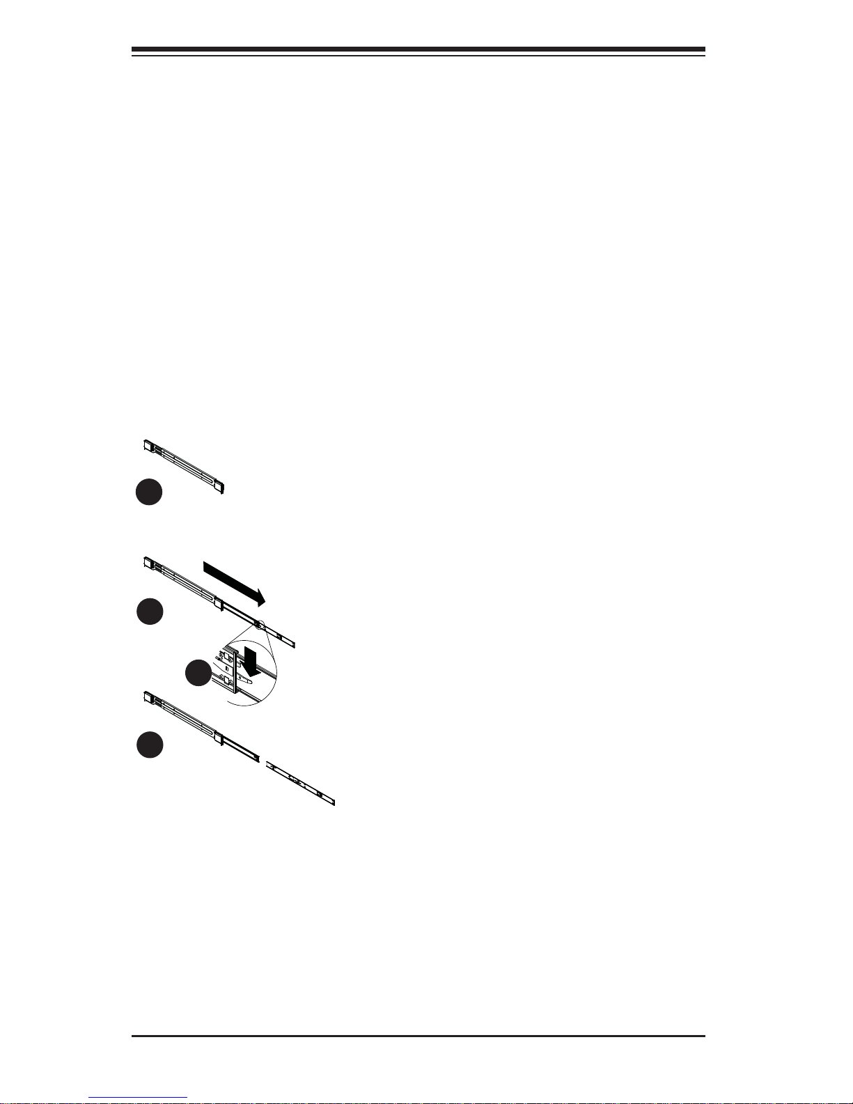
Figure 2-1: Separating the Rack Rails
Separating the Inner and Outer
Rails
1. Locate the rail assembly in the
chassis packaging.
2. Extend the rail assembly by
pulling it outward.
3. Press the quick-release tab.
4. Separate the inner rail
extension from the outer rail
assembly.
1
1
1
2
1
4
1
3
Rail Assembly
Extending the Rails
Quick-Release Tab
Separating
the Inner Rail
Extension
Chapter 2: Server Installation
2-5
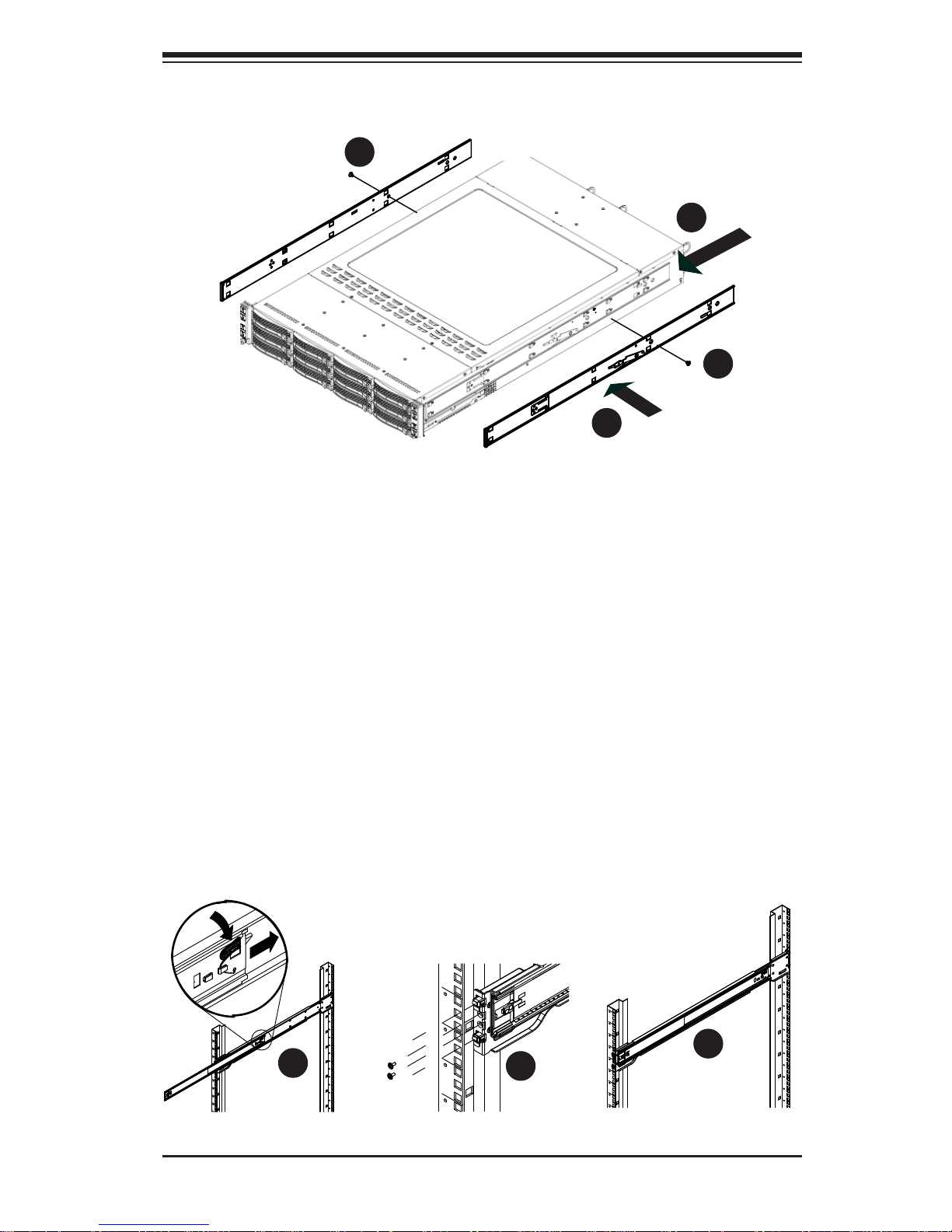
Figure 2-2: Installing the Inner Rail Extensions
Installing the Inner Rail Extension
The SC827 chassis includes a set of inner rails in two sections: inner rails and inner
rail extensions. The inner rails are pre-attached to the chassis, and do not interfere
with normal use of the chassis if you decide not to use a server rack. The inner rail
extension is attached to the inner rail to mount the chassis in the rack.
Installing the Inner Rails
1. Place the inner rail extensions on the side of the chassis aligning the hooks
of the chassis with the rail extension holes. Make sure the extension faces
"outward" just like the pre-attached inner rail.
2. Slide the extension toward the front of the chassis.
3. Secure the chassis with 2 screws as illustrated. Repeat steps for the other
inner rail extension.
1
1
1
2
1
3
1
3
Figure 2-3. Assembling the Outer Rails
1
1
1
2
1
3
2-6
SUPERSERVER 6027TR-DTRF+/D70RF+/D71RF+ User's Manual
Outer Rack Rails
Outer rails attach to the rack and hold the chassis in place. The outer rails for the
SC827 chassis extend between 30 inches and 33 inches.
Installing the Outer Rails to the Rack
1. Secure the back end of the outer rail to the rack, using the screws provided.
2. Press the button where the two outer rails are joined to retract the smaller
outer rail.
3. Hang the hooks of the rails onto the rack holes and if desired, use screws to
secure the front of the outer rail onto the rack.
4. Repeat steps 1-3 for the remaining outer rail.
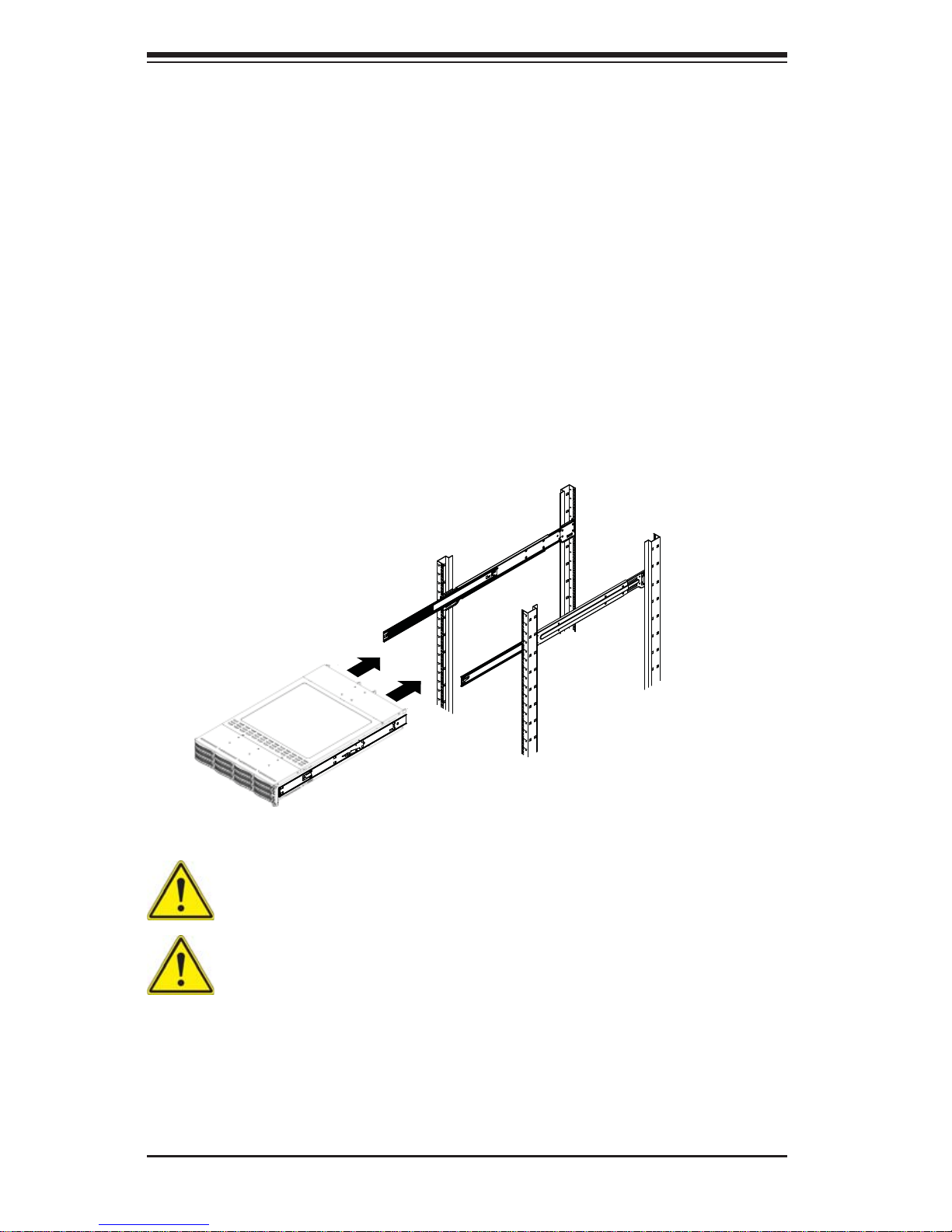
Figure 2-4: Installing the Rack Rails
Stability hazard. The rack stabilizing mechanism must be in place, or the
rack must be bolted to the fl oor before you slide the unit out for servicing.
Failure to stabilize the rack can cause the rack to tip over.
Warning: do not pick up the server with the front handles. They are designed
to pull the system from a rack only.
Note: The fi gure above is for illustration purposes only. Always install servers to
the bottom of the rack fi rst.
Installing the Chassis into a Rack
1. Extend the outer rails as illustrated above.
2. Align the inner rails of the chassis with the outer rails on the rack.

Chapter 2: Server Installation
2-7
3. Slide the inner rails into the outer rails, keeping the pressure even on both
sides. When the chassis has been pushed completely into the rack, it should
click into the locked position.
4. Optional screws may be used to secure the to hold the front of the chassis to
the rack.
2-6 Checking the Serverboard Setup
After you install the SUPERSERVER 6027TR-DTRF+/D70RF+/D71RF+ in the rack,
you will need to open the unit to make sure the serverboard is properly installed
and all the connections have been made.
Accessing the inside of the System
Before operating the server for the fi rst time, it is important to remove the protective
fi lm covering the top of the chassis, in order to allow for proper ventilation and
cooling.
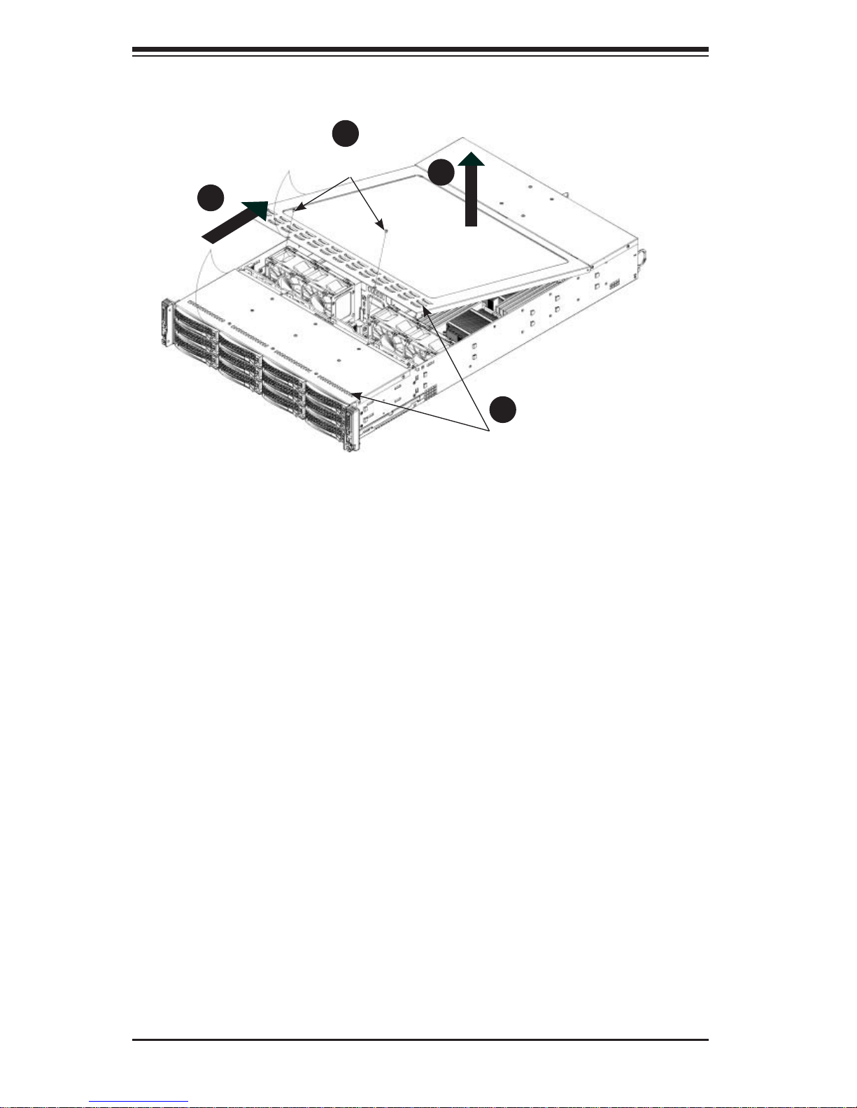
Removing the Chassis Cover and Protective Film
1. Remove the two screws which secure the top cover onto the chassis as
shown above.
2. Lift the top cover up and off the chassis.
3. Peel off the protective fi lm covering the top cover and the top of the chassis
4. Check that all ventilation openings on the top cover and the top of the chassis
are clear and unobstructed.
Checking the Components and Setup
1. You may have one or two processors already installed into the serverboard.
Each processor needs its own heat sink. See Chapter 5 for instructions on
processor and heat sink installation.
2. Your SUPERSERVER 6027TR-DTRF+/D70RF+/D71RF+ server system may
have come with system memory already installed. Make sure all DIMMs
are fully seated in their slots. For details on adding system memory, refer to
Chapter 5.
3. If desired, you can install add-on cards to the system. See Chapter 5 for
details on installing PCI add-on cards.
4. Make sure all power and data cables are properly connected and not blocking
the chassis airfl ow. Also make sure that no cables are positioned in front of
the fans. See Chapter 5 for details on cable connections.
2-8
SUPERSERVER 6027TR-DTRF+/D70RF+/D71RF+ User's Manual
Figure 2-5. Accessing the Inside of the System
Remove two
screws
Check Ventilation
Openings
1
2
1
3
1
4
1
1
2-7 Checking the Drive Bay Setup
Next, you should check to make sure the peripheral drives and the SATA drives
have been properly installed and all connections have been made.
Checking the Drives
1. All drives are accessable from the front of the server. A hard drive can be
installed and removed from the front of the chassis without removing the top
chassis cover.
2. Depending upon your system's confi guration, your system may have one or
more drives already installed. If you need to install hard drives, please refer to
Chapter 6.
Checking the Airfl ow
1. Airfl ow is provided by four hot-swappable 8-cm chassis cooling fans. The
system component layout was carefully designed to direct suffi cient cooling
airfl ow to the components that generate the most heat.
2. Note that all power and data cables have been routed in such a way that they
do not block the airfl ow generated by the fans.
Providing Power
1. Plug the power cord(s) from the power supply unit(s) into a high-quality
power strip that offers protection from electrical noise and power surges. It is
recommended that you use an uninterruptible power supply (UPS).
2. Depress the power on button on the front of the chassis.
Chapter 3: System Interface
3-1
Chapter 3
System Interface
3-1 Overview
There are several LEDs on the control panel and on the drive carriers to keep you
constantly informed of the overall status of the system. SC827 models include
two front panels on the handles of the chassis which control each of the systems.
This chapter explains the meanings of all LED indicators and the appropriate
response you may need to take.
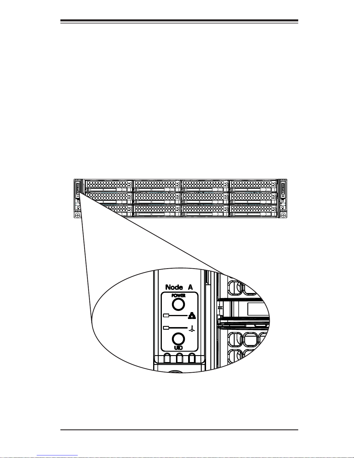
Figure 3-1: Control Panel
SUPERSERVER 6027TR-DTRF+/D70RF+/D71RF+ User's Manual
3-2
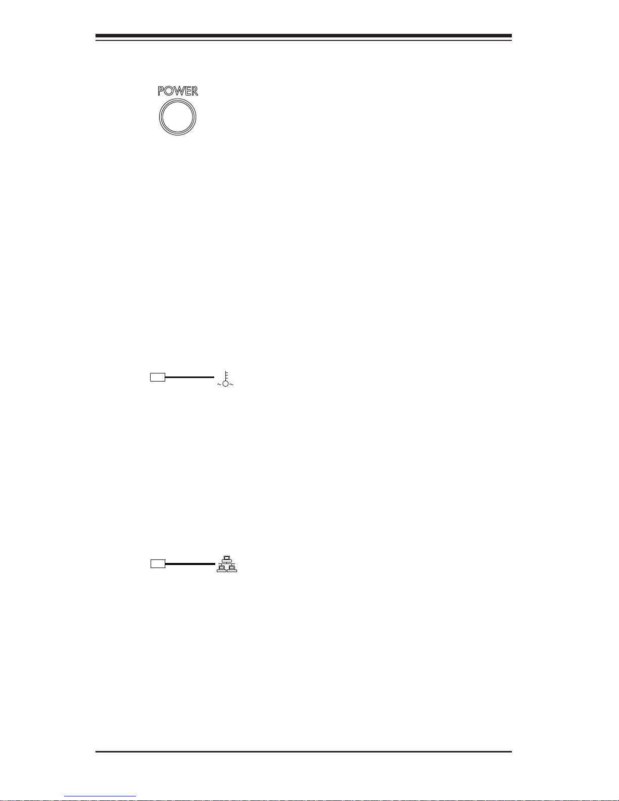
3-2 Control Panel Button
• Power: The main power button on each of the two control panels is used to
apply or remove power from the power supply to each of the two systems in
the chassis. Turning off system power with this button removes the main power,
but keeps standby power supplied to the system. Therefore, you must unplug
system before servicing.
3-3 Control Panel LEDs
The two control panels are located on the front handle of the SC827 chassis. Each
control panel has three LEDs. These LEDs provide you with critical information
related to different parts of the system. This section explains what each LED
indicates when illuminated and any corrective action you may need to take.
• Overheat: This LED is illuminated when an overheat condition occurs.
A solid red LED indicates an overheat condition in the system.
A fl ashing red LED which fl ashes in one second intervals indicates a fan failure.
A fl ashing red LED which fl ashes in four second interfals indicates a power
failure. Check the routing of the cables and make sure all fans are present and
operating normally. You should also check to make sure that the chassis covers
and air shrouds are installed. Finally, verify that the heatsinks are installed
properly. This LED will remain fl ashing or on as long as the temperature is too
high or a fan does not function properly.
• NIC1: Indicates network activity on GLAN1 when fl ashing.

Chapter 3: System Interface
3-3
3-4 Drive Carrier LEDs
The server chassis uses SATA drives.
SATA Drives
Each SATA drive carrier has two LEDs.
• Blue: Each Serial ATA drive carrier has a green LED. When illuminated, this
green LED (on the front of the SATA drive carrier) indicates drive activity. A
connection to the SATA backplane enables this LED to blink on and off when
that particular drive is being accessed.
• Red: The red LED to indicate an SATA drive failure. If one of the SATA drives
fail, you should be notifi ed by your system management software.

SUPERSERVER 6027TR-DTRF+/D70RF+/D71RF+ User's Manual
3-4
Notes
 Loading...