

Supermicro SUPER P6DKS, SUPER P6DKE, SUPER P6SKE, SUPER P6SKS, SUPER P6DKF User Manual

SUPER
SUPER P6DKF
SUPER P6DKS/P6DKE
SUPER P6SKS/P6SKE
®
USER’S MANUAL
Revision 1.1

The information in this User’s Manual has been carefully reviewed and is believed to be
accurate. The vendor assumes no responsibility for any inaccuracies that may be
contained in this document, makes no commitment to update or to keep current the
information in this manual, or to notify any person or organization of the updates.
SUPERMICRO COMPUTER reserves the right to make changes to the product described in
this manual at any time and without notice. This product, including software, if any, and
documentation may not, in whole or in part, be copied, photocopied, reproduced, translated
or reduced to any medium or machine without prior written consent.
IN NO EVENT WILL SUPERMICRO COMPUTER BE LIABLE FOR DIRECT, INDIRECT,
SPECIAL, INCIDENTAL, OR CONSEQUENTIAL DAMAGES ARISING FROM THE USE OR
INABILITY TO USE THIS PRODUCT OR DOCUMENTATION, EVEN IF ADVISED OF THE
POSSIBILITY OF SUCH DAMAGES. IN PARTICULAR, THE VENDOR SHALL NOT HAVE
LIABILITY FOR ANY HARDWARE, SOFTWARE, OR DATA STORED OR USED WITH THE
PRODUCT, INCLUDING THE COSTS OF THE REPAIRING, REPLACING, OR
RECOVERING SUCH HARDWARE, SOFTWARE, OR DATA.
Unless you request and receive written permission from SUPERMICRO COMPUTER, you
may not copy any part of this document.
Information in this document is subject to change without notice. Other products and
companies referred to herein are trademarks or registered trademarks of their respective
companies or mark holders.
Copyright © 1997 by SUPERMICRO COMPUTER INC.
All rights reserved.
Printed in the United States of America.

Preface
About This Manual
This manual is written for system houses, PC technicians and
knowledgeable PC end users. It provides information for the installation and use of SUPER P6DKF/P6DKS/P6DKE/P6SKS/P6SKE
motherboard. SUPER P6DKF/P6DKS/P6DKE supports Pentium II
300/266/233 MHz. SUPER P6SKS/P6SKE supports 200/180/166/
150 MHz Pentium Pro and 300/266/233 MHz Pentium II processors.
The Pentium II processor with the Dual Independent Bus Architecture is housed in a new package technology called the Single Edge
Contact (S.E.C.) cartridge. This new cartridge package and its associated "Slot 1" infrastructure will provide the headroom for future
high-performance processors.
Manual Organization
Chapter 1, Introduction, describes the features, specifications and
performance of the SUPER P6DKF/P6DKS/P6DKE/P6SKS/P6SKE
system board, provides detailed information about the chipset, and
offers warranty information.
Refer to Chapter 2, Installation, for instructions on how to install the
Pentium II processor, the retention mechanism, and the heat sink
support. This chapter provides you with the instructions for handling static-sensitive devices. Read this chapter when you want to
install or remove SIMM memory modules and to mount the system
board in the chassis. Also refer to this chapter to connect the floppy
and hard disk drives, IDE interfaces, parallel port, serial ports, as
well as the cables for the power supply, reset cable, Keylock/Power
LED, speaker and keyboard.
iii

SUPER P6DKF/P6DKS/P6DKE/P6SKS/P6SKE User’s Manual
If you encounter any problem, please see Chapter 3, Troubleshooting, which describes troubleshooting procedures for video, memory, and the setup configuration stored in memory. Instructions are
also included on contacting a technical assistance support representative and returning merchandise for service and the BBS# for
BIOS upgrades.
iv

Preface
Table of Contents
Preface
About This Manual ......................................................................................... iii
Manual Organization...................................................................................... iii
Chapter 1:
1-1 Overview............................................................................................... 1-1
SUPER P6DKF ............................................................................. 1-1
SUPER P6DKS ............................................................................. 1-2
SUPER P6DKE ............................................................................. 1-3
SUPER P6SKS/P6SKE ................................................................ 1-4
SUPER P6DKF Motherboard Layout ........................................ 1-5
SUPER P6DKS Motherboard Layout........................................ 1-6
SUPER P6DKE Motherboard Layout........................................ 1-7
SUPER P6SKS Motherboard Layout ........................................ 1-8
SUPER P6SKE Motherboard Layout ........................................ 1-9
SUPER P6DKF Features .......................................................... 1-10
SUPER P6DKS Features.......................................................... 1-11
SUPER P6DKE Features.......................................................... 1-12
SUPER P6SKS Features .......................................................... 1-13
SUPER P6SKE Features .......................................................... 1-14
1-2 Power Supply .................................................................................... 1-15
1-3 Chipset Overview.............................................................................. 1-15
1-4 National Semiconductor Super I/O................................................ 1-16
1-5 AIC 7880 SCSI Controller................................................................ 1-16
1-6 System Overheat Thermal Control ................................................1-17
1-7 Warranty, Technical Support, and Service .................................. 1-18
Parts.............................................................................................. 1-18
BIOS .............................................................................................. 1-18
Labor............................................................................................. 1-18
v

SUPER P6DKF/P6DKS/P6DKE/P6SKS/P6SKE User’s Manual
Returns......................................................................................... 1-18
Chapter 2: Installation
2-1 Pentium II Processor Installation ................................................... 2-1
OEM Pentium II and Heat Sink Support.................................. 2-5
Removing the Pentium II Processor........................................ 2-6
2-2 Static-Sensitive Devices ................................................................... 2-6
Precautions ................................................................................... 2-7
Unpacking...................................................................................... 2-7
2-3 Changing the CPU Speed ............................................................... 2-8
Turbo Function.............................................................................. 2-8
2-4 Mounting the Motherboard in the Chassis ................................... 2-9
2-5 Connecting Cables ............................................................................ 2-9
Power Supply Connectors.......................................................... 2-9
PW_ON Connector ...................................................................... 2-11
Infra-Red Connector ...................................................................2-11
Reset Cable Connector ............................................................ 2-12
Keylock/Power LED Cable Connector ................................... 2-12
Hard Drive LED .......................................................................... 2-13
Speaker Cable Connector........................................................ 2-13
SCSI LED ..................................................................................... 2-14
Back-up Cooling Fan and Buzzer Connectors ..................... 2-14
Thermal Control Connector ..................................................... 2-15
Buzzer Control............................................................................. 2-16
Overheat LED .............................................................................. 2-16
ATX PS/2 Keyboard and Mouse Ports ................................... 2-17
Universal Serial Bus .................................................................. 2-17
ATX Serial Ports ......................................................................... 2-18
Serial Ports.................................................................................. 2-18
CMOS Clear................................................................................. 2-19
External Battery ........................................................................... 2-19
vi

Table of Contents
2-6 Installing/Removing the SIMM Modules ...................................... 2-20
SIMM Module Installation .......................................................... 2-20
Removing SIMM Modules ......................................................... 2-21
2-7 Connecting Parallel, FDD and HDD ............................................ 2-22
Parallel Port Connector ............................................................ 2-23
Floppy Connector ....................................................................... 2-24
IDE Interfaces ............................................................................. 2-25
SCSI Connectors......................................................................... 2-26
Chapter 3: Troubleshooting
3-1 Troubleshooting Procedures ........................................................... 3-1
No Video ........................................................................................ 3-1
Troubleshooting Flowchart ........................................................ 3-2
Memory Error ................................................................................. 3-3
Losing the System’s Setup Configuration.............................. 3-3
3-2 Technical Support Procedures........................................................ 3-4
3-3 Returning Merchandise for Service................................................ 3-4
vii

SUPER P6DKF/P6DKS/P6DKE/P6SKS/P6SKE User’s Manual
viii

Chapter 1: Introduction
Chapter 1
Introduction
1-1 Overview
SUPER P6DKF
SUPER P6DKF is a full AT size computer system board that offers a
highly optimized and more robust performance for servers and
high-end workstations. Based on the Intel 440FX chipset, it supports dual Pentium® II 233/266/300 MHz or higher processors, up to
1 GB FPM and EDO memory, 5 PCI, and 4 ISA slots.
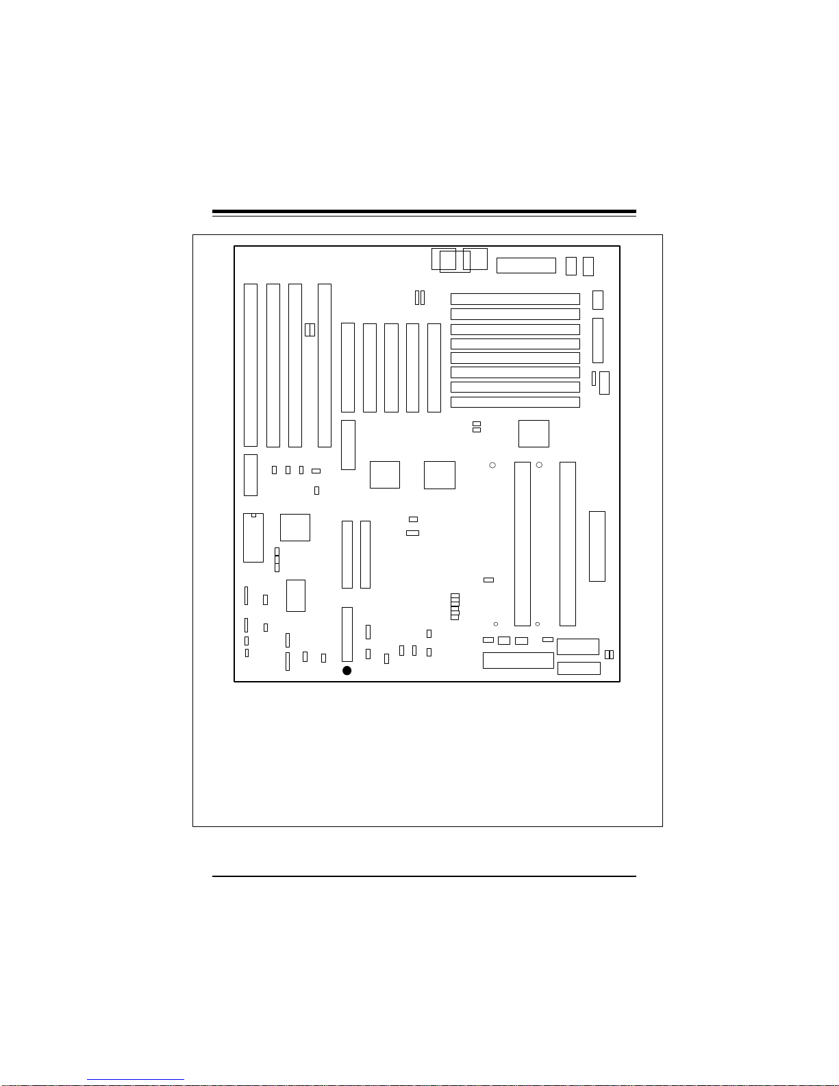
Figure 1-1. SUPER P6DKF Motherboard Picture
1-1

SUPER P6DKF/P6DKS/P6DKE/P6SKS/P6SKE User’s Manual
SUPER P6DKS
SUPER P6DKS is an ATX size motherboard that supports dual
Pentium II 233/266/300 MHz or higher processors. It has an onboard Adaptec 2940 Ultra Wide SCSI controller with fast data transfer rate of up to 40 MB/s. This solution lowers the total cost of
ownership while providing an extra PCI slot to accommodate future
growth.
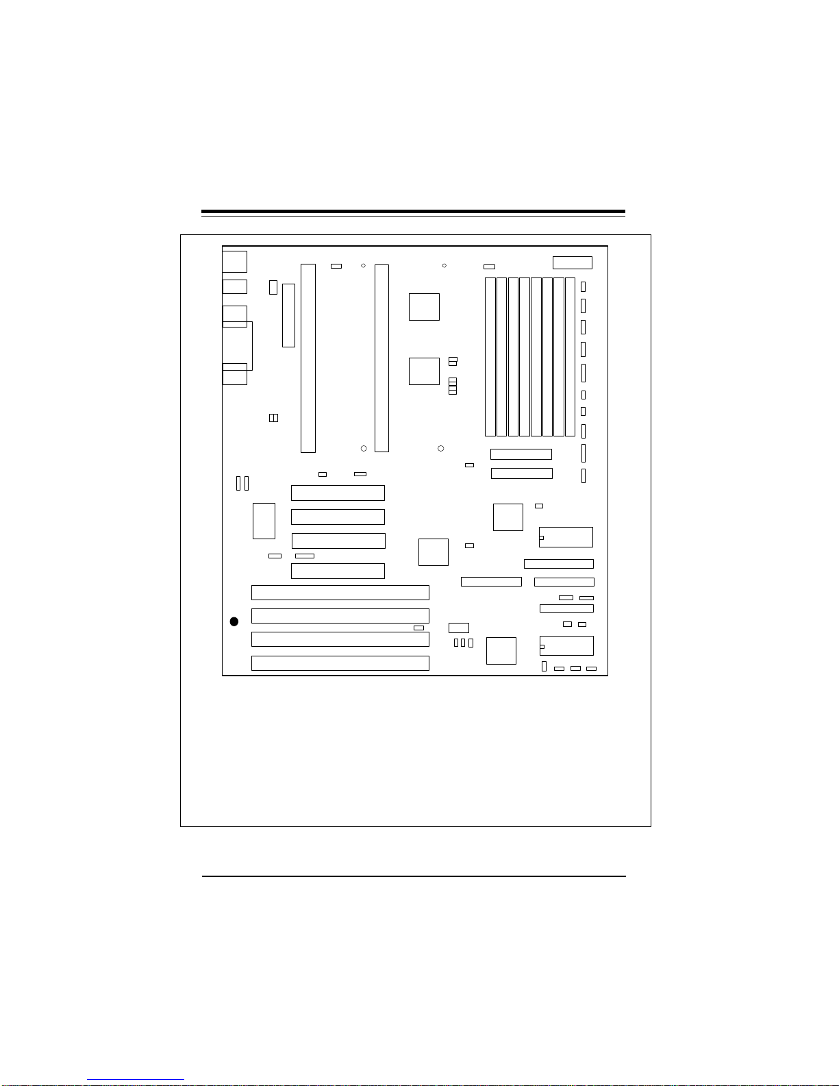
Figure 1-2. SUPER P6DKS Motherboard Picture
1-2

Chapter 1: Introduction
SUPER P6DKE
SUPER P6DKE is similar to SUPER P6DKS without the on-board
Adaptec SCSI controller. It is an ATX size motherboard that supports dual Pentium II 233/266/300 MHz or higher processors and
can accommodate a total of 1 GB FPM or EDO memory. It comes
with four PCI bus mastering slots and four ISA slots.
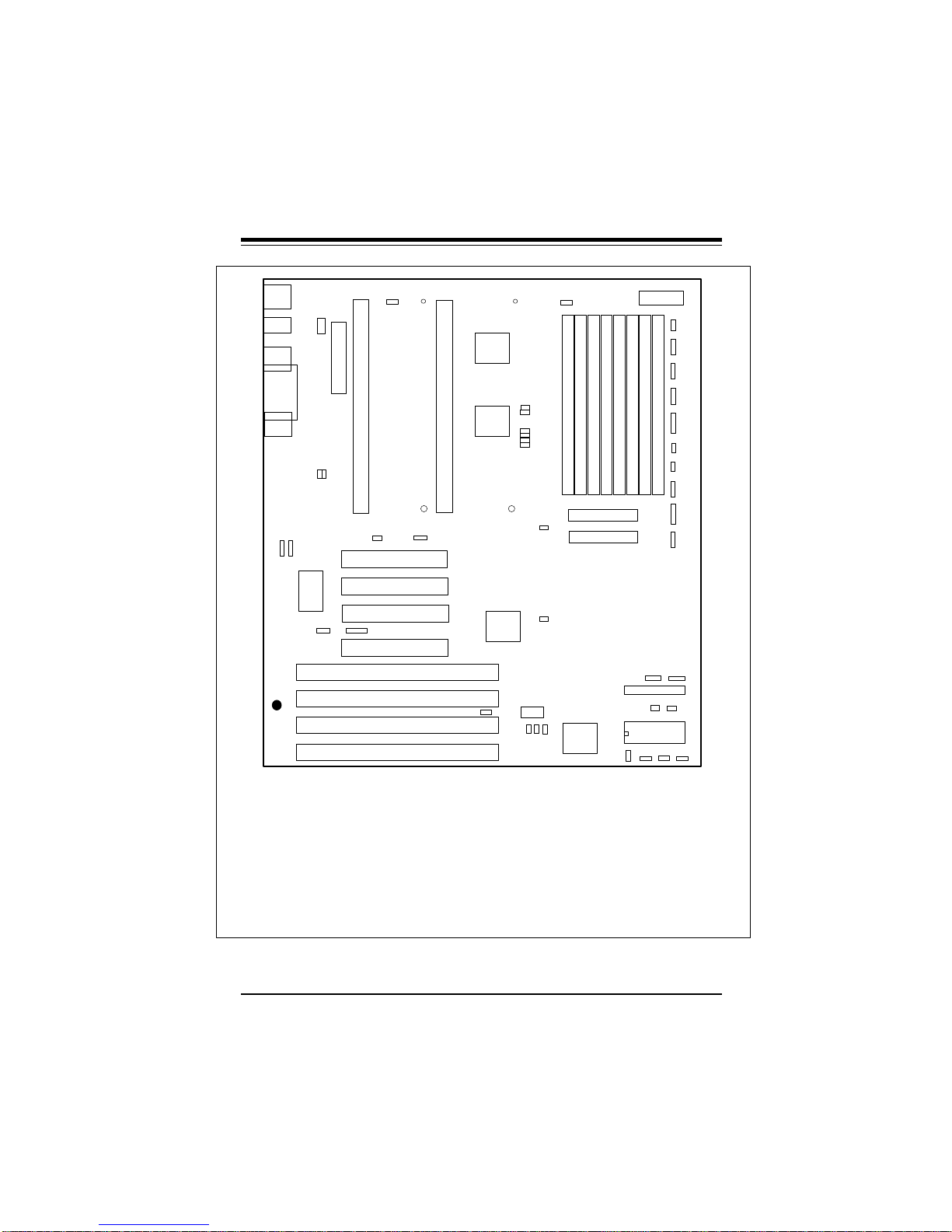
Figure 1-3. SUPER P6DKE Motherboard Picture
1-3

SUPER P6DKF/P6DKS/P6DKE/P6SKS/P6SKE User’s Manual
SUPER P6SKS/P6SKE
SUPER P6SKS/P6SKE is a function-enhanced ATX 2.01-compliant
motherboard. Its unique design supports both Pentium Pro and
Pentium II processors. SUPER P6SKS/P6SKE incorporates the
Intel 440FX chipset. A "Slot 1" socket is available for a Pentium II
processor and a Socket 8 for a Pentium Pro processor. It supports
up to 768 MB memory, 4 PCI and 4 ISA slots. SUPER P6SKS has
an on-board SCSI controller which is 100% compatible with an
Adaptec 2940 UW. SUPER P6SKE does not have an on-board
SCSI.
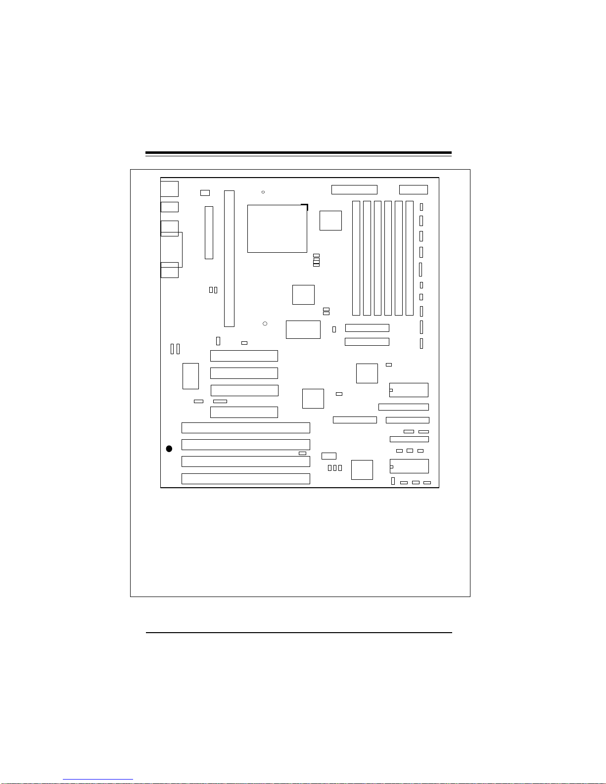
Figure 1-4. SUPER P6SKS Motherboard Picture
1-4
Chapter 1: Introduction
J28 J29
J834
U834
BIOS
JP20
KEYLOCK
1
JP880
1
J22
SPEAKER
JP38
1
1
JP39
1
SMI SW
JP21
1
RESET
J31 J32
1 1 1
U831
J827
1
J828
1
J829
1
BT1
BATTERY
JP97
1
1
JP96
IR CON
SUPER
J832 J831 J833
-
+
JP89
ALARM
1
JP27
JP26
JP13
1
FAN1
1
1
JP35
J20 J824
5V POWER
Bank3
Bank3
Bank2
Bank2
Bank1
Bank1
Bank0
Bank0
K1
JP34
1
J1
VRM 1
J83
PS/2
MOUSE
J35 J36
1
1
USB1
USB2
1
J39
JP884
JP15
1
JP93 JP92
1
JP94
1
JP90
1
J40
JP36
JP37
JP32
JP31
JP30
JP29
J38
J86
J88
1
1
JP42
J830
1
JP88
1
J37 J27
J27C
J12
J11
1
1
IDE 1
IDE 2
J85
1
J23
HD LED
1
FLOPPY
JP95
JP91
1
1
® 3V SUPPLY
P6DKF
J81 AT KB
U5 U13
J82
PS/2 KB
1
1
1
1
U6
Slot 1
J818
1
1
COM1
COM2
J84 PS/2 MOUSE
1
J817
1
PARALLEL
J208
1 1
JP881 Ext Battery
Power
+5V Extra
K2
J2
VRM
2
Slot 2
FAN2
VR3
1
1
J21
JP22
JP23
VR4
——–—— Manufacturer Settings ————
J86: 1-2 JP15: 2-3
J88: 1-2 JP26: OFF
J827: ON JP27: ON
J828: ON JP38: OFF
J829: ON JP88: OFF
JP13: 2-3 JP95: 2-3
JP880: 1-2 (default) JP884: OFF
2-3 CMOS Clear
JP42: ON (ISA CLK=PCI CLK/4)
OFF (ISA CLK=PCI CLK/3)
——–———————–———–——–——–—
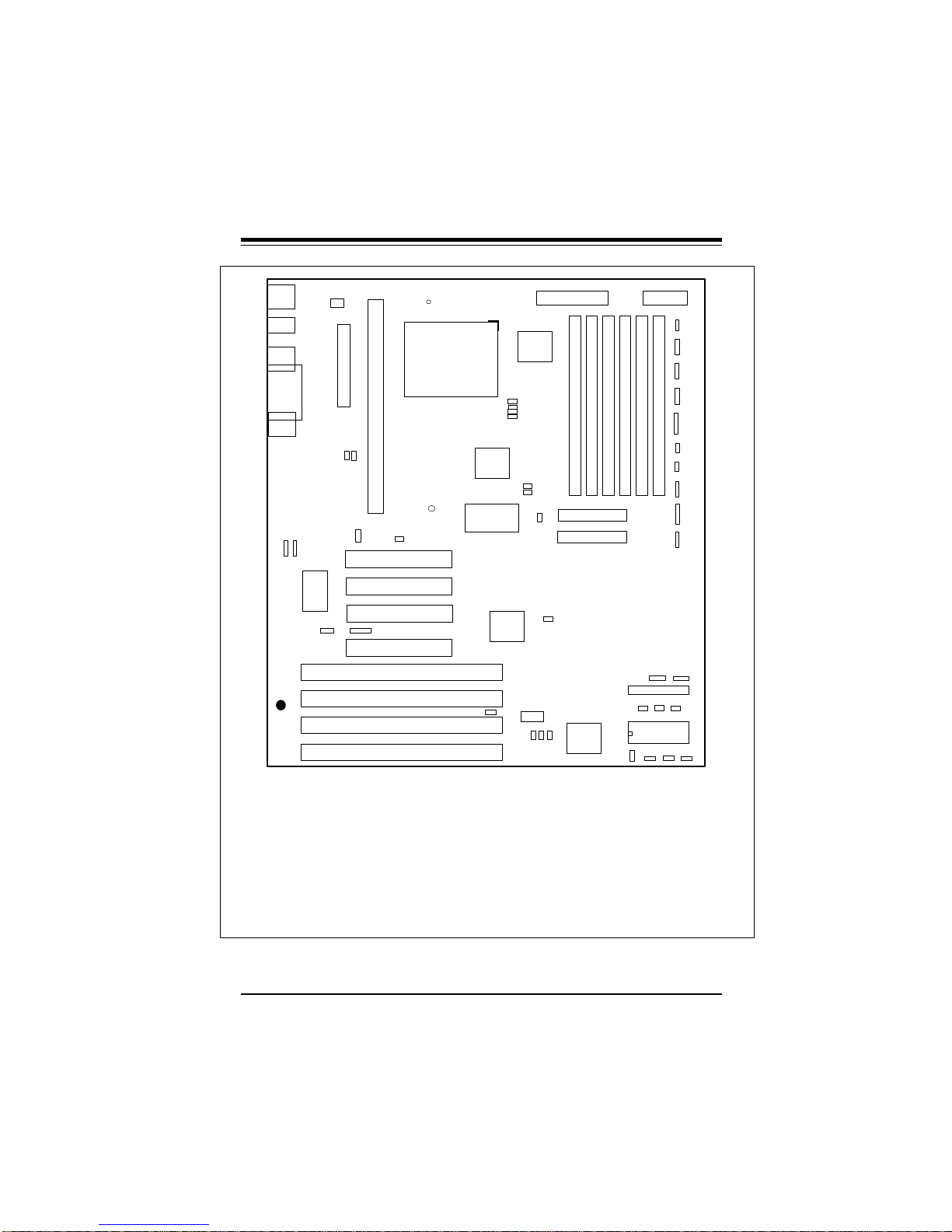
Figure 1-5. SUPER P6DKF Motherboard Layout
———–——————Pentium II CPU Speed—–——————
233 266 300 333 366 400
JP29 OFF ON OFF ON OFF ON
JP30 OFF ON ON OFF OFF ON
JP31 ON OFF OFF OFF OFF ON
JP32 ON ON ON ON ON OFF
JP36 OFF OFF OFF OFF OFF OFF
JP37 ON ON ON ON ON ON
——–—–————————————————————————
1-5
SUPER P6DKF/P6DKS/P6DKE/P6SKS/P6SKE User’s Manual
1 1
®
PS/2 MOUSE
J34
USB
J35
J36
BATTERY
J32
J31
J29
J28
J82
PS/2 KB
JP35
1
J824
COM2
J817
PRINTER
J818
COM1
-
BT1
+
JP880
1
JP37
JP36
J21
CPU 1
ATX POWER
JP884 JP13
1
FAN1
JP881
Ext Battery
1
S UPER P6DKS
——–—— Manufacturer Settings ————
J86: 1-2 JP13: 2-3
J88: 1-2 JP15: 2-3
J827: ON JP26: OFF
J828: ON JP27: ON
J829: ON JP38: OFF
JA4: OFF JP88: ON
JP884: OFF JP95: 2-3
JP880: 1-2 (default)
2-3 CMOS Clear
To clear the CMOS completely,
disconnect the power source.
JP42: ON (ISA CLK=PCI CLK/4)
OFF (ISA CLK=PCI CLK/3)
——–———————–———–——–——–—
CPU 2
U5
U6
JP27
JP26
JP29
JP30
JP31
JP32
JP38
1
J40
J39
J38
J37
U13
JP42
1
1
———Pentium II CPU Speed—–————
JP29 OFF ON OFF
JP30 OFF ON ON
JP31 ON OFF OFF
JP32 ON ON ON
JP36 OFF OFF OFF
JP37 ON ON ON
———————————————————
J980
J88
1
J827
233 266 300
EXT UW SCSI
J828
J829
FAN2
1
1
JA5
Bank3
U831
J21A
Bank2
Bank2
1
1
J85
J86
AT 3V POWER
Bank0
Bank1
Bank1
JA4
UA5
JA2
ULTRA SCSI
JA1
UW SCSI
ALARM JP89 JP95
FLOPPY
1 1
U834
BIOS
JP92
1
1 1 1
1
1
1
1
Bank0
1
1
1
1
1
11
JP88 JP90
JP882
PW_ON
1
JP97
JP91 JP93
JP15
JA3
SCSI
LED
J23
IDE
LED
JP96
IR
CON
JP21
RESET
JP39
SMI SW
J22
SPEAK-
ER
JP20
KEY-
LOCK
1
1
1
1
Bank3
J11
IDE 1
J12
IDE 2
UA7
Figure 1-6. SUPER P6DKS Motherboard Layout
1-6
Chapter 1: Introduction
1 1
®
PS/2 MOUSE
J34
USB
J35
J36
BATTERY
J32
J31
J29
J28
J82
PS/2 KB
JP35
1
J824
COM2
J817
PRINTER
J818
COM1
-
BT1
+
1
JP880
JP37
JP36
J21
CPU 1
ATX POWER
JP884 JP13
1
FAN1
JP881
Ext Battery
1
SUPER P6DKE
——–—— Manufacturer Settings ————
J86: 1-2 JP13: 2-3
J88: 1-2 JP15: 2-3
J827: ON JP26: OFF
J828: ON JP27: ON
J829: ON JP38: OFF
JP884: OFF JP88: ON
JP880: 1-2 (default) JP95: 2-3
2-3 CMOS Clear
To clear the CMOS completely,
disconnect the power source.
JP42: ON (ISA CLK=PCI CLK/4)
OFF (ISA CLK=PCI CLK/3)
——–———————–———–——–——–—
CPU 2
U5
U6
JP27
JP26
JP29
JP30
JP31
JP32
JP38
1
J40
J39
J38
J37
U13
JP42
1
J980
1
J88
1
J827
———Pentium II CPU Speed—–————
233 266 300
JP29 OFF ON OFF
JP30 OFF ON ON
JP31 ON OFF OFF
JP32 ON ON ON
JP36 OFF OFF OFF
JP37 ON ON ON
———————————————————
J828
J829
FAN2
J21A
Bank2
Bank2
J85
J86
AT 3V POWER
Bank0
Bank0
Bank1
Bank1
ALARM JP89 JP95
11
FLOPPY
JP88 JP90
1 1
U834
BIOS
JP92
1
1 1 1
1
JP882
PW_ON
1
1
1
1
1
1
1
1
JP97
1
JP91 JP93
JP15
JA3
SCSI
LED
J23
IDE
LED
JP96
IR
CON
JP21
RESET
JP39
SMI SW
J22
SPEAK-
ER
JP20
KEY-
LOCK
1
1
Bank3
Bank3
J11
IDE 1
1
J12
IDE 2
1
U831
Figure 1-7. SUPER P6DKE Motherboard Layout
1-7
SUPER P6DKF/P6DKS/P6DKE/P6SKS/P6SKE User’s Manual
J82
PS/2 KB
JP35
PS/2
MOUSE
J34
USB
J824
COM2
J817
PRINTER
J818
COM1
J35
J36
1 1
BATTERY
-
BT1
+
JP880
1
J32
J31
®
J29
J28
K1
1
J1
JP37
JP36
FAN1
1
JP884
JP881
1
Ext Battery
S UPER P6SKS
——–—— Manufacturer Settings ————
J86: 1-2 JP15: 2-3
J88: 1-2 JP26: OFF
J827: ON JP27: ON
J828: ON JP38: OFF
J829: ON JP88: ON
JA4: OFF JP95: 2-3
JP884: OFF (Pentium II)
ON (Pentium Pro)
JP880: 1-2 (default)
2-3 CMOS Clear
To clear the CMOS completely,
disconnect the power source.
JP42: ON (ISA CLK=PCI CLK/4)
OFF (ISA CLK=PCI CLK/3)
——–———————–———–——–——–—
U33
CPU
J40
J39
J38
J37
J21
ATX POWER
1
U5
JP29
JP30
JP31
JP32
U6
VR3
U13
J980
J88
1
1
—–—–—Pentium Pro CPU Speed—–——
JP29 OFF OFF ON ON
JP30 ON ON OFF OFF
JP31 ON ON ON ON
JP32 ON ON ON ON
JP36 ON OFF ON OFF
JP37 OFF ON OFF ON
——–—–——————————–—————
———Pentium II CPU Speed—–————
JP29 OFF ON OFF
JP30 OFF ON ON
JP31 ON OFF OFF
JP32 ON ON ON
JP36 OFF OFF OFF
JP37 ON ON ON
———————————————————
Bank2
Bank2
JP27
JP26
JP38
J827
JP42
1
J828
1
1
JA5
EXT UW SCSI
U831
J829
J11
IDE 1
J12
IDE 2
UA7
J86
150 166 180 200
233 266 300
Bank1
Bank1
JA4
1
ULTRA SCSI
1
ALARM JP89 JP95
J85
JP94
1
JP92
1
J21A
AT 3V POWER
Bank0
Bank0
UA5
JA2
JA1
UW SCSI
FLOPPY
JP88
JP90
1 1
U834
BIOS
1 1 1
1
1
1
1
1
1
1
1
1
1
11
JP15
JP882
PW_ON
JA3
SCSI
LED
J23
IDE
LED
JP96
IR CON
JP21
RESET
JP39
SMI SW
J22
SPEAK-
ER
JP20
KEY-
LOCK
JP97
JP91 JP93
1
1
1
Figure 1-8. SUPER P6SKS Motherboard Layout
1-8
Chapter 1: Introduction
J82
PS/2 KB
JP35
PS/2
MOUSE
J34
USB
J824
COM2
J817
PRINTER
J818
COM1
J35
J36
1 1
BATTERY
-
BT1
+
JP880
1
J32
J31
®
J29
J28
K1
1
J1
JP37
JP36
FAN1
1
JP884
JP881
1
Ext Battery
S UPER P6SKE
——–—— Manufacturer Settings ————
J86: 1-2 JP15: 2-3
J88: 1-2 JP26: OFF
J827: ON JP27: ON
J828: ON JP38: OFF
J829: ON JP88: ON
JP95: 2-3
JP884: OFF (Pentium II)
ON (Pentium Pro)
JP880: 1-2 (default)
2-3 CMOS Clear
To clear the CMOS completely,
disconnect the power source.
JP42: ON (ISA CLK=PCI CLK/4)
OFF (ISA CLK=PCI CLK/3)
——–———————–———–——–——–—
Figure 1-9. SUPER P6SKE Motherboard Layout
U33
CPU
J40
J39
J38
J37
J21
ATX POWER
1
U5
JP29
JP30
JP31
JP32
U6
VR3
U13
J980
J88
1
1
—–—–—Pentium Pro CPU Speed—–——
JP29 OFF OFF ON ON
JP30 ON ON OFF OFF
JP31 ON ON ON ON
JP32 ON ON ON ON
JP36 ON OFF ON OFF
JP37 OFF ON OFF ON
——–—–——————————–—————
———Pentium II CPU Speed—–————
JP29 OFF ON OFF
JP30 OFF ON ON
JP31 ON OFF OFF
JP32 ON ON ON
JP36 OFF OFF OFF
JP37 ON ON ON
———————————————————
Bank2
Bank2
JP27
JP26
JP38
J827
JP42
1
J828
1
1
J829
U831
J11
IDE 1
J12
IDE 2
J86
150 166 180 200
233 266 300
Bank1
Bank1
ALARM JP89 JP95
J85
JP94
1
JP92
1
1 1 1
J21A
AT 3V POWER
1
1
1
1
Bank0
Bank0
1
1
1
1
1
1
11
FLOPPY
JP88
JP90
1 1
U834
BIOS
JP15
JP882
PW_ON
JA3
SCSI
LED
J23
IDE
LED
JP96
IR CON
JP21
RESET
JP39
SMI SW
J22
SPEAK-
JP20
KEY-
LOCK
JP97
JP91 JP93
ER
1
1-9

SUPER P6DKF/P6DKS/P6DKE/P6SKS/P6SKE User’s Manual
SUPER P6DKF Features
The following list covers the general features of SUPER P6DKF:
CPU
• Dual Pentium II processor 233/266/300 MHz
Memory
• 1 GB Fast Page DRAM, ECC or EDO
• Error Checking and Correction and Parity Checking support
Chipset
• Intel 440FX
Expansion Slots
• 5 PCI slots
• 4 ISA slots
BIOS
• AMI® Flash BIOS
• DMI 2.0, Plug and Play (PnP), and boot block support
On-Board I/O
• 2 EIDE interfaces support Mode 4
• 1 floppy interface
• 2 Fast UART 16550 serial ports
• EPP (Enhanced Parallel Port) and ECP (Extended Capabilities
Port) parallel port
• PS/2 mouse and PS/2 keyboard
• Infra-red port
• 2 USB ports
• System Management Port
System Overheat Temperature Control
• Built-in alarm
• Back-up fan controller
Dimensions
• Full AT
Made in USA
1-10
 Loading...