

Supermicro SUPER P6DGE, SUPER P6DGU, SUPER P6SGU, SUPER P6DGS User Manual

®
SUPER P6DGS
SUPER P6DGE
SUPER P6DGU
SUPER P6SGU
USER’S
MANUAL
Revision 2.2
SUPER

The information in this User’s Manual has been carefully reviewed and is believed to be
accurate. The vendor assumes no responsibility for any inaccuracies that may be contained
in this document, makes no commitment to update or to keep current the information in this
manual, or to notify any person or organization of the updates.
Please Note: For the
most up-to-date version of this manual, please see our web site at
www.supermicro.com.
SUPERMICRO COMPUTER reserves the right to make changes to the product described in
this manual at any time and without notice. This product, including software, if any, and
documentation may not, in whole or in part, be copied, photocopied, reproduced, translated or
reduced to any medium or machine without prior written consent.
IN NO EVENT WILL SUPERMICRO COMPUTER BE LIABLE FOR DIRECT, INDIRECT,
SPECIAL, INCIDENTAL, OR CONSEQUENTIAL DAMAGES ARISING FROM THE USE OR
INABILITY TO USE THIS PRODUCT OR DOCUMENTATION, EVEN IF ADVISED OF THE
POSSIBILITY OF SUCH DAMAGES. IN PARTICULAR, THE VENDOR SHALL NOT HAVE
LIABILITY FOR ANY HARDWARE, SOFTWARE, OR DATA STORED OR USED WITH THE
PRODUCT, INCLUDING THE COSTS OF THE REPAIRING, REPLACING, INTEGRATING OR
RECOVERING SUCH HARDWARE, SOFTWARE OR DATA.
Unless you request and receive written permission from SUPERMICRO COMPUTER, you may
not copy any part of this document.
Information in this document is subject to change without notice. Other products and
companies referred to herein are trademarks or registered trademarks of their respective
companies or mark holders.
Copyright © 2000 by SUPERMICRO COMPUTER INC.
All rights reserved.
Printed in the United States of America.

Preface
About This Manual
This manual is written for system houses, PC technicians and
knowledgeable PC end users. It provides information for the installation and
use of the SUPER P6DGS/P6DGE/P6DGU/P6SGU motherboard. The SUPER P6DGS/P6DGE/P6DGU/P6SGU supports Pentium II 233-333 MHz processors at a 66MHz bus speed and Pentium II/III 350-700 MHz processors at
a 100MHz bus speed and Slot 1 Celeron processors of up to 466 MHz. The
SUPER P6DGU/P6DGS/P6DGE supports single or dual Pentium II/III processors and the SUPER P6SGU supports a single Pentium II/III processor.
Please refer to the support section of our web site (http://
www.supermicro.com/TechSupport.htm) for a complete listing of supported
processors.
The Pentium II/III processor with the Dual Independent Bus Architecture is
housed in a package technology called a Single Edge Contact Cartridge
(S.E.C.C.). This new cartridge package and its associated "Slot 1" infrastructure will provide the headroom for future high-performance processors.
Manual Organization
Chapter 1, Introduction, describes the features, specifications and performance of the SUPER P6DGS/P6DGE/P6DGU/P6SGU system board and provides detailed information about the chipset.
Refer to Chapter 2, Installation, for instructions on how to install the Pentium
II/III processor, the retention mechanism and the heat sink support. This
chapter provides you with the instructions for handling static-sensitive devices. Read this chapter when you want to install DIMM modules and to
mount the system board in the chassis. Also refer to this chapter to connect
the floppy and hard disk drives, IDE interfaces, parallel and serial ports as
well as the cables for the power supply, reset cable, keylock/power LED,
speaker and keyboard.
If you encounter any problems, please see Chapter 3, Troubleshooting, which
describes troubleshooting procedures for video, memory and the setup configuration stored in memory. For quick reference, a general FAQ [frequently
iii
Preface

SUPER P6DGS/P6DGE/P6DGU/P6SGU User’s Manual
asked questions] section is provided. Instructions are also included for technical support procedure, for returning merchandise for service and for BIOS
upgrades.
See Chapter 4 for configuration data and BIOS features.
Chapter 5 has information on running setup and includes the default settings
for Standard Setup, Advanced Setup, Chipset function, Power Management,
PCI/PnP Setup and Peripheral Setup.
Appendix A offers information on BIOS error beep codes and messages.
Appendix B shows post diagnostic error messages.
iv

Preface
Table of Contents
Preface
About This Manual ...................................................................................................... ii i
Manual Organization ................................................................................................... i ii
Jumper/Connector Quick Reference ........................................................................ viii
Front Control Panel Connector .................................................................................. ix
Chapter 1: Introduction
1-1 Overview .......................................................................................................... 1 -1
SUPER P6DGS ........................................................................................ 1-2
SUPER P6DGS Motherboard Layout .................................................... 1- 3
SUPER P6DGE ........................................................................................ 1-4
SUPER P6DGE Motherboard Layout .................................................... 1- 5
SUPER P6DGU ......................................................................................... 1- 6
SUPER P6DGU Motherboard Layout ..................................................... 1- 7
SUPER P6SGU ......................................................................................... 1- 8
SUPER P6SGU Motherboard Layout ..................................................... 1 -9
440GX AGP Chipset: System Block Diagram .................................... 1-10
Motherboard Features ........................................................................... 1-11
1-2 Chipset Overview .......................................................................................... 1-13
1-3 PC Health Monitoring................................................................................... 1-13
1-4 Solo-1 PCI
Audio
Drive................................................................................. 1-15
1-5 ACPI/PC 98 Features .................................................................................. 1-16
1-6 Power Supply ................................................................................................ 1-17
1-7 Super I/O ........................................................................................................ 1-18
1-8 AIC-7895 SCSI Controller ............................................................................ 1-19
1-9 AIC-7890 SCSI Controller ............................................................................ 1-19
Chapter 2: Installation
2-1 Static-Sensitive Devices ................................................................................ 2- 1
Precautions ............................................................................................... 2- 1
Unpacking ................................................................................................. 2 -1
2-2 Pentium II/III Processor Installation ............................................................ 2 -1
Installation of the Universal Retention Mechanism ............................ 2- 4
2-3 Explanation and Diagram of Jumper/Connector ........................................ 2 -6
2-4 Changing the CPU Speed ............................................................................. 2 -6
2-5 Mounting the Motherboard in the Chassis .................................................. 2-7
2-6 Connecting Cables ......................................................................................... 2 -7
v

SUPER P6DGS/P6DGE/P6DGU/P6SGU User’s Manual
Power Supply Connector ........................................................................ 2-7
Secondary Power Connector .................................................................. 2 -7
Infrared Connector .................................................................................... 2- 7
PW_ON Connector .................................................................................... 2 -8
Reset Connector ...................................................................................... 2-8
Hard Drive LED ........................................................................................ 2 -8
Keylock/Power LED Connector .............................................................. 2-8
Speaker Connector .................................................................................. 2 -9
Power Save State Select ........................................................................ 2-9
ATX PS/2 Keyboard and Mouse Ports ................................................. 2-9
Universal Serial Bus ................................................................................ 2-9
ATX Serial Ports .................................................................................... 2-10
CMOS Clear ............................................................................................ 2-10
External Battery...................................................................................... 2-10
Wake-on-LAN.......................................................................................... 2-10
Fan Connectors...................................................................................... 2-10
Chassis Intrusion ................................................................................... 2-11
2-7 Installing DIMMs ........................................................................................... 2-11
DIMM Installation ................................................................................... 2-11
2-8 Connecting Parallel, Floppy and Hard Disk Drives ................................. 2-12
Parallel Port Connector ......................................................................... 2-13
Floppy Connector ................................................................................... 2-13
IDE Interfaces ......................................................................................... 2-13
SCSI Connectors .................................................................................... 2-14
68-Pin LVD SCSI Connector ................................................................. 2-15
AGP Port ................................................................................................. 2-16
Chapter 3: Troubleshooting
3-1 Troubleshooting Procedures ......................................................................... 3 -1
Before Power On ...................................................................................... 3 -1
Troubleshooting Flowchart ...................................................................... 3- 1
No Power ................................................................................................... 3-2
No Video .................................................................................................... 3-2
Memory Errors .......................................................................................... 3-2
Losing the System’s Setup Configuration ............................................ 3- 3
3-2 Technical Support Procedures ..................................................................... 3-3
3-3 Frequently Asked Questions ......................................................................... 3 -4
3-4 Returning Merchandise for Service ............................................................. 3- 7
vi

Table of Contents
Chapter 4: AMIBIOS
4-1 Introduction....................................................................................................... 4 - 1
4-2 BIOS Features ................................................................................................. 4- 2
BIOS Configuration Summary Screen ................................................... 4 -3
AMIBIOS Setup ......................................................................................... 4- 3
Chapter 5: Running Setup
5-1 Setup ................................................................................................................. 5 - 1
5-1-1 Standard Setup ............................................................................... 5 -1
5-1-2 Advanced Setup .............................................................................. 5 -3
5-1-3 Chipset Setup .................................................................................. 5 -7
5-1-4 Power Management ...................................................................... 5-13
5-1-5 PCI/PnP Setup .............................................................................. 5-15
5-1-6 Peripheral Setup ........................................................................... 5-18
5-2 Security Setup ................................................................................................ 5-20
5-2-1 Supervisor/User ............................................................................ 5-20
5-3 Utility Setup .................................................................................................... 5-21
5-3-1 Anti-Virus ....................................................................................... 5-21
5-3-2 Language ....................................................................................... 5-21
5-4 Default Settings ............................................................................................. 5-21
5-4-1 Optimal Default ............................................................................. 5-21
5-4-2 Fail-Safe Default........................................................................... 5-22
Appendices:
Appendix A: BIOS Error Beep Codes and Messages .........................................A -1
Appendix B: AMIBIOS Post Diagnostic Error Messages .................................... B -1
vii

SUPER P6DGS/P6DGE/P6DGU/P6SGU User’s Manual
viii
P6DGS/P6DGE P6DGU/P6SGU
Jumper
JB1, JB2, JB3, JB4
JBT1
JP20
JL2
JA5
JA6
JP11
Connector
J17
J18
J19
J20
J21
J32
J34
J36
JA1, JA2
JA3
JBT2
JF1
JF2
JL1
JOH1
JT1
JT2
JT3
SLED
WOL
Function Page
CPU/Bus Ratio Selection 2-6
CMOS Clear 2-10
Power Save State Select 2- 9
Manufacturer Default 1-3
JA1, JA3, SCSI Termination
(default on as terminated) 1-3
JA2 SCSI Termination
(default on as terminated) 1-9
Bus Speed 1-3,5
Function Page
USB 2-9
USB 2-9
Parallel Port 2-13
COM 1 2-10
COM 2 2-10
ATX Power Connector 2-7
PS/2 KB and Mouse 2-9
Secondary Power Connector 2-7
UW SCSI 2-14
SCSI 2-14
External Battery 2-10
IDE LED 2-8, 2-9
Keylock
Speaker
IR Connector 2-7, 2-8
PW_ON
Reset
Chassis Intrusion 2-11
Overheat LED Header 1-3,5
CPU 1 Fan 2-10
CPU 2 Fan 2-10
Thermal Control Fan 2-10
SCSI LED 1-3
Wake-on-LAN 2-10
Jumper
JB1, JB2, JB3, JB4
JBT1
JP20
S-TERM
BZ_ON
JP11
Connector
J17
J18
J19
J20
J21
J32
J34
J36
JA1
JA2
JA3
JBT2
JF1
JF2
JL1
JOH
JT1
JT2
JT3
SLED
WOL
Function Page
CPU/Bus Ratio Selection 2-6
CMOS Clear 2-10
Power Save State Select 2- 9
SCSI Termination
(default on as terminated) 1-7,9
Overheat Alarm Enable 1-11
Bus Speed 1-7,9
Function Page
USB 2-9
USB 2-9
Parallel Port 2-13
COM 1 2-10
COM 2 2-10
ATX Power Connector 2-7
PS/2 KB and Mouse 2-9
Secondary Power Connector 2-7
Ultra2 LVD/SE 2-15
UW SCSI 2-14
Ultra SCSI 2-14
External Battery 2-10
IDE LED 2-8, 2-9
Keylock
Speaker
IR Connector 2-7, 2-8
PW_ON
Reset
Chassis Intrusion 2-11
Overheat LED Header 1-7,9
CPU 1 Fan 2-10
CPU 2 Fan 2-10
Thermal Control Fan 2-10
SCSI LED
Wake-on-LAN 2-10
Jumper/Connector Quick Reference
ix
Preface
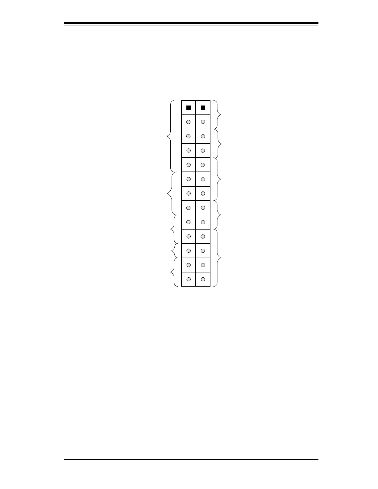
Front Control Panel Connector
Please see pages 2-7 through
2-9 for pin definitions.
Hard
Drive
LED
Keyboard
lock
Speaker
IR Con
Power On
X
Reset
JF2 JF1
X
Power
LED
11
X

Notes
Preface

Chapter 1: Introduction
1-1
Chapter 1
Introduction
1-1 Overview
The SUPER P6DGS/P6DGE/P6DGU/P6SGU supports Pentium II 233-333 MHz
processors at a 66MHz bus speed and Pentium II/III 350-700 MHz processors at a 100MHz bus speed. The SUPER P6DGU/P6DGS/P6DGE supports
single or dual Pentium II/III processors and the SUPER P6SGU supports a
single Pentium II/III processor. All four motherboards are based on Intel’s
440GX chipset, which enables 66/100 MHz system bus speed, Accelerated
Graphics Port (AGP), Wake-on-LANÔ , SDRAM, concurrent PCI and Ultra
DMA/33 for a 33 MB/s burst transfer rate.
While all of the motherboards are the ATX form factor, the P6DGU and
P6DGE have 5 PCI and 2 ISA slots with one slot shared. The SUPER P6DGS
and P6SGU have 4 PCI and 3 ISA slots with one slot shared. All four
motherboards have the AGP port, and can accommodate 2 GB unbuffered
SDRAM or registered SDRAM memory in 4 168-pin DIMM sockets. All also
support ECC or non-ECC memory.
AGP reduces contention between the CPU and I/O devices by broadening
the bandwidth of graphics to memory. It delivers a maximum of 532 MB/s
2xAGP transfer mode, which is quadruple the PCI speed!
Wake-on-LAN enables remote network management and configuration of
the PC, even in off-hours when the PC is turned off. This reduces the
complexity of managing the network.
Other features that maximize customer satisfaction and simplicity in managing the computer are PC 98-ready and support for Advanced Configuration
and Power Interface (ACPI).
Included I/O on all motherboards are 2 EIDE ports, a floppy port, an ECP/EPP
parallel port, a PS/2 mouse and PS/2 keyboard, 2 serial ports, an infrared port
and 2 USB ports. The SUPER P6DGU and P6SGU provide an onboard Adaptec
7890 Ultra2 SCSI controller with a data transfer rate of up to 80 MB/s, and
optional RAID III (ARO-1130U2). The SUPER P6DGS has an integrated
onboard Adaptec 7895 MultiChannel UW SCSI controller. The dual channels
allow a data transfer rate of 40 MB/s per channel. Additionally, this motherboard has an onboard RAIDport to support the Adaptec ARO-1130SA/CA
RAIDport II card for increased I/O performance and fault tolerance.
SUPER P6DGS/P6DGE/P6DGU/P6SGU Manual
1-2
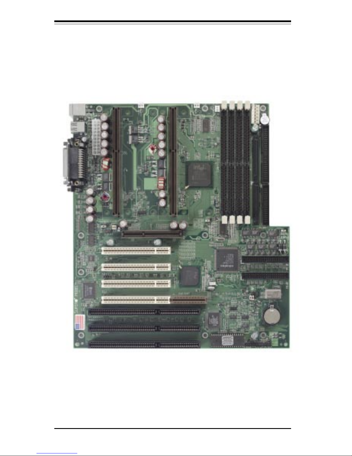
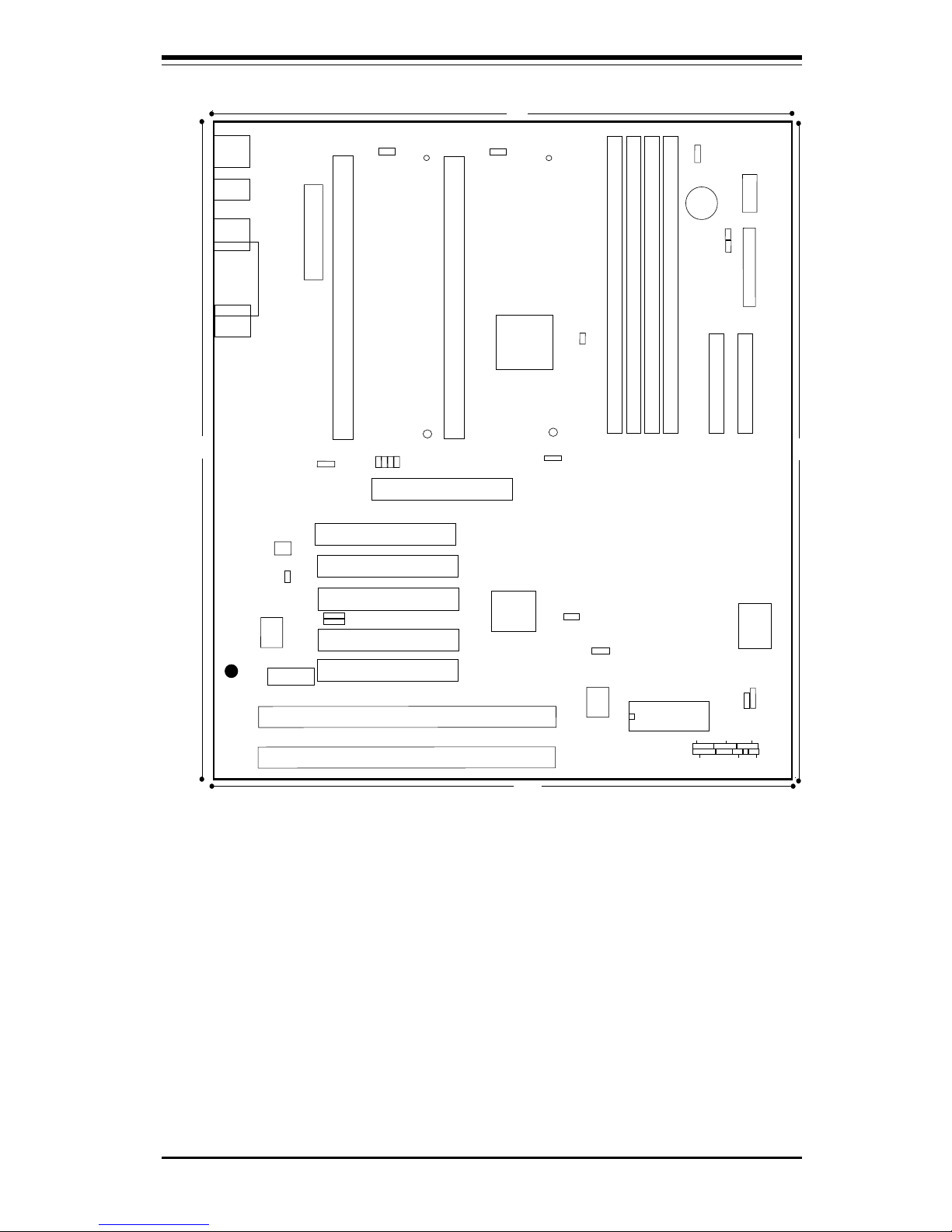
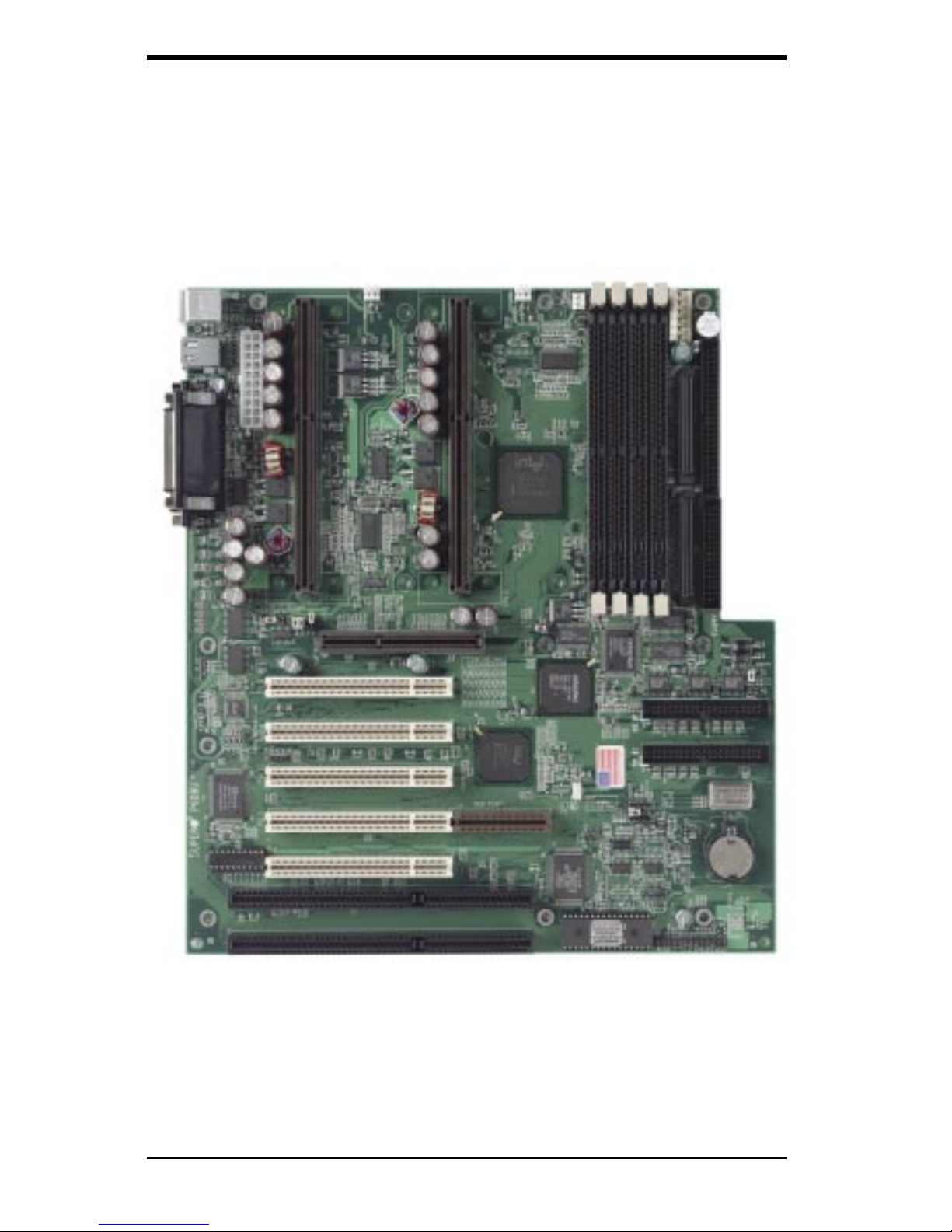
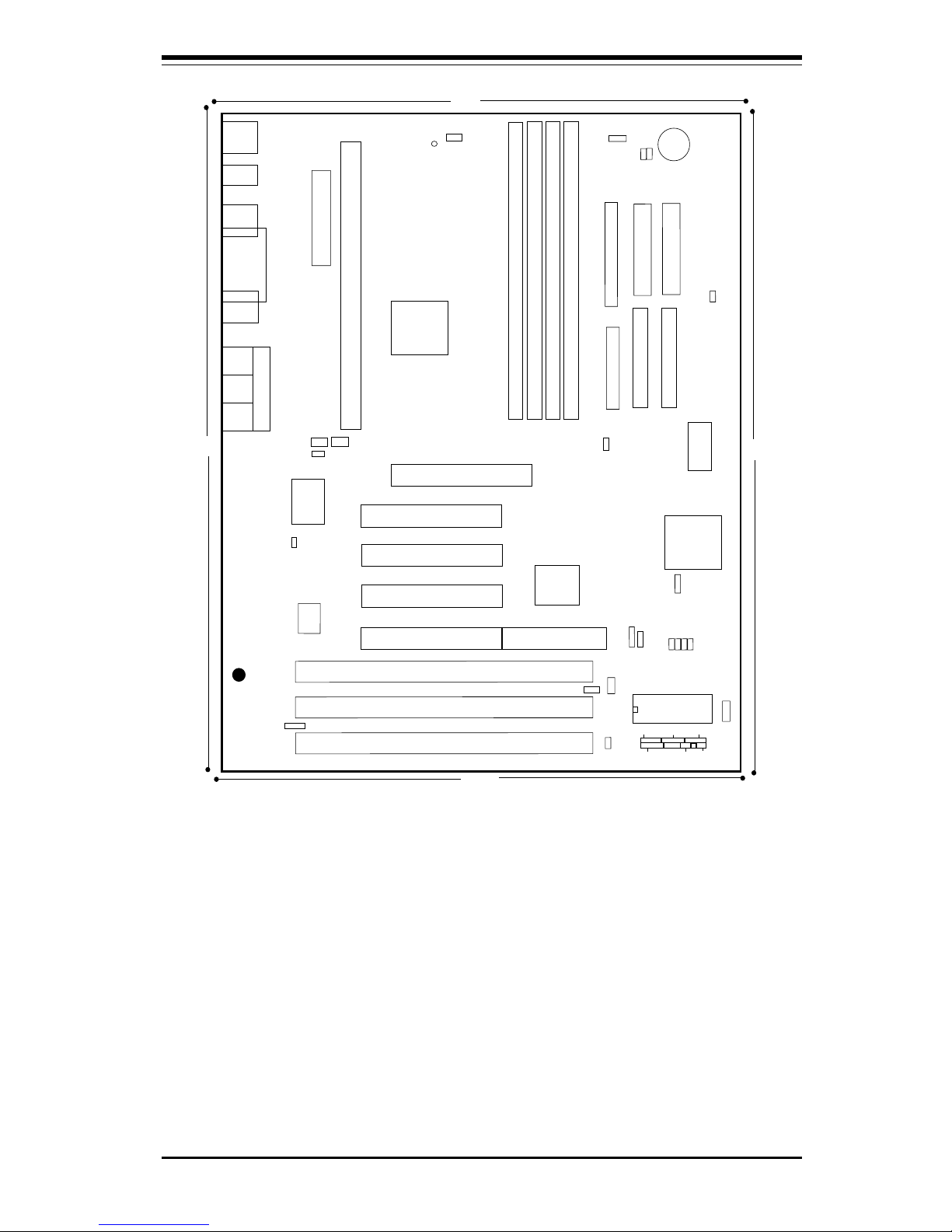
SUPER P6DGS
Figure 1-1. SUPER P6DGS/P6DBS Motherboard Picture
(Both boards share the same PCB)
Chapter 1: Introduction
1-3
®
J21
COM2
J20
COM1
J34
PS/2 KB
(bottom)
PS/2 MOUSE
(top)
J32
ATX POWER
J9
J11
J12
1
J10
PW_ON
RESET
JF1
IDE LED/KEYLOCK/SPEAKER
IR CON
JF2
B
ank3
FLO
PP
Y
U38
U14
J8
1
J17, J18
USB
CPU 1
FAN
J2
J1
1
CPU 2
FAN
JT2
JT1
U2
Bank0
B
ank1
B
ank2
JT3
1
J22
1
SCSI
JA1
1
BIOS
JBT2
JBT1
JA6
1
BT2
B
A
T
T
E
R
Y
+
-
1
S-LED
WOL
UA1
JA4
PCI 1
PCI 2
PCI 3
PCI 4
RAID PORT
U48
JL1
Chassis
Intrusion
A
G
P
P
O
R
T
1
JP20
JB
1
JB2
JB3
JB4
U37
U15
JA5
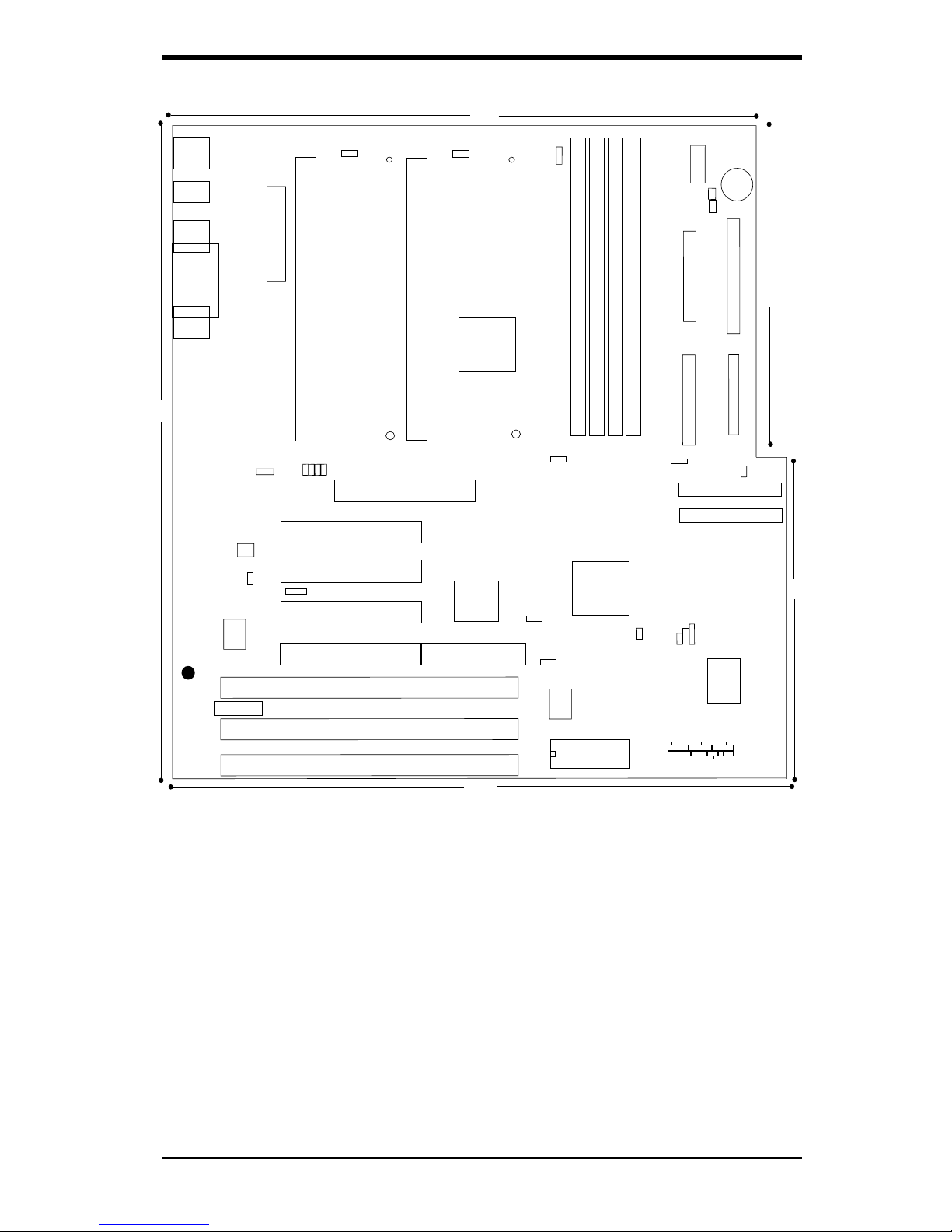
JA5, JA6:SCSI Termination
JBT1: CMOS Clear
JBT2: Ext Battery
JP11
UW SCSI
——–—— Jumper Settings —–——————
JBT1: 1-2 (default)
2-3 CMOS Clear
* To clear the CMOS completely,
disconnect the power source.
JL1: OFF (default)
ON (intrusion)
JP11: 1-2 Auto (default)
2-3 66 MHz
OFF 100 MHz
JP20: 1-2 PIIX CTL PD State
2-3 BIOS CTL PD State (default)
WOL: Wake-on-LAN
——–———————–——–—–——–——–—
JTM
PIIX4
GX
J19
Parallel
Port
Figure 1-2. SUPER P6DGS Motherboard Layout
SUPER P6DGS
————— CPU Core/Bus Ratio –—————
JB1 JB2 JB3 JB4
x3 ON OFF ON ON
x3.5 OFF OFF ON ON
x 4 ON ON O FF ON
x4.5 OFF ON OFF ON
x 5 ON OFF OFF ON
x5.5 OFF OFF OFF ON
x 6 ON ON ON OFF
X6.5 OFF ON ON OFF
x7 ON OFF ON OFF
x7.5 OFF OFF ON OFF
——–—–————————————————
*Note: To Enable the Overheat Buzzer place a
jumper on BZ_On.
6"
6"
12"
9.65"
10.65"
ID
E
1
J15
1
IDE 2
J16
1
JA2
1
UW SCSI
BZ_ON
JOH
Overheat LED
PWR_SEC
1
J36
BZ
1
JA3
1
JA7
1
JP18
J13
J14
JJ14
SBLINK
1
ISA
ISA
ISA
CPU
CPU
Note: Some CPU Core/Bus ratios cannot be
selected for processors that have fixed ratios.
SUPER P6DGS/P6DGE/P6DGU/P6SGU Manual
1-4
SUPER P6DGE
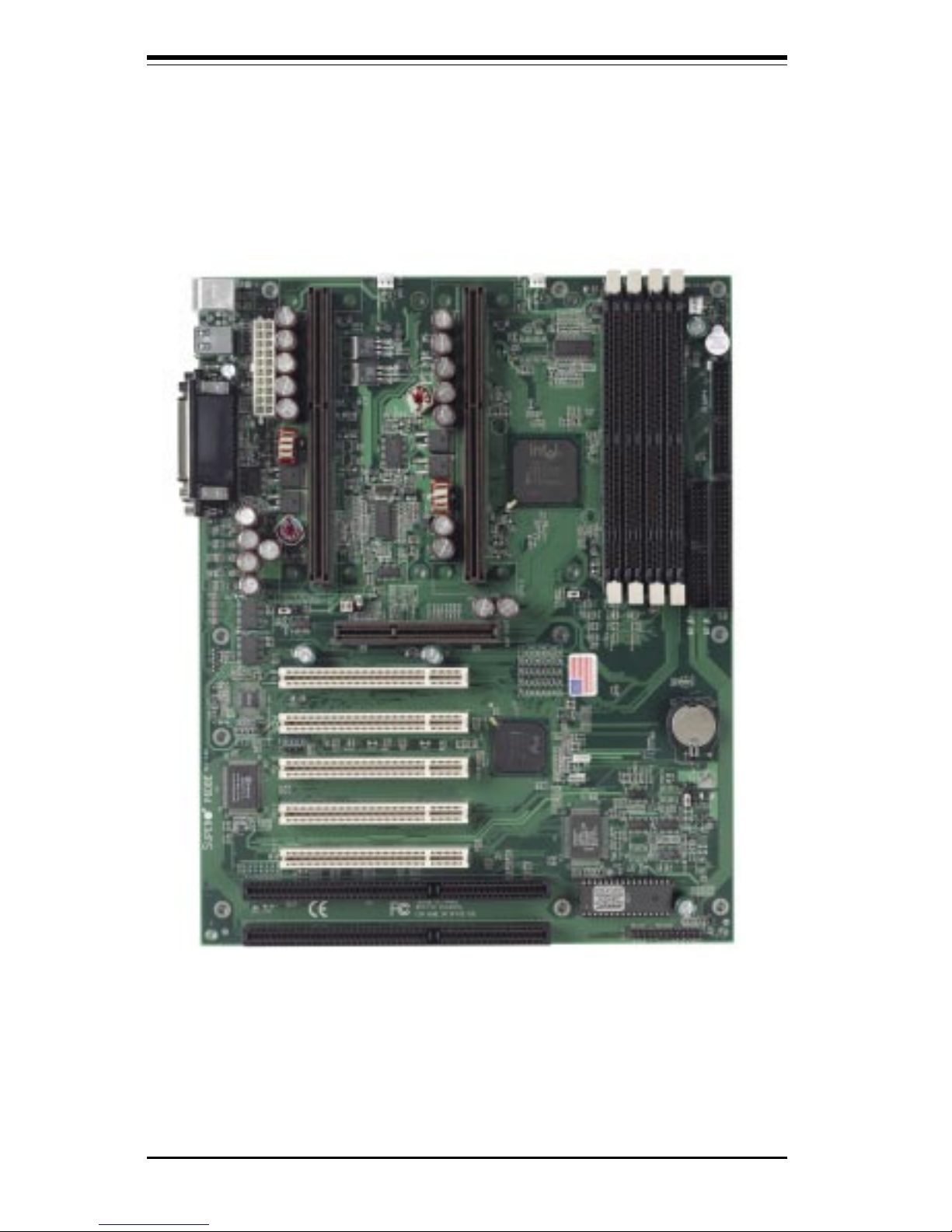
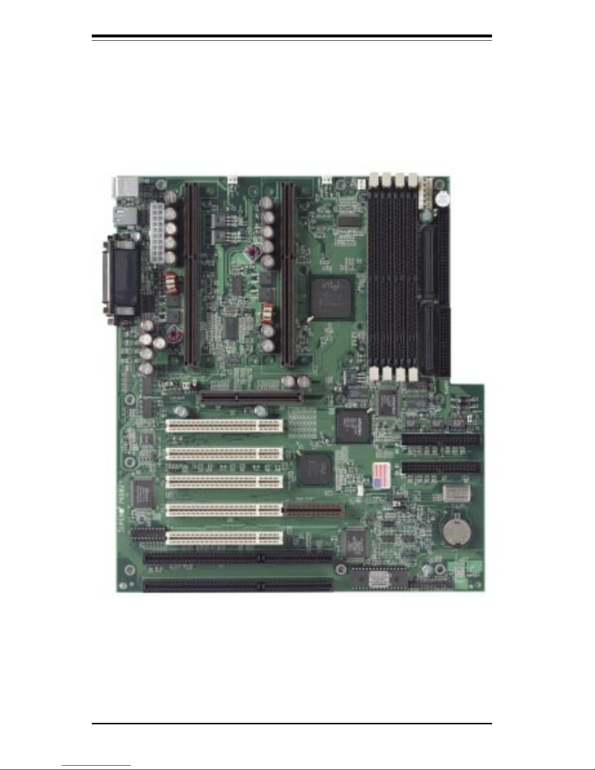
Figure 1-3. SUPER P6DGE/P6DBE Motherboard Picture
(Both boards share the same PCB)
Chapter 1: Introduction
1-5
®
J19
Parallel
Port
J21
COM2
J20
COM1
J13
J32
ATX POWER
PW_ON
RESET
JF1
IDE LED/KEYLOCK/SPEAKER
IR CON
JF2
B
ank3
IDE 2
ID
E
1
FLO
PP
Y
U38
U14
J8
1
J17,J18
USB
CPU 1
FAN
J2
J1
1
CPU 2
FAN
JT2
JT1
U2
Bank0
B
ank1
B
ank2
JT3
T
herm
a
l
C
o
ntrol F
a
n
1
J15 J16
1
1
BIOS
1
BT2
B
A
T
T
E
R
Y
+
-
1
WOL
PCI 1
PCI 2
PCI 3
PCI 4
U48
JL1
Chassis
Intrusion
A
G
P
P
O
R
T
1
JP20
JB
1
JB2
JB3
JB4
U37
U15
JBT1: CMOS Clear
JBT2: Ext Battery
JP11
——–—— Jumper Settings —–——————
JBT1: 1-2 (default)
2-3 CMOS Clear
To clear the CMOS completely,
disconnect the power source.
JL1: OFF (default)
ON (intrusion)
JP11: 1-2 Auto (default)
2-3 66 MHz
OFF 100 MHz
JP20: 1-2 PIIX CTL PD State
2-3 BIOS CTL PD State (default)
WOL: Wake-on-LAN
——–—–——————–———–——–——–—
GX
PIIX4
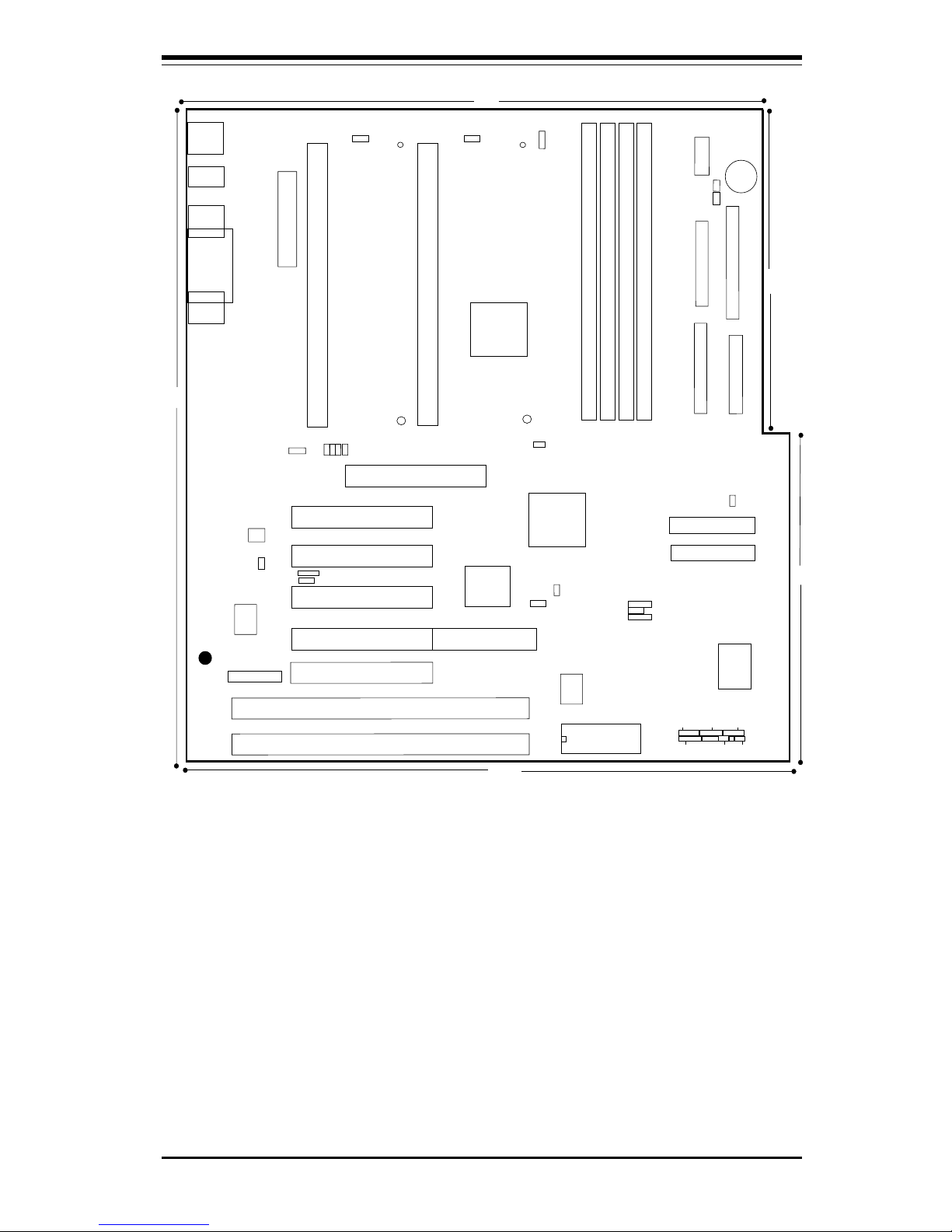
Figure 1-4. SUPER P6DGE Motherboard Layout
SUPER P6DGE
*Note: To Enable the Overheat Buzzer place a
jumper on BZ_On.
J22
BZ_ON
JP16
JB
T
2
JBT1
JP18
PCI 5
J35
J9
J10
J11
J12
BZ
PWR_SEC
J14
9.6"
9.6"
12" 12"
J36
1
JOH1: Overheat LED
JOH1
1
SBLINK
1
JL2
1
1
JTM
ISA
ISA
CPU
CPU
J34
PS/2 KB
(bottom)
PS/2 MOUSE
(top)
Note: Some CPU Core/Bus ratios cannot be
selected for processors that have fixed ratios.
————— CPU Core/Bus Ratio –—————
JB1 JB2 JB3 JB4
x3 ON OFF ON ON
x3.5 OFF OFF ON ON
x 4 ON ON O FF ON
x4.5 OFF ON OFF ON
x5 ON OFF OFF ON
x5.5 OFF OFF OFF ON
x 6 ON ON ON OFF
X6.5 OFF ON ON OFF
x7 ON OFF ON OFF
x7.5 OFF OFF ON OFF
——–—–————————————————
SUPER P6DGS/P6DGE/P6DGU/P6SGU Manual
1-6
SUPER P6DGU
Figure 1-5. SUPER P6DGU/P6DBU Motherboard Picture
(Both boards share the same PCB)
Chapter 1: Introduction
1-7
Figure 1-6. SUPER P6DGU Motherboard Layout
®
J21
COM2
J20
COM1
J14
J13
J32
ATX POWER
J9
J11
J12
J10
PW_ON
RESET
JF1
IDE LED/KEYLOCK/SPEAKER
IR CON
JF2
B
ank3
U38
U14
J8
1
J17,J18
USB
CPU 1
FAN
J2
J1
1
CPU 2
FAN
JT2
JT1
U2
Bank0
B
ank1
B
ank2
SCSI
JA1
BIOS
BT2
B
A
T
T
E
R
Y
+
-
UA1
JA3
PCI 2
PCI 3
PCI 4
PCI 5
RAID PORT
U48
JL1
Chassis
Intrusion
A
G
P
P
O
R
T
U37
U15
JBT1: CMOS Clear
JBT2: Ext Battery
JP11
UW SCSI
Ultra2 LVD/SE
SUPER P6DGU
——–—— Jumper Settings —–——————
JBT1: 1-2 (default)
2-3 CMOS Clear
* To clear the CMOS completely,
disconnect the power source.
JL1: OFF (default)
ON (intrusion)
JP11: 1-2 Auto (default)
2-3 66 MHz
OFF 100 MHz
JP2 0 : 1-2 PIIX CTL PD State
2-3 BIOS CTL PD State (default)
WOL: Wake-on-LAN
S-TERM: On: SCSI Termination Enable
Off: Termination Disable
——–———————–——–—–——–——–—
PIIX4
GX
J19
Parallel
Port
J35
SBLINK
1
JL2
1
JTM
JB4
JB3
JB2
J
B
1
JP20
1
1
WOL
JP18
1
JA5,JA6:SCSI Termination
J16
J15
IDE 2
ID
E
1
1
1
1
FLO
PPY
J22
1
JBT1
JB
T2
SLED
S
-TE
R
M
*Note: To Enable Overheat Buzzer place a jumper on
BZ_On.
6"
6"
12"
10.65"
9.65"
JT3
T
he
rm
al
C
o
ntro
l
F
an
1
JA3
1
JA2
BZ_ON
JOH1
PWR_SEC
1
J36
BZ
1
*Note: JA3 is optional
PCI 1
ISA
ISA
JOH1: Overheat LED
J34
PS/2 KB
(bottom)
PS/2 MOUSE
(top)
Note: Some CPU Core/Bus ratios cannot be
selected for processors that have fixed ratios.
————— CPU Core/Bus Ratio –—————
JB1 JB2 JB3 JB4
x3 ON OFF ON ON
x3.5 OFF OFF ON ON
x 4 ON ON O FF ON
x4.5 OFF ON OFF ON
x 5 ON OFF OFF ON
x5.5 OFF OFF OFF ON
x 6 ON ON ON OFF
X6.5 OFF ON ON OFF
x7 ON OFF ON OFF
x7.5 OFF OFF ON OFF
——–—–————————————————
SUPER P6DGS/P6DGE/P6DGU/P6SGU Manual
1-8
SUPER P6SGU
Figure 1-7. SUPER P6SGU Motherboard Picture
(OEM board only)
Chapter 1: Introduction
1-9
Figure 1-8. SUPER P6SGU Motherboard Layout
®
J21
COM2
J20
COM1
J32
ATX POWER
J9
J11
J12
J10
B
ank3
U14
J8
1
J17,J18
USB
CPU FAN
J1
JT1
U2
Bank0
B
ank1
B
ank2
JA4
PCI 1
PCI 2
PCI 3
PCI 4
RAID PORT
A
G
P
P
O
R
T
U56
SUPER P6SGU
JF1
JF2
U38
IR CON PW_ON
RESET
BIOS
IDE LED/KEYLOCK/SPEAKER
1
J22 J16
1
1
UW SCSI
SCSI
FLOPPY
IDE 2
ID
E
1
1
1
JA1
JA2
1
1
JA3
J15
BZ_ON
JOH1
JOH1: Overheat LED
JT
3
: T
herm
al C
on
trol F
an
JA5,JA6: SCSI Termination
JTM1
1
WOL
JBT2
JP11
JBT1: CMOS Clear
JBT2: Ext Battery
——–—— Jumper Settings —–—————
JBT1: 1-2 (default)
2-3 CMOS Clear
To clear the CMOS completely,
disconnect the power source.
JL1: OFF (default)
ON (intrusion)
JP11: 1-2 Auto (default)
2-3 66 MHz
OFF 100 MHz
JP2 0 : 1-2 PIIX CTL PD State
2-3 BIOS CTL PD State (default)
WOL: Wake-on-LAN
S-TERM: On: SCSI Termination Enable
Off: Termination Disable
——–———–————–———–——–——–
*Note: To Enable the Overheat Buzzer
place a jumper on BZ_On.
BZ
JT3
PIIX4
GX
J19
Parallel
Port
UA10
JB1
JB2
JB3
JB4
1
JBT1
1
JP20
1
3860
JT2
1
SCSI LED
JL1
S-TERM
J37
J44
ESS
1938
7890
JJ14
J14
J13
1
JPSI
Ultra2 LVD/SE
12"
12"
8.875"
8.875"
J39
J35
*Note: JA4 is optional
ISA
ISA
ISA
MIC
IN
LINE
IN
LINE
OUT
C
PU
J34
PS/2 KB
(bottom)
PS/2 MOUSE
(top)
Note: Some CPU Core/Bus ratios cannot be
selected for processors that have fixed ratios.
————— CPU Core/Bus Ratio –—————
JB1 JB2 JB3 JB4
x 3 ON OFF ON ON
x3.5 OFF OFF ON ON
x 4 ON ON O FF ON
x4.5 OFF ON OFF ON
x5 ON OFF OFF ON
x5.5 OFF OFF OFF ON
x 6 ON ON ON OFF
X6.5 OFF ON ON OFF
x7 ON OFF ON OFF
x7.5 OFF OFF ON OFF
——–—–————————————————
SUPER P6DGS/P6DGE/P6DGU/P6SGU Manual
1-10
CPU
440GX
CPU
AGP
Port
IO
APIC
PIIX4
Power
Mana
g
ement
SDRAM
Host Bus
PCI Slots
SMBus
USB
Ports
IDE Ports
ISA Slots
BIOS
SIO
SCSI
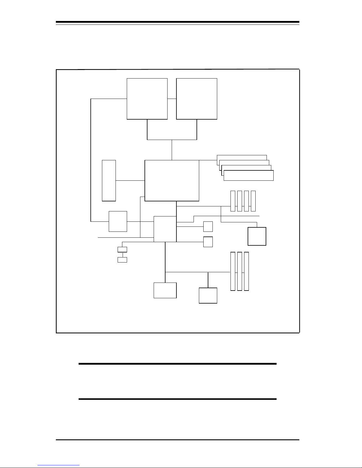
Figure 1-9. 440GX AGP Chipset:
System Block Diagram (Dual Processors)
Note: This is a general block diagram and may not represent the
actual number of slots/CPUs on your motherboard. See the
following page for the actual specifications of each board.
Chapter 1: Introduction
1-11
Features of the P6DGS, P6DGE, P6DGU and P6SGU
The following list covers the general features of the SUPER P6DGS, P6DGE,
P6DGU and P6SGU.
CPU
• Single or dual Pentium II 233/266/300/333 MHz processors at 66 MHz
bus speed or Pentium II/III 350/400/450/500/550/600/650/700 MHz
processors at 100 MHz bus speed (The P6SGU supports only a single Pentium II/
III processor.) Note: Please refer to the support section of our web site for a complete listing
of supported processors. (http://www.supermicro.com/TechSupport.htm)
Memory
• 2 GB unbuffered 3.3V SDRAM or 2 GB registered SDRAM
(Note: When the CPU bus is running at 100 MHz, the SDRAM must be PC-100 compliant
DIMMs.)
(Note: The maximum cacheable memory size depends on processor capabilities.)
• ECC (Error Checking and Correction), non-ECC and Error Checking
supported
Chipset
• Intel 440GX
Expansion Slots
P6DGS/P6SGU P6DGU/P6DGE
• 4 PCI slots • 5 PCI slots
• 3 ISA slots • 2 ISA slots
[one PCI/ISA shared slot] [one PCI/ISA shared slot]
• 1 AGP slot • 1 AGP slot
BIOS
• 2 Mb AMI® Flash BIOS
• APM 1.2, DMI 2.01, Plug and Play (PnP)
• Adaptec 7890 SCSI BIOS (P6DGU/P6SGU only)
• Adaptec 7895 SCSI BIOS (P6DGS only)
PC Health Monitoring
• Seven onboard voltage monitors for CPU core(s), CPU I/O, +3.3V, ±5V,
and ±12V
• Three fans status monitor with firmware/software on/off control
• Environmental temperature monitor and control
• CPU fan auto-off in sleep mode
• Chassis overheat alarm, LED, and control
• Chassis intrusion detection
• System resource alert

SUPER P6DGS/P6DGE/P6DGU/P6SGU Manual
1-12
• Hardware BIOS virus protection
• Auto-switching voltage regulator for the CPU core
• SUPERMICRO SUPER Doctor and (optional) Intel® LANDesk® Client
Manager (LDCM) support
ACPI/PC 98 Features
• Microsoft OnNow
• Slow blinking LED for suspend-state indicator
• BIOS support for USB keyboard
• Real time clock wake-up alarm
• Main switch override mechanism
• External modem ring-on
Onboard I/O
• One 68-pin, 16-bit Ultra2 LVD/SE SCSI connector, one 68-pin, 16 bit
Ultra Wide SCSI Connector and one 50-pin, 8-bit SCSI connector (P6DGU/
P6SGU)
• Dual 68-pin, 16-bit Ultra-Wide SCSI connectors and one 50-pin, 8-bit
SCSI connector (P6DGS)
• RAID port for Adaptec ARO-1130CA/SA RAIDport II card (P6DGS only)
• RAID port for Adaptec ARO-1130U2 RAIDport III card (P6DGU only)
• 2 EIDE Bus Master interfaces support Ultra DMA/33 and Mode 4
• 1 floppy port interface
• 2 Fast UART 16550 serial ports
• EPP (Enhanced Parallel Port) and ECP (Extended Capabilities Port)
parallel port
• PS/2 mouse and PS/2 keyboard
• Infrared port
• 2 USB (Universal Serial Bus) ports
• Solo-1 PCI
Audio
Drive
®
(P6SGU only)
CD Utilities
• Intel LANDesk Client Manager for Windows NT® and Windows® 95/98
(optional)
• PIIX4 Upgrade Utility for Windows 95/98
• BIOS Flash Upgrade Utility
• SUPER Doctor Utility
• SCSI Utility, manual and driver
Dimensions
• SUPER P6DGS - ATX (12" x 9.65") * See board diagram for full measurements
• SUPER P6DGE - ATX (12" x 9.6")
• SUPER P6DGU - ATX (12" x 9.65") * See board diagram for full measurements
• SUPER P6SGU - ATX (12" x 8.875")

Chapter 1: Introduction
1-13
1-2 Chipset Overview
The 440GX chipset, developed by Intel, is the ultimate processor platform targeted for 3D graphics and multimedia applications. Along with System-to-PCI
bridge integrated with optimized DRAM controller and data path, the chipset
introduces the Accelerated Graphics Port (AGP) interface. AGP is a high performance, component level interconnect targeted at 3D applications and is based
on a set of performance enhancements to PCI. The I/O subsystem portion of the
440GX platform is based on the PIIX4, a highly integrated version of Intel's PCIto-ISA bridge family.
The PCI/AGP and system bus interface controller (82443GX) supports up to two
Pentium II/III processors. It provides an optimized 72-bit DRAM interface (64-bit
data plus ECC). This interface supports 3.3V DRAM technology. The controller
provides the interface to a PCI bus operating at 33 MHz. This interface implementation is compliant with the PCI Rev 2.1 Specification. The AGP interface
is based on AGP Specification Rev 1.0. It can support data transfer rates of up
to 133 MHz (532 MB/s).
1-3 PC Health Monitoring
This section describes the PC health monitoring features of the SUPER P6DGS,
P6DGE, P6DGU and P6SGU. All have an onboard System Hardware Monitor
chip that supports PC health monitoring.
Seven Onboard Voltage Monitors for the CPU Core(s),
CPU I/O, +3.3V,
±±
±±
±5V,
and
±±
±±
±12V
The onboard voltage monitor will scan the seven monitored voltages continuously.
Once a voltage becomes unstable, it will report a warning or an error message
onscreen. Users can adjust the threshold of the monitored voltage to determine
the sensitivity of the voltage monitor.
Three-Fan Status Monitor with Firmware/Software On/Off
Control
The PC health monitor can check the RPM status of the cooling fans. The
onboard 3-pin CPU fan is controlled by the ACPI BIOS and the ACPI enabled
operating system. The thermal fans are controlled by the overheat detection
logic.

SUPER P6DGS/P6DGE/P6DGU/P6SGU Manual
1-14
Environmental Temperature Control
The thermal control sensor monitors the real-time CPU temperature. It will
turn on a back-up fan whenever the CPU temperature exceeds a userdefined threshold. The overheat circuitry runs independently from the CPU.
It can continue to monitor for overheat conditions even if the CPU is in sleep
mode. Once it detects that the CPU temperature is too high, it will automatically turn on the back-up fan to prevent any overheat damage to the CPU.
The onboard chassis thermal circuitry can monitor the overall system temperature and alert users when the chassis temperature is too high.
CPU Fan Auto-Off in Sleep Mode
The CPU fan will turn on when the power is on. It can be turned off when
the CPU is in sleep mode. When the CPU is in sleep mode it does not run at
full power, and therefore generates less heat. For power saving purposes,
the user has the option to shut down the CPU fan at such times.
CPU Overheat Alarm, LED and Control
This feature is available when the user enables the CPU overheat warning
function in the BIOS. The overheat alarm will activate when the CPU temperature exceeds a temperature defined by the user. When the overheat
alarm is activated both the overheat fan and the LED are triggered.
Chassis Intrusion Detection
The chassis intrusion circuitry can detect unauthorized intrusion to the system. The chassis intrusion connector is located on JL1. Attach a microswitch to JL1. When the micro-switch is closed, it means that the chassis
has been opened. The circuitry will then alert the user with a warning
message when the system is turned on. This feature is available when the
user is running Intel's LANDesk Client Manager, and SUPERMICRO's Super
Doctor.
System Resource Alert
This feature is available when used with Intel's LANDesk Client Manager
(optional). The user can be notified of certain system events. For example,
if the system is running low on virtual memory, the hard drive space is not
enough to save the data, you are then alerted of the potential problems.

Chapter 1: Introduction
1-15
Hardware BIOS Virus Protection
The system BIOS is protected by hardware so that no virus can infect the
BIOS area. The user can only change the BIOS content through the flash
utility provided by SUPERMICRO. This feature can prevent viruses from
infecting the BIOS area and destroying valuable data.
Auto-Switching Voltage Regulator for the CPU Core
The switching voltage regulator for the CPU core can support up to 20A of
current, with auto-sensing voltage ID ranging from 1.8V to 3.5V. This will
allow the regulator to run cooler and makes the system more stable.
Intel LANDesk® Client Manager (LDCM) Support
As the computer industry evolves, PC systems become more complex and
harder to manage. Historically, only experts have been able to fully understand and control these complex systems. Today's users want manageable
systems that they can interact with automatically. Client Manager enables
both administrators and clients to:
• Review system inventory
• View DMI-compliant component information
• Back-up and restore system configuration files
• Troubleshoot
• Receive notification of system events
• Transfer files to and from client workstations
• Remotely reboot client workstations
1-4 Solo-1TM PCI
Audio
Drive
®
(Optional for P6SGU)
The Solo-1 PCI
Audio
Drive solution implements a single chip PCI audio solution,
providing high-quality audio processing while maintaining full legacy DOS game
compatibility. With a dynamic range over 80 dB, the Solo-1 complies with the
Microsoft PC 97/PC 98 specifications and meets WHQL audio requirements.
The Solo-1 incorporates a microcontroller, ESFM
TM
music synthesizer, 3-D stereo effects processor, 16-bit stereo wave ADC and DAC, 16-bit stereo music
DAC, MPU-401 UART mode serial port, dual game port, hardware master volume
control, a serial port interface to external wavetable music synthesizer, DMA
control logic with FIFO, and PCI bus interface logic. There are three stereo
inputs (LINE-IN, LINE-OUT, MIC IN) and a mono microphone input.

SUPER P6DGS/P6DGE/P6DGU/P6SGU Manual
1-16
1-5 ACPI/PC 98 Features
ACPI stands for Advanced Configuration and Power Interface. The ACPI
specification defines a flexible and abstract hardware interface that provides a standard way to integrate power management features throughout
a PC system, including hardware, operating system and application software. This enables the system to automatically turn on and off peripherals
such as CD-ROMs, network cards, hard disk drives and printers.
In addition to enabling operating system-directed power management, ACPI
provides a generic system event mechanism for Plug and Play and an operating system-independent interface for configuration control. ACPI leverages the Plug and Play BIOS data structures while providing a processor
architecture-independent implementation that is compatible with Windows98.
In order to enable ACPI, the default APM mode must be disabled in BIOS
(see page 5-12). To install Windows 98 with ACPI, enter DOS and type
"setup /p j" at the CDROM prompt (usually D:\) with the Windows98 CD
loaded. (Make sure you include the spaces after "setup" and "p".) Then hit
<Enter>. You can check to see if ACPI has been properly installed by
looking for it in the Device Manager, which is located in the Control Panel in
Windows.
Microsoft OnNow
The OnNow design initiative is a comprehensive, system-wide approach to
system and device power control. OnNow is a term describing a PC that is
always on but appears to be off and that responds immediately to users
and requests.
Slow Blinking LED for Suspend State Indicator
When the CPU goes into a suspend state, the power LED will start blinking
to indicate that the CPU is in suspend mode. When the user presses any
key, the CPU will wake-up and the LED will automatically stop blinking and
remain on.
BIOS Support for USB Keyboard
If a USB keyboard is the only keyboard in the system, it will function like a
normal keyboard during system boot-up.

Chapter 1: Introduction
1-17
Real Time Clock Wake-Up Alarm
The PC may appear to be off when not in use, but it is still capable of
responding to preset wake-up events. The user can set a timer in the BIOS
to wake-up the system at a predetermined time.
Main Switch Override Mechanism
When an ATX power supply is used, the power button can function as a
system suspend button. When the user presses the power button, the
system will enter a SoftOff state. The monitor will be suspended and the
hard drive will spin down. Pressing the power button again will cause the
whole system to wake-up. During the SoftOff state, the ATX power supply
provides power to keep the required system circuitry alive. In case the
system malfunctions and you want to turn off the power, just depress the
power button for 4 seconds. The system will turn off and no power will be
provided to the motherboard.
External Modem Ring-On
An external modem ringing can be used to trigger a wake-up when the
system is in the SoftOff state .
Wake-On-LAN (WOL)
Wake-on-LAN is defined as the ability of a management application to remotely power up a computer that has been powered off. Remote PC setup,
updates and asset tracking can occur after hours and on weekends so that
daily LAN traffic is kept to a minimum and users are not interrupted.
The motherboards have a 3-pin header (WOL) used to connect to the 3-pin
header on a Network Interface Card (NIC) that has WOL capability. Note
that Wake-on-Lan can only be used with an ATX 2.01 (or above) compliant
power supply.
1-6 Power Supply
As with all computer products, a stable power source is necessary for
proper and reliable operation. It is even more important for Pentium II/III
CPUs that have high clock rates.

SUPER P6DGS/P6DGE/P6DGU/P6SGU Manual
1-18
The SUPER P6DGS/P6DGE/P6DGU/P6SGU accommodates ATX power supplies. Although most power supplies generally meet the specifications required
by the CPU, some power supplies are inadequate.
It is highly recommended that you use a high quality power supply that
meets ATX power supply specification 2.01. Additionally, in areas where
noisy power transmission is present, you may choose to install a line filter
to separate noise from the computer. You can also install a power surge
protector to help avoid problems caused by power surges.
1-7 Super I/O
The disk drive adapter functions of Super I/O chip include a floppy disk
drive controller compatible with industry standard 82077/765, a data separator, write pre-compensation circuit, decode logic, data rate selection, a
clock generator, drive interface control logic and interrupt and DMA logic.
The wide range of functions integrated into the Super I/O greatly reduces
the number of components required for interfacing with floppy disk drives.
The Super I/O supports four 360 K, 720 K, 1.2 M, 1.44 M or 2.88 M disk
drives and data transfer rates of 250 Kb/s, 500 Kb/s or 1 Mb/s.
The Super I/O provides two high-speed serial communication ports (UARTs),
one of which supports serial infrared communication. Each UART includes
a 16-byte send/receive FIFO, a programmable baud rate generator, complete modem control capability and a processor interrupt system. Both
UARTs provide legacy speed with baud rate up to 115.2 Kbps and also
advanced speed with baud rates of 230 K, 460 K, or 921 Kbps which
support higher speed modems.
The Super I/O supports one PC-compatible printer port (SPP), Bi-directional
Printer Port (BPP) and also Enhanced Parallel Port (EPP) and Extended Capabilities Port (ECP). Also available, through the printer port interface pins, are:
Extension FDD Mode and Extension 2FDD Mode allowing one or two external
floppy disk drives to be connected.
The Super I/O provides functions that comply with ACPI (Advanced Configuration
and Power Interface), which includes support of legacy and ACPI power management through SMI or SCI function pins. It also has auto power management to
reduce power consumption.
The Super I/O complies with Microsoft PC97 Hardware Design Guide. IRQs,
DMAs and I/O space resources are flexible to meet ISA PnP requirements.
Moreover, it meets the specifications of PC97's power management requirements: ACPI and DPM (Device Power Management).

Chapter 1: Introduction
1-19
1-8 AIC-7895 MultiChannel
TM
Single-Chip Ultra SCSI
The SUPER P6DGS has an onboard SCSI controller that is 100% compatible
with all major operating and hardware platforms. PCI 2.1 and SCAM Level 1
compliance are assured. Two independent SCSI channels provide a per channel
data transfer rate of 40 MB/s. Connectors include two 68-pin, 16-bit Ultra Wide
SCSI connectors (JA1/JA2) and a 50-pin, 8-bit SCSI connector (JA3). You can
connect up to 15 devices (seven 8-bit internal and eight 16-bit internal or external
SCSI devices, or 15 Wide internal and external SCSI devices).
When Fast SCSI devices are connected, the total length of all cables (internal
and external) must not exceed 3 meters (9.8 ft) to ensure reliable operation. If
no Fast SCSI devices are connected, the total length of all cables must not
exceed 6 meters (19.7 ft).
The AIC-7895 consolidates the functions of two SCSI chips, eliminating the need
for a PCI bridge. Reducing PCI bus loading enables system capabilities to be
expanded with additional PCI devices.
The AIC-7895 functions with Adaptec RAIDport II (ARO-1130SA/1130CA) to deliver RAID functionality.
1-9 AIC-7890 Ultra2 SCSI Controller
Note: If you are using a low voltage differential Hard Drive, it is recommended you use LVD/
SE Ultra2 SCSI cable. LVD/SE cable offers increased length, and can accommodate more
devices.
The SUPER P6DGU/P6SGU has an onboard SCSI controller that is 100% compatible with all major operating and hardware platforms. The AIC-7890 controller
provides advanced PCI-to-SCSI Ultra2 SCSI host adapter features in a 272-pin
Ball Grid Array (BGA) package, as well as containing an integrated dual mode
(LVD/SE) transceiver. The AIC-7890 Ultra2 SCSI chip connects to a 32-bit PCI
bus. It is PCI 2.1 compliant, fully supports the power management requirements
specified in Microsoft's PC 97 guidelines, and provides SCAM level 2 support.
The AIC-7890 functions with Adaptec RAIDport III (ARO-1130U2) to deliver
RAID functionality.
The AIC-7890 Ultra2 SCSI controller, used together with the AIC-3860 transceiver, allows Ultra2 and single-ended devices to operate together on the same
SCSI bus without inpacting Ultra2 performance and cable lengths. The AIC-7890
 Loading...