

Supermicro Supero C9Z390-CG-IW Quick Reference Manual
C9Z390-CG-IW
a
C9Z390-CG-IW QUICK REFERENCE GUIDE Product Safety Information
!
Standardized Warning Statements
Motherboards
About Standardized Warning Statements
The following statements are industry standard warnings, provided to warn the user of situations which can potentially
cause a bodily injury. Should you have questions or experience difculty, contact Supermicro's Technical Support De-
partment for assistance. Only certied technicians should attempt to install or congure components.
Read this section in its entirety before installing or conguring components in the Supermicro chassis.
WARNING: This product can expose you to chemicals including
lead, known to the State of California to cause cancer and birth
defects or other reproductive harm. For more information, go
to www.P65Warnings.ca.gov.
Battery Handling
Warning!
There is a danger of explosion if the battery is replaced incorrectly. Replace the battery only with the same or an equiva-
lent type recommended by the manufacturer. Dispose of used batteries according to the manufacturer's instructions.
警告
電池更換不當會有爆炸危險。請使用製造商建議之相同或功能相當的電池更換原有電池。請按照製造商的說明指示處理
廢棄舊電池。
警告
电池更换不当会有爆炸危险。请只使用同类电池或制造商推荐的功能相当的电池更换原有电池。请按制造商的说明处理
废旧电池。
電池の取り扱い
電池交換が正しく行われなかった場合、破裂の危険性があります。 交換する電池はメーカーが推奨する型、または同等のもの
を使用下さい。 使用済電池は製造元の指示に従って処分して下さい。
경고!
배터리가 올바르게 교체되지 않으면 폭발의 위험이 있습니다. 기존 배터리와 동일하거나 제조사에서 권장하는 동등한
종류의 배터리로만 교체해야 합니다. 제조사의 안내에 따라 사용된 배터리를 처리하여 주십시오.
Note: For complete product safety information, refer to http://www.supermicro.com/about/policies/safety_information.cfm.
C9Z390-CG-IW QUICK REFERENCE GUIDE
主機板
(Motherboard)
Equipment name
Restricted substances and its chemical symbols
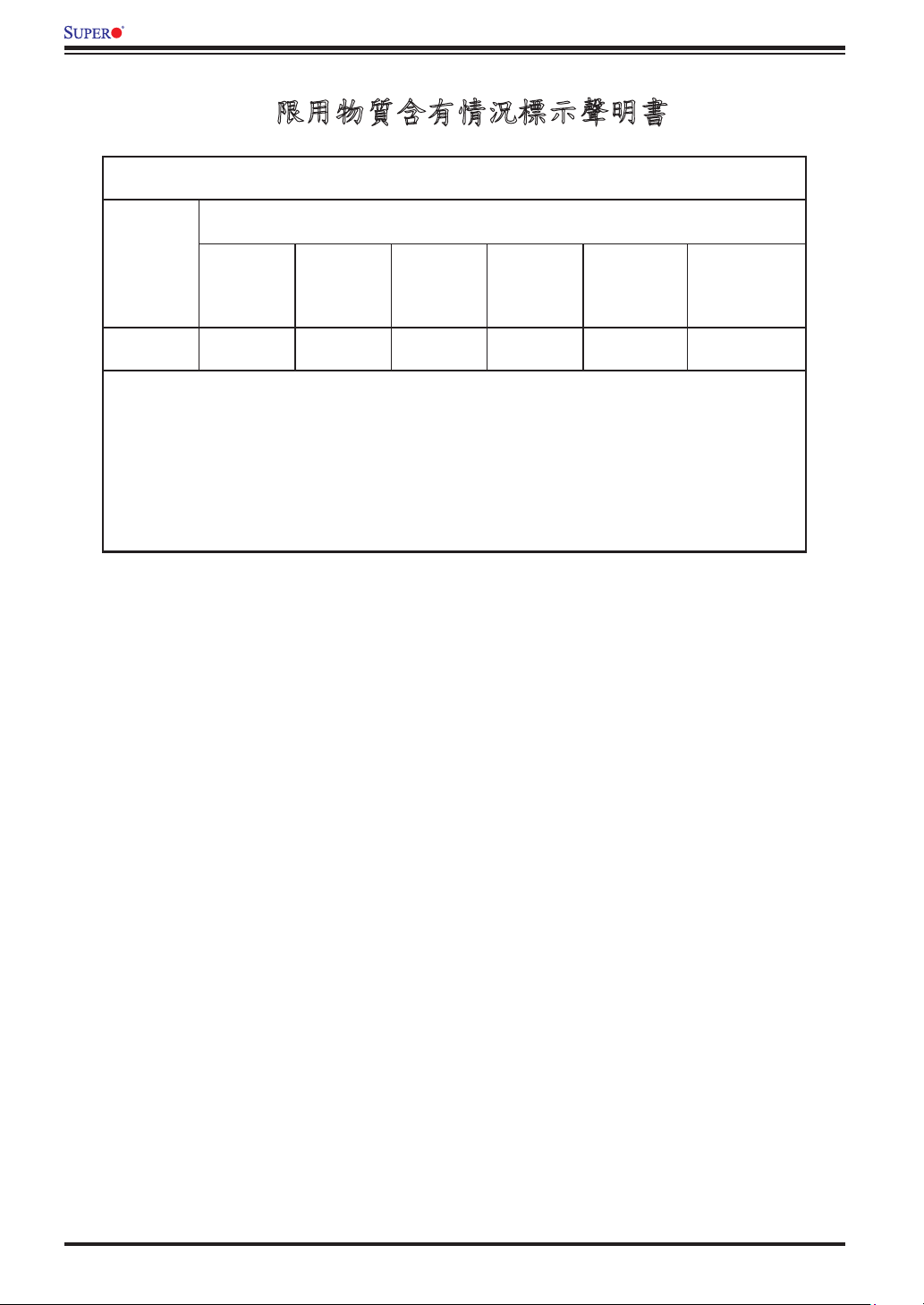
限用物質含有情況標示聲明書
Declaration of the Presence Condition of the Restricted Substances Marking
設備名稱:主機板 / Motherboard
型號(型式):C9Z390-CG-IW
Type designation (Type)
限用物質及其化學符號
限用物質含有情況標示聲明書
單元Unit
鉛Lead
(Pb)
Mercury
汞
(Hg)
Cadmium
鎘
(Cd)
六價鉻
Hexavalent
chromium
(Cr+6)
-
備考1.〝超出0.1 wt %〞及〝超出0.01 wt %〞係指限用物質之百分比含量超出百分比含量基準
值。
Note 1:“Exceeding 0.1 wt %” and “exceeding 0.01 wt %” indicate that the percentage content of the restricted substance exceeds the
reference percentage value of presence condition.
○ ○ ○ ○ ○
多溴聯苯
Polybrominated
biphenyls
(PBB)
多溴二苯醚
Polybrominated
diphenyl ethers
(PBDE)
備考2.〝○〞係指該項限用物質之百分比含量未超出百分比含量基準值。
Note 2:“○” indicates that the percentage content of the restricted substance does not exceed the percentage of reference value of presence.
備考3.〝-〞係指該項限用物質為排除項目。
Note 3:The “−” indicates that the restricted substance corresponds to the exemption.
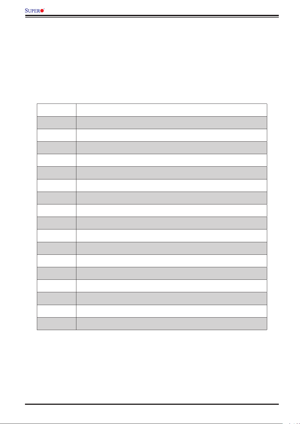
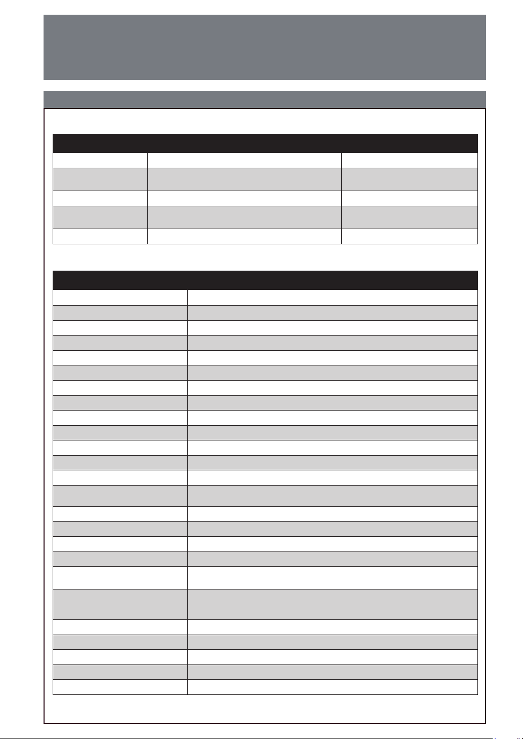
C9Z390-CG-IW QUICK REFERENCE GUIDE BIOS POST Codes
AMI BIOS POST Codes
About AMI BIOS POST Codes
The table below lists some of AMI BIOS POST codes. For more information, refer to https://www.supermicro.com.tw/
manuals/other/AMI_BIOS_POST_Codes_for_Grantley_Motherboards.pdf.
Code Description
0x32 CPU post-memory initialization is started
0x55 No Memory detected or memory failed
0x63 CPU DXE initialization is started
0x69 North Bridge DXE initialization is started
0x70 South Bridge DXE initialization is started
0x92 PCI Bus initialization is started
0x99 Super IO Initialization
0x9A USB initialization is started
0xA0 IDE initialization is started
0xA9 Boot into BIOS setup menu
0xAE Legacy Boot event
0xB2 Legacy Option ROM Initialization
0xB4 USB hot plugged
0xD6 No VGA device
0xD7 No Keyboard plugged in
0xF2 Recovery process started
0xF9 Recovery capsule is not found
C9Z390-CG-IW QUICK REFERENCE GUIDE
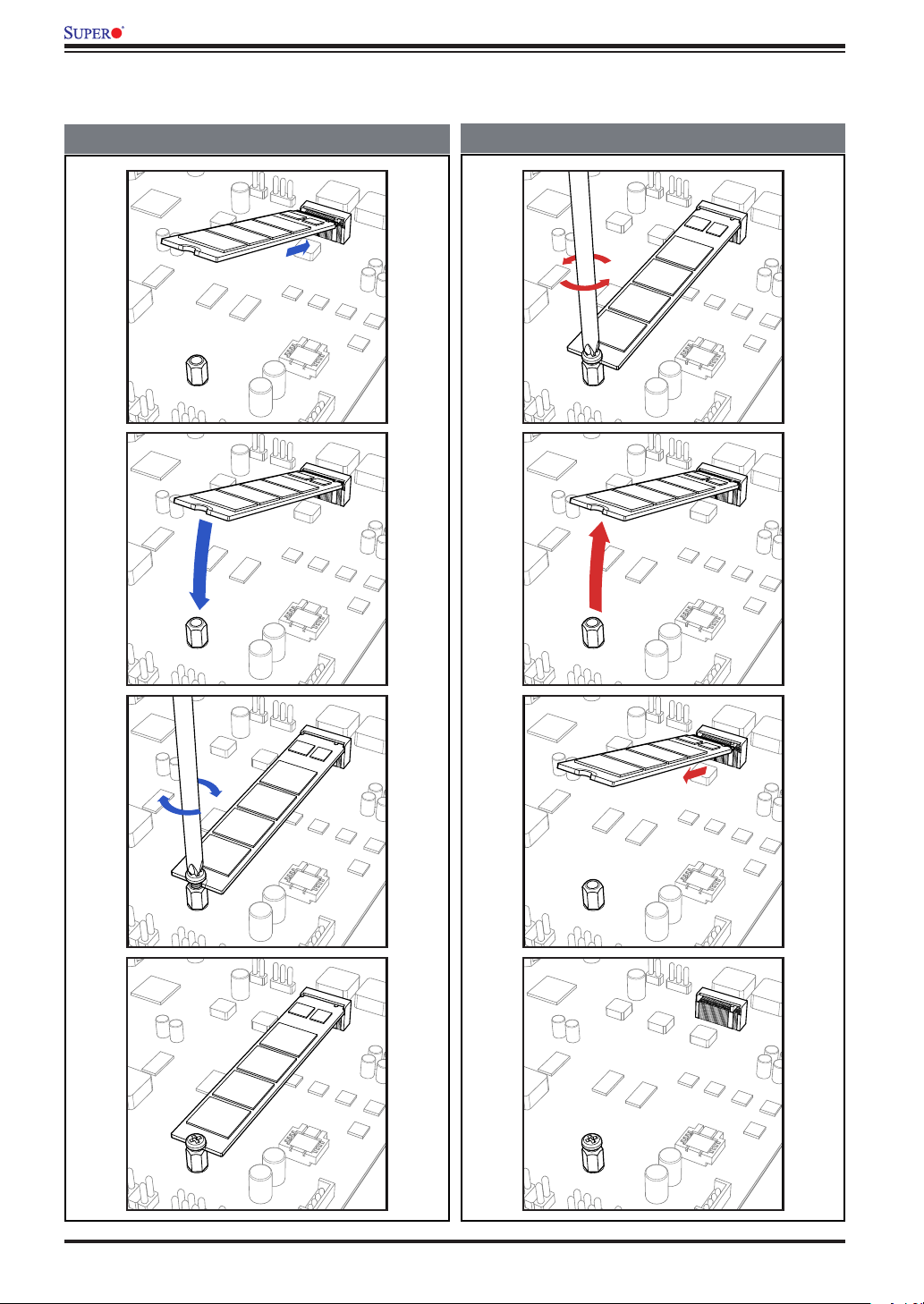
M.2 Device Installation and Removal Instructions
M.2 Device Installation and Removal Instructions
M.2 Device Installation
M.2 Device Removal
C9Z390-CG-IW QUICK REFERENCE GUIDE
Audio Conguration
Audio Conguration
Audio Conguration
LMO
P
Q
Light Blue
O
(Line In/Side Speaker Out)
Lime
P
(Line Out/Front Speaker Out))
L
Orange
(Center/Subwoofer)
M
Black
(Surround)
Q
Pink (Mic In) Mic In Mic In Mic In Mic In
2 Channel 4.1 Channel
5.1 Channel
Line In Line In Line In
Line Out
Front Speaker Out Front Speaker Out Front Speaker Out
Center/Subwoofer Center/Subwoofer
Rear Speaker Out Rear Speaker OutRear Speaker Out
7.1 Channel
Side Speaker Out
C9Z390-CG-IW QUICK REFERENCE GUIDE
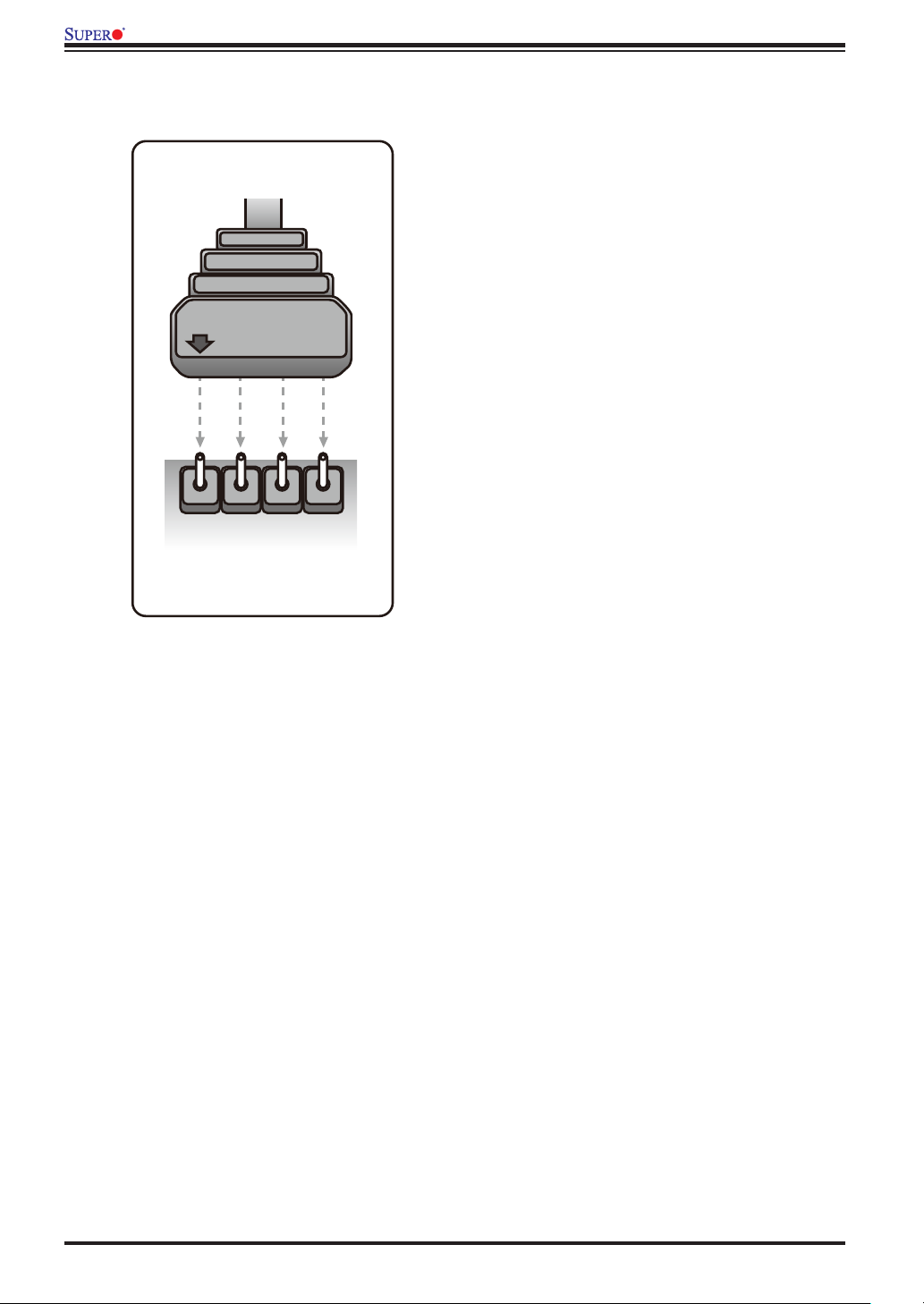
Warning for RGB LED Light Strip Installation
LED Cable
12V GRB
R
G
12V
LED Header
B
Warning for RGB LED Light Strip Installation
Notice:
Please read the following instructions
carefully before connecting the RGB LED
strip to the RGB LED header (JRLED1) on
your motherboard.
Locate an arrow (labeled with 12V) on the
cable connector. Align the arrow with the
12V pin of RGB LED header. Once they are
aligned, carefully install the cable into the
header.
Failure to do so may have no impact on
motherboard functions.
However, improper installation or
misalignment may cause damages to the
RGB LED strip and RGB power parts after
a period of time.
UPERMICR
S
R
C9Z390-CG-IW
Quick RefeRence Guide Rev. 1.0a
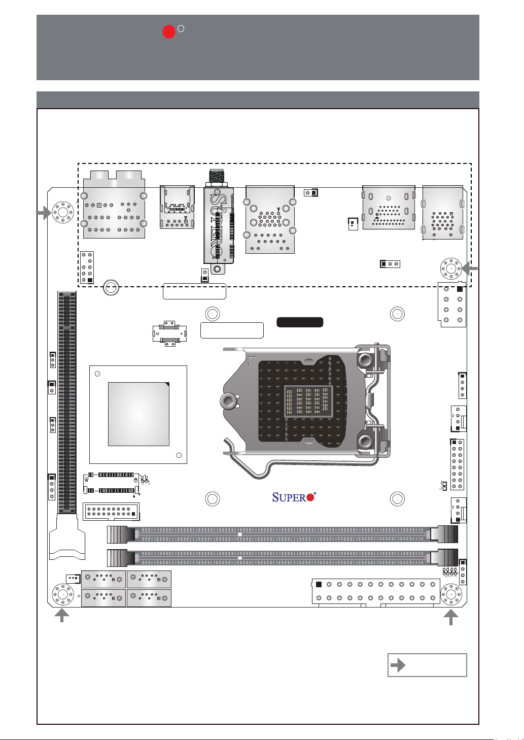
Motherboard Layout and Features
I/O BACK PANEL
JPME2
JL1
JD1JWD1
JSD1
AUDIO FP
HD AUDIO
MH12
CPU SLOT7 PCI-E 3.0 X16
2280
USB 8(3.1)
PCH
PCI-E M.2-M1
LED5
A
A
C C
USB 2/3(3.0)
USB 6/7(3.1)
MAC CODE
LED2
I-SATA3
JCMOS
WIFI+BT
BAR CODE
I-SATA2
PCI-E M.2-E1
JRF1
LAN1
USB 4/5(3.1)
LGA 1151
8th/9th Gen Intel® CoreTM i9/i7/i5/
i3/Pentium®/Celeron® CPU
C9Z390-CG-IW
REV:1.01
DESIGNED IN USA
JPW1
B1
HDMI/DP
JVR1
DIMMA1
DIMMB1
KB/MOUSE
USB 0/1(3.0)
JPW2
JRLED1
SYS_FAN1
JF1
CPU_FAN1
C
A
LED1
JP1
CPU LED
DIMM LED
VGA LED
BOOT LED
A
A
A
A
C
C
C
C
I-SATA1
I-SATA0
= mounting hole
Package contents
• One (1) Supermicro Motherboard
• Two (2) SATA Cables
• One (1) I/O Shield
• One (1) Quick Reference Guide
• One (1) Driver CD
• Two (2) Antennas
Jumpers and Connectors
Jumpers
Jumper Description Default
JCMOS Clear CMOS
JPME2 Intel® Manufacturing Mode 1-2: Normal
JRF1 Force x8+x8 link (Riser Card)
JWD1 Watch Dog Function Enable 1-2: Reset
Connectors
Connector Description
AUDIO FP Front Panel Audio Header
B1 RTC Battery
CPU_FAN1 CPU Fan Header
CPU SLOT7 PCI-E 3.0 x16 PCI-Express x16 Slot (PCI-E 3.0 x16 link)
HD AUDIO High Denition Audio
HDMI/DP Back Panel High Denition Multimedia Interface 2.0a/DisplayPort 1.2
I-SATA0~3 (Intel® Z390) Serial ATA (SATA) 3.0 Ports 0~3 (6Gb/sec)
JD1 External Speaker Header
JF1 Front Control Panel Header
JL1 Chassis Intrusion Header
JPW1 24-pin ATX Main Power Connector (Required)
JPW2 8-pin CPU Power Connector (Required)
JRLED1
JSD1 SATA DOM (Disk-On-Module) Power Connector
JVR1 Header for Manufacturing purpose
KB/MOUSE PS/2 Keyboard/Mouse Port
LAN1 RJ45 GbE LAN Port
PCI-E M.2-E1
PCI-E M.2-M1/M.2-M2
SYS_FAN1 System Fan Header
USB 0/1 Back Panel Universal Serial Bus (USB) 3.1 Gen1 Ports (Blue)
USB 2/3 Front Panel Accessible USB 3.1 Gen1 Header (Black)
USB 4/5/6/7 Back Panel USB 3.1 Gen2 Ports (Red)
USB 8 Front Panel USB 3.1 Gen2 Header (Type C)
4-pin Header for 12V RGB strip Header
*Please refer to page 7 for 12V RGB LED light strip installation
PCI-E M.2 E-key Connector (Pre-installed Intel Wireless-AC 9560 WIFI
module)
PCI-E M.2 Connectors (Small form factor devices and other portable devices
for high speed NVMe SSDs)
*PCI- E M.2- M2 is on the b ottom si de of the motherboard
Open: Normal
Short: Clear CMOS
Open: Normal
Short: Enable
ContaCt InformatIon
• www.supermicro.com (Email: support@supermicro.com)
• Manuals: http://www.supermicro.com/support/manuals
• Drivers & Utilities: https://www.supermicro.com/wftp/driver/
• Safety: http://www.supermicro.com/about/policies/safety_information.cfm
LED Indicators
LED Indicators
LED Description Color/State
BOOT LED
CPU LED CPU POST (Power-On Self-Test) Status
Bootable Device POST (Power-On Self-Test)
Status
Bootable Device POST: Red ON
Bootable Device POST Completion: OFF
CPU POST: Yellow ON
CPU POST Completion: OFF
DIMM LED DIMM POST (Power-On Self-Test) Status
LED1
LED2 PCI-E M.2 Device LED
LED5 PCI-E/SATA M.2 LED
VGA LED Onboard VGA POST (Power-On Self-Test) Status
Power On: Green On
S3 (Suspend to RAM) LED
DIMM POST: Blue ON
DIMM POST Completion: OFF
Power On: Green ON
S3: Green Blinking
PCI-E Device Detected: Green ON
Activity: Green Blinking
PCI-E/SATA Device Detected: Green ON
Activity: Green Blinking
Onboard VGA POST: Green ON
Onboard VGA POST Completion: OFF
CPU & Memory Support
The C9Z390-CG-IW supports an 8th/9th Gen Intel® CoreTM i9/i7/i5/i3/Pentium®/Celeron® processor,
up to 64GB (available only for selected 9th Gen processors) unbuffered non-ECC DDR4 memory,
4000+MHz (OC) to 2666/2400 MHz (by CPU) in two 288-pin memory slots. Populating these DIMM
slots with a pair of memory modules of the same type and size will result in interleaved memory, which
will improve memory performance.
Note: 1) For memory optimization, use only DIMM modules that have been validated by Supermicro. For the latest memory updates, please
refer to our website at http://www.supermicro.com/products/motherboard.
2) Always connect the power cord last, and always remove it before adding, removing, or changing any hardware components.
3) Only use an 8th/9th Gen Intel ® CoreTM i9/i7/i5/i3/Pentium®/Celeron® processor to boot up, otherwise system will not be
powered on.
4) Overheating can seriously damage CPUs and motherboards. Always make sure cooling fans function properly to protect the CPU
on the motherboard from overheating.
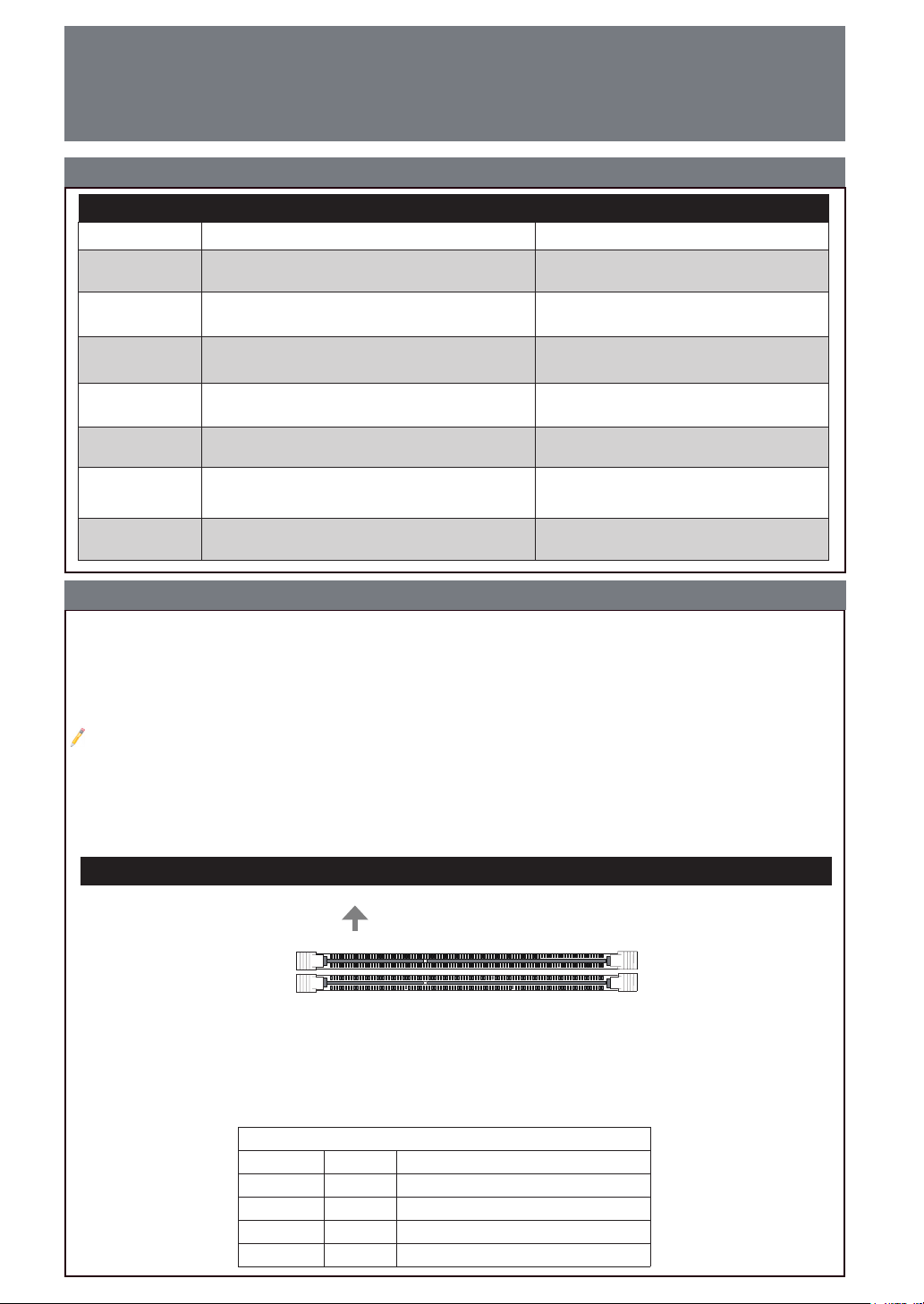
DIMM Memory Installation
Towards the CPU
DIMMA1 (Grey Slot)
DIMMB1 (Grey Slot)
Memory Population Guidelines
When installing memory modules, the DIMM slots should be populated in the following
order: DIMMA1, then DIMMB1.
• Always use DDR4 DIMM modules of the same size, type, and speed.
• Mixed DIMM speeds can be installed. However, all DIMMs will run at the speed of the slowest DIMM.
Recommended Population (Balanced)
DIMMA1 DIMMB1 Total System Memory
4GB 4GB 8GB
8GB 8GB 16GB
16GB 16GB 32GB
32GB 32GB 64GB
Notes
Power Button
Overheat/
Fan Fail LED (-)
1
NIC1 LED (-)
Reset Button
2
HDD LED (-)
POWER LED (-)
Reset
PWR
POWER LED (+)
Ground
Ground
X
X
HDD LED (+)
NIC1 LED (+)
Overheat/
Fan Fail LED (+)
1516
X
X
• Graphics shown in this quick reference guide are for illustration only. Your components may or
may not look exactly the same as drawings shown in this guide.
• Refer to Chapter 2 of the User Manual for detailed information on jumpers, connectors, LED
indicators, memory support and CPU/motherboard installation instructions.
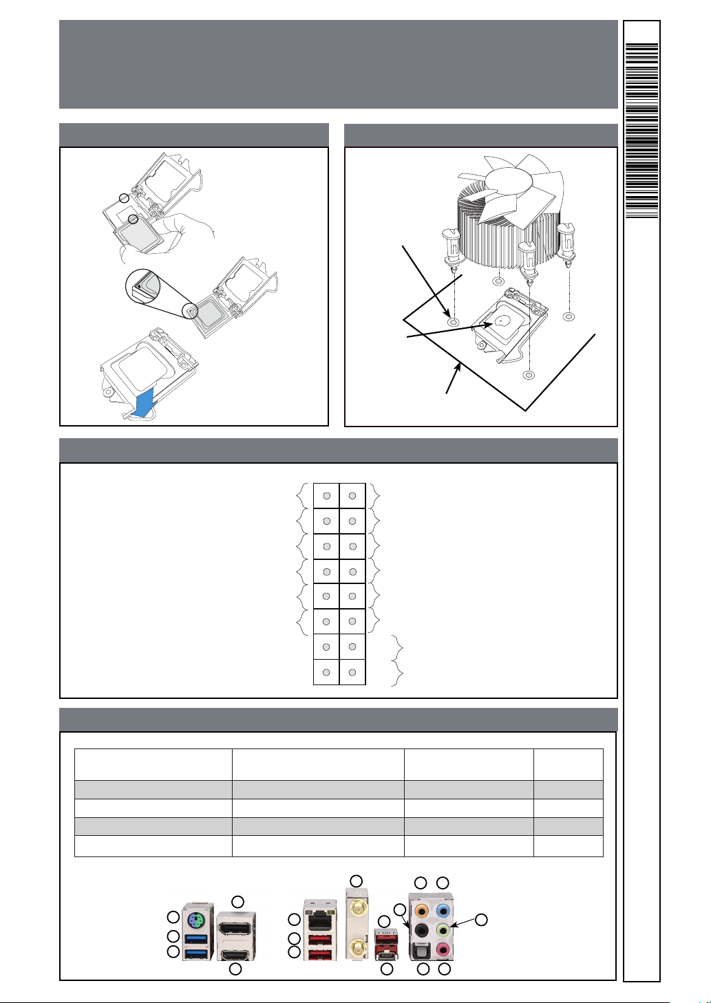
CPU Installation
Front Control Panel (JF1)
Heatsink Installation
Heatsink
with Fan
Mounting Hole
Add
thermal paste
Motherboard
MNL-2018-QRG-10a
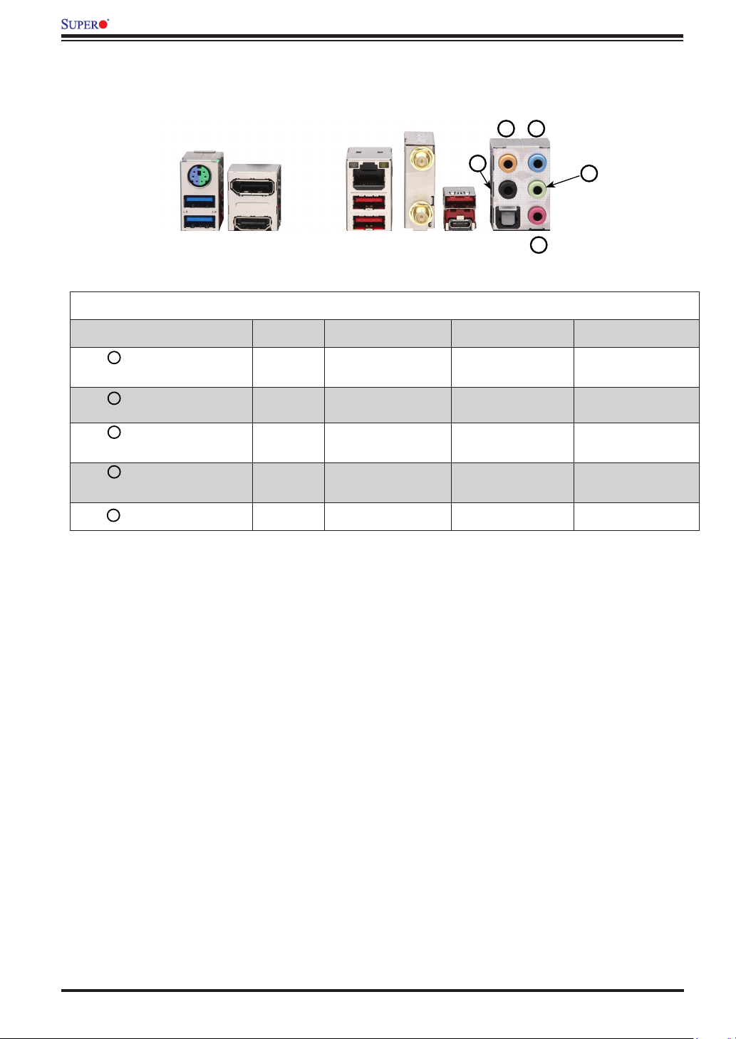
Back Panel I/O Connectors
A. PS/2 Keyboard/Mouse Port F. GbE Ethernet RJ45 LAN Port
B. USB 3.1 Gen1 Port 0 G. USB 3.1 Gen2 Port 4 (Type A) L. Center/LFE Out Q. Mic In
C. USB 3.1 Gen1 Port 1 H. USB 3.1 Gen2 Port 5 (Type A) M. Surround Out
D. DisplayPort 1.2 Port I. WIFI+BT N. S/PDIF Out
E. HDMI 2.0a Port J. USB 3.1 Gen2 Port 6 (Type A) O. Line In
A
B
C
I
D
F
G
H
E
K. USB 3.1 Gen2 Port 7
(Type C)
L
O
M
J
K
N
Q
P. Line Out
P
C9Z390-CG-IW
© 2019 Supermicro Computer Inc. All rights reserved. Reproduction of this document whether in part or in whole is strictly prohibited without
Supermicro's written consent. All Trademarks are property of their respective entities. All information provided is deemed accurate at the time
of printing; however, it is not guaranteed.
 Loading...