

Page 1
SC216 CHASSIS Series
SC216BAC-R920LPB
SC216BE1C-R920LPB SC216BE1C-R920WB
SC216BE2C-R920LPB SC216BE2C-R920WB
SC216BE16-R1K28LPB SC216BE16-R1K28WB
SC216E16-R1200LPB SC216E16-R1200UB
SC216E16-R1010LPB SC216BE16-R920WB
SC216BE16-R920LPB SC216BE16-R920UB
SC216BE-R1K28LPB SC216BE-R1K28WB
SC216E26-R1200LPB SC216E26-R1200UB
SC216BE26-R920LPB SC216BE26-R920WB
SC216BE26-R920UB SC216BA-R1K28WB
SC216BA-R1K28LPB SC216BA-R920WB
SC216BA-R920LPB SC216BA-R920UB
SC216A-R900LPB SC216A-R900UB
SC216E1-R900LPB* SC216E1-R900UB*
SC216E2-R900LPB* SC216E2-R900UB*
USER’S MANUAL
1.0e
Page 2

The information in this User’s Manual has been carefully reviewed and is believed to be accurate.
The vendor assumes no responsibility for any inaccuracies that may be contained in this document,
makes no commitment to update or to keep current the information in this manual, or to notify any
person or organization of the updates. Please Note: For the most up-to-date version of this
manual, please see our web site at www.supermicro.com.
Super Micro Computer, Inc. ("Supermicro") reserves the right to make changes to the product
described in this manual at any time and without notice. This product, including software and
documentation, is the property of Supermicro and/or its licensors, and is supplied only under a
license. Any use or reproduction of this product is not allowed, except as expressly permitted by
the terms of said license.
IN NO EVENT WILL SUPERMICRO BE LIABLE FOR DIRECT, INDIRECT, SPECIAL, INCIDENTAL,
SPECULATIVE OR CONSEQUENTIAL DAMAGES ARISING FROM THE USE OR INABILITY TO
USE THIS PRODUCT OR DOCUMENTATION, EVEN IF ADVISED OF THE POSSIBILITY OF
SUCH DAMAGES. IN PARTICULAR, SUPERMICRO SHALL NOT HAVE LIABILITY FOR ANY
HARDWARE, SOFTWARE, OR DATA STORED OR USED WITH THE PRODUCT, INCLUDING THE
COSTS OF REPAIRING, REPLACING, INTEGRATING, INSTALLING OR RECOVERING SUCH
HARDWARE, SOFTWARE, OR DATA.
Any disputes arising between manufacturer and customer shall be governed by the laws of Santa
Clara County in the State of California, USA. The State of California, County of Santa Clara shall
be the exclusive venue for the resolution of any such disputes. Super Micro's total liability for all
claims will not exceed the price paid for the hardware product.
California Best Management Practices Regulations for Perchlorate Materials: This Perchlorate
warning applies only to products containing CR (Manganese Dioxide) Lithium coin cells. “Perchlorate
Material-special handling may apply. See www.dtsc.ca.gov/hazardouswaste/perchlorate”
WARNING: Handling of lead solder materials used in this
product may expose you to lead, a chemical known to
the State of California to cause birth defects and other
reproductive harm.
Manual Revision 1.0e
Release Date: October 30, 2015
Unless you request and receive written permission from Super Micro Computer, Inc., you may not
copy any part of this document.
Information in this document is subject to change without notice. Other products and companies
referred to herein are trademarks or registered trademarks of their respective companies or mark
holders.
Copyright © 2015 by Super Micro Computer, Inc.
All rights reserved.
Printed in the United States of America
ii
Page 3

Preface
Preface
About This Manual
This manual is written for professional system integrators and PC technicians. It
provides information for the installation and use of the SC216 2U chassis. Installation and maintenance should be performed by experienced technicians only.
This document lists compatible parts and congurations available when this document was published. Always refer to the our Web site for updates on supported
parts and congurations at www.supermicro.com.
Models marked with and asterisk (*) on the front cover have been designated End
of Life, that is, no longer sold.
iii
Page 4

SC216 Chassis Manual
Manual Organization
Chapter 1 Introduction
The rst chapter covers the primary components included with this chassis and
describes the main features of the SC216 chassis. This chapter also includes
contact information.
Chapter 2 Warning Statements for AC Systems
This chapter lists warnings, precautions, and system safety. You should thoroughly
familiarize yourself with this chapter for a general overview of safety precautions
that should be followed before installing and servicing this chassis.
Chapter 3 Chassis Components
Refer here for details on this chassis model including the fans, hard drives, airow
shields, and other components.
Chapter 4 System Interface
Refer to this chapter for details on the system interface, which includes the functions
and information provided by the control panel on the chassis as well as other LEDs
located throughout the system.
Chapter 5 Chassis Setup and Maintenance
This chapter providesdetailed information on this chassis. You should follow the
procedures given in this chapter when installing, removing, or reconguring your
chassis.
Chapter 6 Rack Installation
Refer to this chapter for detailed information on chassis rack installation. You should
follow the procedures given in this chapter when installing, removing or reconguring
your chassis into a rack environment.
Appendices
This section lists compatible cables, power supply specications, and compatible
backplanes. Not all compatible backplanes may be listed. Refer to our Web site for
the latest compatible backplane information at http://www.supermicro.com
iv
Page 5

Preface
Contents
Chapter 1 Introduction
1-1 Overview ......................................................................................................... 1-1
1-2 Contacting Supermicro .................................................................................... 1-3
1-3 Returning Merchandise for Service................................................................. 1-4
Chapter 2 Standardized Warning Statements for AC Systems
2-1 About Standardized Warning Statements ....................................................... 2-1
Warning Denition ........................................................................................... 2-1
Installation Instructions .................................................................................... 2-4
Circuit Breaker ................................................................................................ 2-5
Power Disconnection Warning ........................................................................ 2-6
Equipment Installation ..................................................................................... 2-8
Restricted Area ................................................................................................ 2-9
Battery Handling ............................................................................................ 2-10
Redundant Power Supplies .......................................................................... 2-12
Backplane Voltage ........................................................................................2-13
Comply with Local and National Electrical Codes ........................................ 2-14
Product Disposal ........................................................................................... 2-15
Hot Swap Fan Warning ................................................................................. 2-16
Power Cable and AC Adapter ...................................................................... 2-18
Chapter 3 Chassis Components
3-1 Overview ......................................................................................................... 3-1
3-2 Components .................................................................................................... 3-1
Drives .............................................................................................................. 3-1
Backplane ........................................................................................................ 3-1
Fans ................................................................................................................ 3-1
Mounting Rails ................................................................................................ 3-1
Power Supply .................................................................................................. 3-2
Air Shroud ....................................................................................................... 3-2
3-3 Where to get Replacement Components ........................................................ 3-2
Chapter 4 System Interface
4-1 Overview ......................................................................................................... 4-1
4-2 Control Panel Buttons ..................................................................................... 4-2
4-3 Control Panel LEDs ........................................................................................ 4-2
4-4 Drive Carrier LEDs .......................................................................................... 4-4
SAS/SATA Drives ............................................................................................ 4-4
v
Page 6

SC216 Chassis Manual
Chapter 5 Chassis Setup and Maintenance
5-1 Overview ......................................................................................................... 5-1
5-2 Removing the Power Cord .............................................................................. 5-1
5-3 Removing the Chassis Cover ......................................................................... 5-2
5-4 Installing Hard Drives ...................................................................................... 5-3
Installing the Rear 2.5" Hard Drive - SC216B Only........................................ 5-5
5-5 Installing the Motherboard .............................................................................. 5-7
I/O Shield ........................................................................................................ 5-7
Permanent and Optional Standoffs ................................................................. 5-8
Motherboard Installation .................................................................................. 5-9
5-6 Installing the Expansion Cards ..................................................................... 5-10
Installing Expansion Cards in Low-Prole Model Chassis ........................... 5-10
Installing Riser Cards and Expansion Cards in UIO Models .........................5-11
5-7 Installing the Air Shrouds .............................................................................. 5-13
Installing the Air Shrouds in the Chassis ...................................................... 5-13
Installing the Additional Air Shroud ............................................................... 5-14
5-8 Checking the Airow ..................................................................................... 5-15
5-9 System Fans ................................................................................................. 5-16
5-10 Power Supply ............................................................................................... 5-18
Power Distributor ........................................................................................... 5-20
5-11 Removing the Backplane .............................................................................. 5-21
5-12 Installing the Backplane ................................................................................ 5-23
Chapter 6 Rack Installation
6-1 Overview ......................................................................................................... 6-1
6-2 Unpacking the System .................................................................................... 6-1
6-3 Preparing for Setup ......................................................................................... 6-1
Choosing a Setup Location ............................................................................. 6-1
6-4 Warnings and Precautions .............................................................................. 6-2
Rack Precautions ............................................................................................ 6-2
General Server Precautions ............................................................................ 6-2
Rack Mounting Considerations ....................................................................... 6-3
Ambient Operating Temperature ................................................................ 6-3
Reduced Airow ......................................................................................... 6-3
Mechanical Loading ................................................................................... 6-3
Circuit Overloading ..................................................................................... 6-3
Reliable Ground ......................................................................................... 6-3
vi
Page 7

Preface
6-5 Rack Mounting Instructions ............................................................................. 6-4
Identifying the Sections of the Rack Rails ...................................................... 6-4
Locking Tabs ................................................................................................... 6-5
Releasing the Inner Rail ................................................................................. 6-5
Installing The Inner Rails on the Chassis ....................................................... 6-6
Installing the Outer Rails on the Rack ............................................................ 6-7
Standard Chassis Installation ......................................................................... 6-8
Optional Quick Installation Method ................................................................. 6-9
Appendix A SC216 Chassis Cables
Appendix B SC216 Power Supply Specications
Appendix C SAS-216A Backplane Specications
C-1 ESD Safety Guidelines ...................................................................................C-1
C-2 General Safety Guidelines ..............................................................................C-1
C-3 A Note to Users ...............................................................................................C-2
C-4 Introduction to the SAS-216A Backplane ........................................................C-2
C-5 Front Connector Locations ..............................................................................C-3
Front Connectors ............................................................................................C-3
C-6 Front Connectors and Pin Denitions .............................................................C-4
C-7 Front Jumpers .................................................................................................C-5
Explanation of Jumpers ..................................................................................C-5
I2C and SGPIO Modes and Jumper Settings .................................................C-6
Front LED Indicators .......................................................................................C-7
C-8 Rear Components, Connectors and LED Indicators ......................................C-8
Appendix D SAS-216EL Backplane Specications
D-1 Overview of the SAS-216EL1/EL2 Backplanes ..............................................D-1
D-2 ESD Safety Guidelines ...................................................................................D-2
D-3 General Safety Guidelines ..............................................................................D-2
D-4 An Important Note to Users ............................................................................D-2
D-5 Introduction to the SAS-216EL Backplane......................................................D-3
D-6 Rear Components and Connectors ...............................................................D-4
Rear Components and Connectors ................................................................D-4
D-7 Rear Connectors and Pin Denitions ..............................................................D-5
D-8 Rear Jumper Locations and Pin Denitions ...................................................D-6
Explanation of Jumpers ..................................................................................D-6
D-9 Front Connectors and LED Indicators ............................................................D-8
D-10 Front Connectors and Jumpers ....................................................................D-10
vii
Page 8

SC216 Chassis Manual
Dual Port and Cascading Congurations
D-11 Single and Dual Port Expanders...................................................................D-11
Single Ports ...................................................................................................D-11
Dual Ports .....................................................................................................D-11
D-12 Failover ..........................................................................................................D-12
Single Host Bus Adapter ...............................................................................D-12
Single Host Bus Adapter Failover .................................................................D-12
Dual Host Bus Adapter ................................................................................D-12
Dual Host Bus Adapter Failover....................................................................D-12
D-13 Chassis Power Card and Support Cables ....................................................D-13
Chassis Power Card .....................................................................................D-13
Connectioning an Internal Host Bus Adapter to the Backplane ..................D-14
Supported Internal HBA Cables ....................................................................D-14
Connecting an External Host Bus Adapter to the Backplane ......................D-16
Single External Host Bus Adapter ...............................................................D-16
Dual External Host Bus Adapter ..................................................................D-16
Supported External HBA to Backplane Cable ..............................................D-17
Connecting Multiple Backplanes in a Single Channel Environment .............D-18
Single HBA Conguration Cables .................................................................D-19
Connecting Multiple Backplanes in a Dual Channel Environment ...............D-20
Dual HBA Conguration Cables ....................................................................D-21
D-14 Supported Cascading Congurations ...........................................................D-22
Server System with Single SAS HBA ...........................................................D-23
Dual SAS HBA and Cascaded Conguration ...............................................D-24
Dual SAS HBA and Cascaded Conguration with Branching ......................D-25
Appendix E SAS2-216EL1/EL2 Backplane Specications
Overview of the SAS2-216EL1/EL2 Backplanes ............................................E-1
E-1 ESD Safety Guidelines ...................................................................................E-2
E-2 General Safety Guidelines .............................................................................. E-2
E-3 An Important Note to Users ............................................................................E-2
E-4 Introduction to the SAS2-216EL1/EL2 Backplane ..........................................E-3
E-5 Connectors ...................................................................................................... E-4
E-6 Front Connector and Pin Denitions ............................................................... E-5
E-7 Jumper Locations and Settings.......................................................................E-6
Explanation of Jumpers ..................................................................................E-6
E-8 Front Connectors and LED Indicators ............................................................E-9
viii
Page 9

Preface
Dual Port and Cascading Congurations
E-9 Single and Dual Port Expanders...................................................................E-11
Single Ports ................................................................................................... E-11
Dual Ports .....................................................................................................E-11
E-10 Failover ..........................................................................................................E-12
Single Host Bus Adapter ...............................................................................E-12
Single Host Bus Adapter Failover .................................................................E-12
E-11 Failover with RAID Cards and Multiple HBAs ..............................................E-13
Dual Host Bus Adapter ................................................................................E-13
Dual Host Bus Adapter Failover....................................................................E-13
E-12 Chassis Power Card and Support Cables .................................................... E-14
Chassis Power Card .....................................................................................E-14
Connecting an Internal HBA to the Backplane ............................................E-15
Supported Internal HBA Cables ....................................................................E-15
Connecting an External HBA to the Backplane ...........................................E-17
Single External Host Bus Adapter ...............................................................E-17
Dual External Host Bus Adapter ..................................................................E-17
Supported External HBA to Backplane Cable ..............................................E-18
Connecting Multiple Backplanes in a Single Channel Environment ............. E-19
Single HBA Conguration Cables .................................................................E-20
Connecting Multiple Backplanes in a Dual Channel Environment ...............E-21
Dual HBA Conguration Cables ....................................................................E-22
E-13 Supported Cascading Congurations ...........................................................E-23
Server System with Single SAS HBA ...........................................................E-24
Dual SAS HBA and Cascaded Conguration ...............................................E-25
Dual SAS HBA and Cascaded Conguration with Branching ......................E-26
Appendix F SAS3-216A Backplane Specications
F-1 ESD Safety Guidelines ...................................................................................F-1
F-2 General Safety Guidelines .............................................................................. F-1
Front Connectors ............................................................................................F-2
F-3 A Note to Users ...............................................................................................F-2
F-4 Front Connectors and Jumpers ......................................................................F-2
F-5 Front Connector and Pin Denitions ............................................................... F-3
F-6 Jumpers ...........................................................................................................F-3
Explanation of Jumpers ..................................................................................F-3
F-7 Rear Components, Connectors and LED Indicators ...................................... F-4
Appendix G SAS3-216EL Backplane Specications
ix
Page 10

SC216 Chassis Manual
Notes
x
Page 11
Chapter 1: Introduction
Chapter 1
Introduction
1-1 Overview
Supermicro’s SC216 maximizes storage capacity in a 2U form factor by offering
twenty-four hot-swappable 2.5" SAS/SATA hard drive bays for applications requiring extra storage. The chassis design optimizes every aspect of interior space
without compromising superior cooling capabilities. The chassis is equipped with
a redundant, efcient power supply for outstanding power savings, with specially
designed optimized cooling, and seven low-prole or UIO solution expansion slots
for superior networking options. Quick release, tool-less slide rails are availble for
quick installation.
SC216E1 and SC216E2 chassis models support only SATA, SATA2 and SAS1
hard drives. The maximum capacity supported by each of these drives is 2TB. The
SC216E1 and SC216E2 models do not support JBOD congurations.
Note: A complete list of safety warnings is provided on the Supermicro web site
at www.supermicro.com.
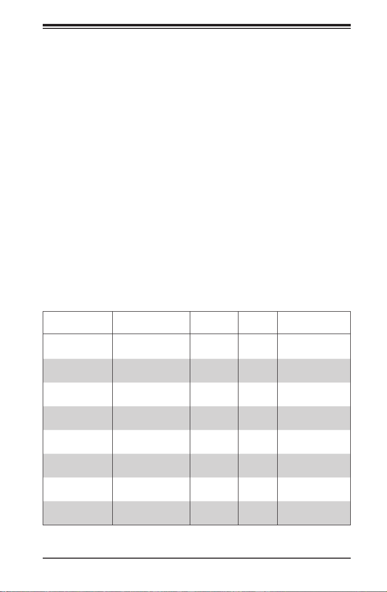
Model HDD Backplane
SC216BAC-
R920LPB
SC216BE1C-
R920LPB
SC216BE1C-
R920WB
SC216BE2C-
R920LPB
SC216BE2C-
R920WB
SC216BE16-
R1K28LPB
SC216BE16-
R1K28WB
SC216E16-
R1200LPB
24x 2.5” SAS/SATA
plus 2x2.5" (opt)
24x 2.5” SAS/SATA
plus 2x2.5" (opt)
24x 2.5” SAS/SATA
plus 2x2.5" (opt)
24x 2.5” SAS/SATA
plus 2x2.5" (opt)
24x 2.5” SAS/SATA
plus 2x2.5" (opt)
24x 2.5” SAS/SATA
plus 2x2.5" (opt)
24x 2.5” SAS/SATA
plus 2x2.5" (opt)
24x 2.5” SAS/SATA
216EL1
216EL1
216EL2
216EL2
216EL1
216EL1
216EL1
1-1
SAS3-
216A
SAS3-
SAS3-
SAS3-
SAS3-
SAS2-
SAS2-
SAS2-
I/O
Slots
7x LP
7x LP
4x FH,
3x LP
7x LP
4x FH,
3x LP
7x LP
4x FH,
3x LP
7x LP
Power
Supply
920W
(Platinum Level)
920W
(Platinum Level)
920W
(Platinum Level)
920W
(Platinum Level)
920W
(Platinum Level)
1280W
(Platinum Level)
1280W
(Platinum Level)
1200W
(Gold Level)
Page 12
SC216 Chassis Manual
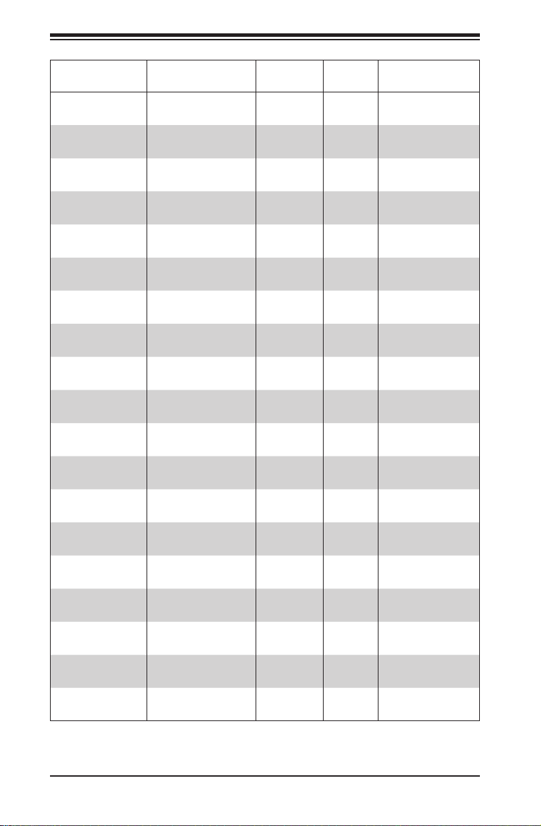
Model HDD Backplane
SC216E16-
R1200UB
SC216E16-
R1010LPB
SC216BE16-
R920LPB
SC216BE16-
R920UB
SC216BE16-
R920WB
SC216BER1K28LPB
SC216BE-
R1K28WB
SC216E26-
R1200LPB
SC216E26-
R1200UB
SC216BE26-
R920LPB
SC216BE26-
R920WB
SC216BE26-
R920UB
SC216BAR1K28LPB
SC216BA-
R1K28WB
SC216BA-
R920LPB
SC216BA-
R920WB
SC216BA-
R920UB
SC216AR900LPB
SC216A-
R900UB
24x 2.5” SAS/SATA
24x 2.5” SAS/SATA
24x 2.5” SAS/SATA
plus 2x2.5" (opt)
24x 2.5” SAS/SATA
plus 2x2.5" (opt)
24x 2.5” SAS/SATA
plus 2x2.5" (opt)
24x 2.5” SAS/SATA
plus 2x2.5" (opt)
24x 2.5” SAS/SATA
plus 2x2.5" (opt)
24x 2.5” SAS/SATA
24x 2.5” SAS/SATA
24x 2.5” SAS/SATA
plus 2x2.5" (opt)
24x 2.5” SAS/SATA
plus 2x2.5" (opt)
24x 2.5” SAS/SATA
plus 2x2.5" (opt)
24x 2.5” SAS/SATA
plus 2x2.5" (opt)*
24x 2.5” SAS/SATA
plus 2x2.5" (opt)
24x 2.5” SAS/SATA
plus 2x2.5" (opt)
24x 2.5” SAS/SATA
plus 2x2.5" (opt)
24x 2.5” SAS/SATA
plus 2x2.5" (opt)
24x 2.5” SAS/SATA SAS-216A 7x LP 900W
24x 2.5” SAS/SATA SAS-216A
SAS2-
216EL1
SAS2-
216EL1
SAS2-
216EL1
SAS2-
216EL1
SAS2-
216EL1
SAS2-
216EL2
SAS2-
216EL2
SAS2-
216EL2
SAS2-
216EL2
SAS2-
216EL2
SAS2-
216EL2
SAS2-
216EL2
SAS-216A 7x LP
SAS-216A
SAS-216A 7x LP
SAS-216A 7x LP
SAS-216A
I/O
Slots
4x FH,
3x LP
7x LP 1010W DC
7x LP
4x FH,
3x LP
4x FH,
3x LP
7x LP
4x FH,
3x LP
7x LP
4x FH,
3x LP
7x LP
4x FH,
3x LP
4x FH,
3x LP
4x FH,
3x LP
4x FH,
3x LP
4x FH,
3x LP
Power
Supply
1200W
(Gold Level)
920W
(Platinum Level)
920W
(Platinum Level)
920W
(Platinum Level)
1280W
(Platinum Level)
1280W
(Platinum Level)
1200W
(Gold Level)
1200W
(Gold Level)t
920W
(Platinum Level)
920W
(Platinum Level)
920W
(Platinum Level)
1280W
(Platinum Level)
1280W
(Platinum Level)
920W
(Platinum Level)
920W
(Platinum Level)
920W
(Platinum Level)
900W
1-2
Page 13
Chapter 1: Introduction
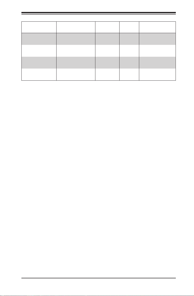
Model HDD Backplane
SC216E1-
R900LPB**
SC216E1-
R900UB**
SC216E2-
R900LPB**
SC216E2-
R900UB**
*Optional with SC216B models: two additional 2.5" drives that mount in the rear
of the chassis.
** End of Life
Key: FH = Full-height, half-length, LP = Low-prole
24x 2.5” SAS/SATA
24x 2.5” SAS/SATA
24x 2.5” SAS/SATA
24x 2.5” SAS/SATA
SAS-
216EL1
SAS-
216EL1
SAS-
216EL2
SAS-
216EL2
I/O
Slots
7x LP 900W
4x FH,
3x LP
7x LP 900W
4x FH,
3x LP
Power
Supply
900W
900W
1-3
Page 14

SC216 Chassis Manual
1-2 Contacting Supermicro
Headquarters
Address: Super Micro Computer, Inc.
980 Rock Ave.
San Jose, CA 95131 U.S.A.
Tel: +1 (408) 503-8000
Fax: +1 (408) 503-8008
Email: marketing@supermicro.com (General Information)
support@supermicro.com (Technical Support)
Web Site: www.supermicro.com
Europe
Address: Super Micro Computer B.V.
Het Sterrenbeeld 28, 5215 ML
's-Hertogenbosch, The Netherlands
Tel: +31 (0) 73-6400390
Fax: +31 (0) 73-6416525
Email: sales@supermicro.nl (General Information)
support@supermicro.nl (Technical Support)
rma@supermicro.nl (Customer Support)
Web Site: www.supermicro.nl
Asia-Pacic
Address: Super Micro Computer, Inc.
3F, No. 150, Jian 1st Rd.
Zhonghe Dist., New Taipei City 235
Taiwan (R.O.C)
Tel: +886-(2) 8226-3990
Fax: +886-(2) 8226-3992
Email: support@supermicro.com.tw
Web Site: www.supermicro.com.tw
1-4
Page 15

Chapter 1: Introduction
1-3 Returning Merchandise for Service
A receipt or copy of your invoice marked with the date of purchase is required before any warranty service will be rendered. You can obtain service by calling your
vendor for a Returned Merchandise Authorization (RMA) number. When returning to
the manufacturer, the RMA number should be prominently displayed on the outside
of the shipping carton, and mailed prepaid or hand-carried. Shipping and handling
charges will be applied for all orders that must be mailed when service is complete.
For faster service, RMA authorizations may be requested online (http://www.supermicro.com/support/rma/).
Whenever possible, repack the chassis in the original Supermicro carton, using the
original packaging material. If these are no longer available, be sure to pack the
chassis securely, using packaging material to surround the chassis so that it does
not shift within the carton and become damaged during shipping.
This warranty only covers normal consumer use and does not cover damages incurred in shipping or from failure due to the alteration, misuse, abuse or improper
maintenance of products.
During the warranty period, contact your distributor rst for any product problems.
1-5
Page 16

SC216 Chassis Manual
Notes
1-6
Page 17
Chapter 2: Warning Statements for AC Systems
Chapter 2
Standardized Warning Statements for AC Systems
2-1 About Standardized Warning Statements
The following statements are industry standard warnings, provided to warn the user
of situations which have the potential for bodily injury. Should you have questions
or experience difficulty, contact Supermicro's Technical Support department
for assistance. Only certied technicians should attempt to install or congure
components.
Read this appendix in its entirety before installing or conguring components in the
Supermicro chassis.
These warnings may also be found on our web site at http://www.supermicro.com/
about/policies/safety_information.cfm.
Warning Denition
Warning!
This warning symbol means danger. You are in a situation that could cause bodily
injury. Before you work on any equipment, be aware of the hazards involved with
electrical circuitry and be familiar with standard practices for preventing accidents.
警告の定義
この警告サイン は 危 険 を意 味します。
人身事故につながる可能性がありますので、いずれの機器でも動作させる前に、
電気回路に含まれる危険性に注意して、標準的な事故防止策に精通して下さい。
此警告符号代表危险。
您正处于可能受到严重伤害的工作环境中。在您使用设备开始工作之前,必须充分
意识到触电的危险,并熟练掌握防止事故发生的标准工作程序。请根据每项警告结
尾的声明号码找到此设备的安全性警告说明的翻译文本。
此警告符號代表危險。
您正處於可能身體可能會受損傷的工作環境中。在您使用任何設備之前,請注意觸
電的危險,並且要熟悉預防事故發生的標準工作程序。請依照每一注意事項後的號
碼找到相關的翻譯說明內容。
2-1
Page 18

SC216 Chassis Manual
Warnung
WICHTIGE SICHERHEITSHINWEISE
Dieses Warnsymbol bedeutet Gefahr. Sie benden sich in einer Situation, die zu
Verletzungen führen kann. Machen Sie sich vor der Arbeit mit Geräten mit den
Gefahren elektrischer Schaltungen und den üblichen Verfahren zur Vorbeugung
vor Unfällen vertraut. Suchen Sie mit der am Ende jeder Warnung angegebenen
Anweisungsnummer nach der jeweiligen Übersetzung in den übersetzten
Sicherheitshinweisen, die zusammen mit diesem Gerät ausgeliefert wurden.
BEWAHREN SIE DIESE HINWEISE GUT AUF.
INSTRUCCIONES IMPORTANTES DE SEGURIDAD
Este símbolo de aviso indica peligro. Existe riesgo para su integridad física. Antes
de manipular cualquier equipo, considere los riesgos de la corriente eléctrica y
familiarícese con los procedimientos estándar de prevención de accidentes. Al
nal de cada advertencia encontrará el número que le ayudará a encontrar el texto
traducido en el apartado de traducciones que acompaña a este dispositivo.
GUARDE ESTAS INSTRUCCIONES.
IMPORTANTES INFORMATIONS DE SÉCURITÉ
Ce symbole d'avertissement indique un danger. Vous vous trouvez dans une
situation pouvant entraîner des blessures ou des dommages corporels. Avant
de travailler sur un équipement, soyez conscient des dangers liés aux circuits
électriques et familiarisez-vous avec les procédures couramment utilisées pour
éviter les accidents. Pour prendre connaissance des traductions des avertissements
gurant dans les consignes de sécurité traduites qui accompagnent cet appareil,
référez-vous au numéro de l'instruction situé à la n de chaque avertissement.
CONSERVEZ CES INFORMATIONS.
ןונקת תורהצהאהרהז
ןה תואבה תורהצהא ינפמ שמתשמה תא ריהזהל תנמ לע ,היישעתה ינקת יפ לע תורהז הלבח
ה וא תולאש שיו הדימב .תירשפא תיזיפי ,יהשלכ היעבב תולקתרוציל שי הכימת תקלחמ םע רשק
רידגהל וא ןיקתהל םיאשר דבלב םיכמסומ םיאנכט .ורקימרפוס לש תינכט תאה .םיביכר
אורקל שי .ורקימרפוס יזראמב םיביכרה תרדגה וא תנקתה ינפל ואולמב חפסנה תא
2-2
Page 19

Chapter 2: Warning Statements for AC Systems
. !
안전을 위한 주의사항
경고!
이 경고 기호는 위험이 있음을 알려 줍니다. 작업자의 신체에 부상을 야기 할 수
있는 상태에 있게 됩니다. 모든 장비에 대한 작업을 수행하기 전에 전기회로와
관련된 위험요소들을 확인하시고 사전에 사고를 방지할 수 있도록 표준
작업절차를 준수해 주시기 바랍니다.
해당 번역문을 찾기 위해 각 경고의 마지막 부분에 제공된 경고문 번호를
참조하십시오
BELANGRIJKE VEILIGHEIDSINSTRUCTIES
Dit waarschuwings symbool betekent gevaar. U verkeert in een situatie die
lichamelijk letsel kan veroorzaken. Voordat u aan enige apparatuur gaat werken,
dient u zich bewust te zijn van de bij een elektrische installatie betrokken risico's
en dient u op de hoogte te zijn van de standaard procedures om ongelukken te
voorkomen. Gebruik de nummers aan het eind van elke waarschuwing om deze te
herleiden naar de desbetreffende locatie.
BEWAAR DEZE INSTRUCTIES
2-3
2-3
Page 20

SC216 Chassis Manual
Installation Instructions
Warning!
Read the installation instructions before connecting the system to the power source.
設置手順書
システムを電源に接続する前に、設置手順書をお読み下さい。
警告
将此系统连接电源前,请先阅读安装说明。
警告
將系統與電源連接前,請先閱讀安裝說明。
Warnung
Vor dem Anschließen des Systems an die Stromquelle die Installationsanweisungen
lesen.
¡Advertencia!
Lea las instrucciones de instalación antes de conectar el sistema a la red de
alimentación.
Attention
Avant de brancher le système sur la source d'alimentation, consulter les directives
d'installation.
אורקל שי רוקמל תכרעמה רוביח ינפל הנקתה תוארוה תאחתמ.
시스템을 전원에 연결하기 전에 설치 안내를 읽어주십시오.
Waarschuwing
Raadpleeg de installatie-instructies voordat u het systeem op de voedingsbron
aansluit.
2-4
Page 21

Chapter 2: Warning Statements for AC Systems
Circuit Breaker
Warning!
This product relies on the building's installation for short-circuit (overcurrent)
protection. Ensure that the protective device is rated not greater than: 250 V, 20 A.
サーキット・ブレーカー
この製品は、短絡(過電流)保護装置がある建物での設置を前提としています。
保護装置の定格が250 V、20 Aを超えないことを確認下さい。
警告
此产品的短路(过载电流)保护由建筑物的供电系统提供,确保短路保护设备的额定电
流不大于250V,20A。
警告
此產品的短路(過載電流)保護由建築物的供電系統提供,確保短路保護設備的額定電
流不大於250V,20A。
Warnung
Dieses Produkt ist darauf angewiesen, dass im Gebäude ein Kurzschlussbzw. Überstromschutz installiert ist. Stellen Sie sicher, dass der Nennwert der
Schutzvorrichtung nicht mehr als: 250 V, 20 A beträgt.
¡Advertencia!
Este equipo utiliza el sistema de protección contra cortocircuitos (o sobrecorrientes)
del edicio. Asegúrese de que el dispositivo de protección no sea superior a: 250
V, 20 A.
Attention
Pour ce qui est de la protection contre les courts-circuits (surtension), ce produit
dépend de l'installation électrique du local. Vériez que le courant nominal du
dispositif de protection n'est pas supérieur à :250 V, 20 A.
לע ךמתסמ הז רצומנגהה תעינמל םינבמב תנקתומה יכ אדוול שי .ילמשח רצק
רצקה ינפמ ןגמה רישכמה ילמשחהמ רתוי אל אוה-250 V, 20 A
20A, 250V :
2-5
Page 22
SC216 Chassis Manual
경고!
이 제품은 전원의 단락(과전류)방지에 대해서 전적으로 건물의 관련 설비에
의존합니다. 보호장치의 정격이 반드시 250V(볼트), 20A(암페어)를 초과하지
않도록 해야 합니다.
Waarschuwing
Dit product is afhankelijk van de kortsluitbeveiliging (overspanning) van
uw electrische installatie. Controleer of het beveiligde aparaat niet groter
gedimensioneerd is dan 220V, 20A.
Power Disconnection Warning
Warning!
The system must be disconnected from all sources of power and the power cord
removed from the power supply module(s) before accessing the chassis interior to
install or remove system components.
電源切断の警告
システムコンポーネントの取り付けまたは 取り外しのために、シャーシー内部にアクセス
するには、
システムの電源はすべてのソースから切断され、電源コードは電源モジュールから取り
外す必要があります。
警告
在你打开机箱并安装或移除内部器件前,必须将系统完全断电,并移除电源线。
警告
在您打開機殼安裝或移除內部元件前,必須將系統完全斷電,並移除電源線。
Warnung
Das System muss von allen Quellen der Energie und vom Netzanschlusskabel
getrennt sein, das von den Spg.Versorgungsteilmodulen entfernt wird, bevor es
auf den Chassisinnenraum zurückgreift, um Systemsbestandteile anzubringen oder
zu entfernen.
2-6
Page 23

Chapter 2: Warning Statements for AC Systems
ילמשח קותינ ינפמ הרהזא
¡Advertencia!
El sistema debe ser disconnected de todas las fuentes de energía y del cable
eléctrico quitado de los módulos de fuente de alimentación antes de tener acceso
el interior del chasis para instalar o para quitar componentes de sistema.
Attention
Le système doit être débranché de toutes les sources de puissance ainsi que de
son cordon d'alimentation secteur avant d'accéder à l'intérieur du chassis pour
installer ou enlever des composants de systéme.
!הרהזא
למשחה תורוקמ לכמ תכרעמה תא קתנל שי ריסהל שיו קפסהמ ילמשחה לבכ תא
נקתה ךרוצל זראמה לש ימינפה קלחל השיג ינפלת רסה ואת .םיביכר
경고!
시스템에 부품들을 장착하거나 제거하기 위해서는 섀시 내부에 접근하기 전에
반드시 전원 공급장치로부터 연결되어있는 모든 전원과 전기코드를 분리해주어야
합니다.
Waarschuwing
Voordat u toegang neemt tot het binnenwerk van de behuizing voor het installeren
of verwijderen van systeem onderdelen, dient u alle spanningsbronnen en alle
stroomkabels aangesloten op de voeding(en) van de behuizing te verwijderen
2-7
Page 24

SC216 Chassis Manual
Equipment Installation
Warning!
Only trained and qualied personnel should be allowed to install, replace, or service
this equipment.
機器の設置
トレーニングを受け認定された人だけがこの装置の設置、交換、またはサービスを許可
されています。
警告
只有经过培训且具有资格的人员才能进行此设备的安装、更换和维修。
警告
只有經過受訓且具資格人員才可安裝、更換與維修此設備。
Warnung
Das Installieren, Ersetzen oder Bedienen dieser Ausrüstung sollte nur geschultem,
qualiziertem Personal gestattet werden.
¡Advertencia!
Solamente el personal calicado debe instalar, reemplazar o utilizar este equipo.
Attention
Il est vivement recommandé de confier l'installation, le remplacement et la
maintenance de ces équipements à des personnels qualiés et expérimentés.
!הרהזא
שר דבלב ךמסומ תווצתא ףילחהל ,ןיקתהל יא .דויצה רובע תוריש תתל וא דויצה
경고!
훈련을 받고 공인된 기술자만이 이 장비의 설치, 교체 또는 서비스를 수행할 수
있습니다.
2-8
Page 25

Chapter 2: Warning Statements for AC Systems
Waarschuwing
Deze apparatuur mag alleen worden geïnstalleerd, vervangen of hersteld door
geschoold en gekwaliceerd personeel.
Restricted Area
Warning!
This unit is intended for installation in restricted access areas. A restricted access
area can be accessed only through the use of a special tool, lock and key, or other
means of security. (This warning does not apply to workstations).
アクセス制限区域
このユニットは、アクセス制限区域に設置されることを想定しています。
アクセス制限区域は、特別なツール、鍵と錠前、その他のセキュリティの手段を用いての
み出入りが可能です。
警告
此部件应安装在限制进出的场所,限制进出的场所指只能通过使用特殊工具、锁和
钥匙或其它安全手段进出的场所。
警告
此裝置僅限安裝於進出管制區域,進出管制區域係指僅能以特殊工具、鎖頭及鑰匙
或其他安全方式才能進入的區域。
Warnung
Diese Einheit ist zur Installation in Bereichen mit beschränktem Zutritt vorgesehen.
Der Zutritt zu derartigen Bereichen ist nur mit einem Spezialwerkzeug, Schloss und
Schlüssel oder einer sonstigen Sicherheitsvorkehrung möglich.
¡Advertencia!
Esta unidad ha sido diseñada para instalación en áreas de acceso restringido.
Sólo puede obtenerse acceso a una de estas áreas mediante la utilización de una
herramienta especial, cerradura con llave u otro medio de seguridad.
Attention
Cet appareil doit être installée dans des zones d'accès réservés. L'accès à une
zone d'accès réservé n'est possible qu'en utilisant un outil spécial, un mécanisme
de verrouillage et une clé, ou tout autre moyen de sécurité.
2-9
Page 26
SC216 Chassis Manual
תלבגומ השיג םע רוזא
!הרהזא
תרזעב תנתינ השיגה .השיג תלבגה םהב שיש םירוזאב הדיחיה תא ןיקתהל שי
.)'דכו לוענמ ,חתפמ( דבלב החטבא ילכ
.
경고!
이 장치는 접근이 제한된 구역에 설치하도록 되어있습니다. 특수도구, 잠금 장치 및
키, 또는 기타 보안 수단을 통해서만 접근 제한 구역에 들어갈 수 있습니다.
Waarschuwing
Dit apparaat is bedoeld voor installatie in gebieden met een beperkte toegang.
Toegang tot dergelijke gebieden kunnen alleen verkregen worden door gebruik te
maken van speciaal gereedschap, slot en sleutel of andere veiligheidsmaatregelen.
Battery Handling
Warning!
There is the danger of explosion if the battery is replaced incorrectly. Replace the
battery only with the same or equivalent type recommended by the manufacturer.
Dispose of used batteries according to the manufacturer's instructions
電池の取り扱い
電池交換が正しく行われなかった場合、破裂の危険性があります。 交換する電池はメー
カーが推奨する型、または同等のものを使用下さい。 使用済電池は製造元の指示に従
って処分して下さい。
警告
电池更换不当会有爆炸危险。请只使用同类电池或制造商推荐的功能相当的电池更
换原有电池。请按制造商的说明处理废旧电池。
警告
電池更換不當會有爆炸危險。請使用製造商建議之相同或功能相當的電池更換原有
電池。請按照製造商的說明指示處理廢棄舊電池。
2-10
Page 27

Chapter 2: Warning Statements for AC Systems
Warnung
Bei Einsetzen einer falschen Batterie besteht Explosionsgefahr. Ersetzen Sie die
Batterie nur durch den gleichen oder vom Hersteller empfohlenen Batterietyp.
Entsorgen Sie die benutzten Batterien nach den Anweisungen des Herstellers.
Attention
Danger d'explosion si la pile n'est pas remplacée correctement. Ne la remplacer
que par une pile de type semblable ou équivalent, recommandée par le fabricant.
Jeter les piles usagées conformément aux instructions du fabricant.
¡Advertencia!
Existe peligro de explosión si la batería se reemplaza de manera incorrecta.
Reemplazar la batería exclusivamente con el mismo tipo o el equivalente
recomendado por el fabricante. Desechar las baterías gastadas según las
instrucciones del fabricante.
!הרהזא
תנכס תמייקץוציפ .הניקת אל ךרדב הפלחוהו הדימב הללוסה לש ףילחהל שי
גוסב הללוסה תא מ םאותה תרבחלמומ ןרציתצ.
תוללוסה קוליס תושמושמה עצבל שי .ןרציה תוארוה יפל
경고!
배터리가 올바르게 교체되지 않으면 폭발의 위험이 있습니다. 기존 배터리와
동일하거나 제조사에서 권장하는 동등한 종류의 배터리로만 교체해야 합니다.
제조사의 안내에 따라 사용된 배터리를 처리하여 주십시오.
Waarschuwing
Er is ontplofngsgevaar indien de batterij verkeerd vervangen wordt. Vervang de
batterij slechts met hetzelfde of een equivalent type die door de fabrikant aanbevolen
wordt. Gebruikte batterijen dienen overeenkomstig fabrieksvoorschriften afgevoerd
te worden.
2-11
Page 28

SC216 Chassis Manual
Redundant Power Supplies
Warning!
This unit might have more than one power supply connection. All connections must
be removed to de-energize the unit.
冗長電源装置
このユニットは複数の電源装置が接続されている場合があります。
ユニットの電源を切るためには、すべての接続を取り外さなければなりません。
警告
此部件连接的电源可能不止一个,必须将所有电源断开才能停止给该部件供电。
警告
此裝置連接的電源可能不只一個,必須切斷所有電源才能停止對該裝置的供電。
Warnung
Dieses Gerät kann mehr als eine Stromzufuhr haben. Um sicherzustellen, dass
der Einheit kein trom zugeführt wird, müssen alle Verbindungen entfernt werden.
¡Advertencia!
Puede que esta unidad tenga más de una conexión para fuentes de alimentación.
Para cortar por completo el suministro de energía, deben desconectarse todas las
conexiones.
Attention
Cette unité peut avoir plus d'une connexion d'alimentation. Pour supprimer toute
tension et tout courant électrique de l'unité, toutes les connexions d'alimentation
doivent être débranchées.
דחא קפסמ רתוי םייק םא
!הרהזא
.קפס לש דחא רוביחמ רתוי שי הדחיל תא ריסהל שי
חיה תאי.הד
2-12
Page 29
Chapter 2: Warning Statements for AC Systems
.
경고!
이 장치에는 한 개 이상의 전원 공급 단자가 연결되어 있을 수 있습니다. 이 장치에
전원을 차단하기 위해서는 모든 연결 단자를 제거해야만 합니다.
Waarschuwing
Deze eenheid kan meer dan één stroomtoevoeraansluiting bevatten. Alle
aansluitingen dienen verwijderd te worden om het apparaat stroomloos te maken.
Backplane Voltage
Warning!
Hazardous voltage or energy is present on the backplane when the system is
operating. Use caution when servicing.
バックプレーンの電 圧
システムの稼働中は危険な電圧または電力が、バックプレーン上にかかっています。
修理する際には注意ください。
警告
当系统正在进行时,背板上有很危险的电压或能量,进行维修时务必小心。
警告
當系統正在進行時,背板上有危險的電壓或能量,進行維修時務必小心。
Warnung
Wenn das System in Betrieb ist, treten auf der Rückwandplatine gefährliche
Spannungen oder Energien auf. Vorsicht bei der Wartung.
¡Advertencia!
Cuando el sistema está en funcionamiento, el voltaje del plano trasero es peligroso.
Tenga cuidado cuando lo revise.
Attention
Lorsque le système est en fonctionnement, des tensions électriques circulent sur
le fond de panier. Prendre des précautions lors de la maintenance.
2-13
Page 30
SC216 Chassis Manual
ירוחאה לנפב חתמ
ךלהמב רהזיהל שי .תכרעמה לועפת ןמזב ירוחאה לנפב חתמ תנכס תמייק
.הדובעה
경고!
시스템이 동작 중일 때 후면판 (Backplane)에는 위험한 전압이나 에너지가 발생
합니다. 서비스 작업 시 주의하십시오.
Waarschuwing
Een gevaarlijke spanning of energie is aanwezig op de backplane wanneer het
systeem in gebruik is. Voorzichtigheid is geboden tijdens het onderhoud.
Comply with Local and National Electrical Codes
זא!הרה
Warning!
Installation of the equipment must comply with local and national electrical codes.
地方および国の電気規格に準拠
機器の取り付けはその地方および国の電気規格に準拠する必要があります。
警告
设备安装必须符合本地与本国电气法规。
警告
設備安裝必須符合本地與本國電氣法規。
Warnung
Die Installation der Geräte muss den Sicherheitsstandards entsprechen.
¡Advertencia!
La instalacion del equipo debe cumplir con las normas de electricidad locales y
nacionales.
2-14
Page 31

Chapter 2: Warning Statements for AC Systems
Attention
L'équipement doit être installé conformément aux normes électriques nationales
et locales.
יצראה למשחה יקוח םואית
!הרהזא
תנקתה םייצראהו םיימוקמה למשחה יקוחל תמאות תויהל תבייח דויצה.
경고!
현 지역 및 국가의 전기 규정에 따라 장비를 설치해야 합니다.
Waarschuwing
Bij installatie van de apparatuur moet worden voldaan aan de lokale en nationale
elektriciteitsvoorschriften.
Product Disposal
Warning!
Ultimate disposal of this product should be handled according to all national laws
and regulations.
製品の廃棄
この製品を廃棄処分する場合、国の関係する全ての法律・条例に従い処理する必要が
あります。
警告
本产品的废弃处理应根据所有国家的法律和规章进行。
警告
本產品的廢棄處理應根據所有國家的法律和規章進行。
Warnung
Die Entsorgung dieses Produkts sollte gemäß allen Bestimmungen und Gesetzen
des Landes erfolgen.
2-15
Page 32

SC216 Chassis Manual
¡Advertencia!
Al deshacerse por completo de este producto debe seguir todas las leyes y
reglamentos nacionales.
Attention
La mise au rebut ou le recyclage de ce produit sont généralement soumis à des
lois et/ou directives de respect de l'environnement. Renseignez-vous auprès de
l'organisme compétent.
רצומה קוליס
!הרהזא
ו תויחנהל םאתהב תויהל בייח הז רצומ לש יפוס קוליס.הנידמה יקוח
경고!
이 제품은 해당 국가의 관련 법규 및 규정에 따라 폐기되어야 합니다.
Waarschuwing
De uiteindelijke verwijdering van dit product dient te geschieden in overeenstemming
met alle nationale wetten en reglementen.
Hot Swap Fan Warning
Warning!
The fans might still be turning when you remove the fan assembly from the chassis.
Keep ngers, screwdrivers, and other objects away from the openings in the fan
assembly's housing.
ファン・ホット ス ワッ プ の 警 告
シャーシから冷却ファン装置を取り外した際、ファンがまだ回転している可能性がありま
す。 ファンの開口部に、指、ドライバー、およびその他のものを近づけないで下さい。
警告
当您从机架移除风扇装置,风扇可能仍在转动。小心不要将手指、螺丝起子和其他
物品太靠近风扇
2-16
Page 33

Chapter 2: Warning Statements for AC Systems
警告
當您從機架移除風扇裝置,風扇可能仍在轉動。小心不要將手指、螺絲起子和其他
物品太靠近風扇。
Warnung
Die Lüfter drehen sich u. U. noch, wenn die Lüfterbaugruppe aus dem Chassis
genommen wird. Halten Sie Finger, Schraubendreher und andere Gegenstände
von den Öffnungen des Lüftergehäuses entfernt.
¡Advertencia!
Los ventiladores podran dar vuelta cuando usted quite ell montaje del ventilador
del chasis. Mandtenga los dedos, los destornilladores y todos los objetos lejos de
las aberturas del ventilador
Attention
Il est possible que les ventilateurs soient toujours en rotation lorsque vous retirerez
le bloc ventilateur du châssis. Prenez garde à ce que doigts, tournevis et autres
objets soient éloignés du logement du bloc ventilateur.
!הרהזא
יקלח תא םיריסמ רשאכ שי .םידבוע ןיידע םיררוואמהו ןכתי ,זראמהמ ררוואמה
קיחרהללררוואמה ךותב םיחתפהמ םינוש הדובע ילכו תועבצאה תא חוטב קחרמ
.
경고!
섀시로부터 팬 조립품을 제거할 때 팬은 여전히 회전하고 있을 수 있습니다. 팬
조림품 외관의 열려있는 부분들로부터 손가락 및 스크류드라이버, 다른 물체들이
가까이 하지 않도록 배치해 주십시오.
Waarschuwing
Het is mogelijk dat de ventilator nog draait tijdens het verwijderen van het
ventilatorsamenstel uit het chassis. Houd uw vingers, schroevendraaiers
en eventuele andere voorwerpen uit de buurt van de openingen in de
ventilatorbehuizing.
2-17
Page 34

SC216 Chassis Manual
Power Cable and AC Adapter
Warning!
When installing the product, use the provided or designated connection cables,
power cables and AC adaptors. Using any other cables and adaptors could cause
a malfunction or a re. Electrical Appliance and Material Safety Law prohibits the
use of UL or CSA -certied cables (that have UL/CSA shown on the code) for any
other electrical devices than products designated by Supermicro only.
電源コードとACアダプター
製品を設置する場合、提供または指定された接続ケーブル、電源コードとACアダプター
を使用下さい。 他のケーブルやアダプタを使用すると故障や火災の原因になることがあ
ります。 電気用品安全法は、ULまたはCSA認定のケーブル(UL/CSEマークがコードに表
記)を Supermicroが指定する製品以外に使用することを禁止しています。
警告
安装此产品时,请使用本身提供的或指定的连接线,电源线和电源适配器.使用其它线
材或适配器可能会引起故障或火灾。除了Supermicro所指定的产品,电气用品和材
料安全法律规定禁止使用未经UL或CSA认证的线材。(线材上会显示UL/CSA符号)。
警告
安裝此產品時,請使用本身提供的或指定的連接線,電源線和電源適配器.使用其它線
材或適配器可能會引起故障或火災。除了Supermicro所指定的產品,電氣用品和材
料安全法律規定禁止使用未經UL或CSA認證的線材。(線材上會顯示UL/CSA符號)。
Warnung
Bei der Installation des Produkts, die zur Verfügung gestellten oder benannt
Anschlusskabel, Stromkabel und Netzteile. Verwendung anderer Kabel und Adapter
kann zu einer Fehlfunktion oder ein Brand entstehen. Elektrische Geräte und
Material Safety Law verbietet die Verwendung von UL-oder CSA-zertizierte Kabel,
UL oder CSA auf der Code für alle anderen elektrischen Geräte als Produkte von
Supermicro nur bezeichnet gezeigt haben.
¡Advertencia!
Al instalar el producto, utilice los cables de conexión previstos o designados, los
cables y adaptadores de CA. La utilización de otros cables y adaptadores podría
ocasionar un mal funcionamiento o un incendio. Aparatos Eléctricos y la Ley de
Seguridad del Material prohíbe el uso de UL o CSA cables certicados que tienen
UL o CSA se muestra en el código de otros dispositivos eléctricos que los productos
designados por Supermicro solamente.
2-18
Page 35

Chapter 2: Warning Statements for AC Systems
UL
Attention
Lors de l'installation du produit, utilisez les bables de connection fournis ou désigné.
L'utilisation d'autres cables et adaptateurs peut provoquer un dysfonctionnement
ou un incendie. Appareils électroménagers et de loi sur la sécurité Matériel interdit
l'utilisation de UL ou CSA câbles certiés qui ont UL ou CSA indiqué sur le code
pour tous les autres appareils électriques que les produits désignés par Supermicro
seulement.
אתמו םיילמשחמ יAC
!הרהזא
םימאתמו םיקפס ,םילבכב שמתשהל שי ,רצומה תא םיניקתמ רשאכAC רשא
וא הלקתל םורגל לוכי רחא םאתמ וא לבכ לכב שומיש .ךכ םשל וקפוסו ודעונ
טב יקוחו למשח ירישכמב שומיש יקוח יפ לע .ילמשח רצק רוסיא םייק ,תוחי
UL ב וא- CSA לש דוק םהילע עיפומ ראשכ(
ב םיכמסומה םילבכב שמתשהל-
UL/CSA) רחא ילמשח רצומ לכ רובע.דבלב ורקימקרפוס ידי לע ןיוצ אלש
. .
CSA
Supermicro
(UL/CSA )
경고!
제품을 설치할 때에는 제공되거나 지정된 연결케이블과 전원케이블, AC어댑터를
사용해야 합니다. 그 밖의 다른 케이블들이나 어댑터들은 고장 또는 화재의 원인이
될 수 있습니다. 전기용품안전법 (Electrical Appliance and Material Safety
Law)은 슈퍼마이크로에서 지정한 제품들 외에는 그 밖의 다른 전기 장치들을
위한 UL또는 CSA에서 인증한 케이블(전선 위에 UL/CSA가 표시)들의 사용을
금지합니다.
Waarschuwing
Bij het installeren van het product, gebruik de meegeleverde of aangewezen kabels,
stroomkabels en adapters. Het gebruik van andere kabels en adapters kan leiden
tot een storing of een brand. Elektrisch apparaat en veiligheidsinformatiebladen wet
verbiedt het gebruik van UL of CSA gecerticeerde kabels die UL of CSA die op
de code voor andere elektrische apparaten dan de producten die door Supermicro
alleen.
2-19
Page 36

SC216 Chassis Manual
Notes
2-20
Page 37

Chapter 3: Chassis Components
Chapter 3
Chassis Components
3-1 Overview
This chapter describes the most common components included with your chassis.
Some components listed may not be included or compatible with your particular
chassis model. For more information, see the installation instructions detailed later
in this manual.
3-2 Components
For the latest shipping lists, visit our Web site at: http://www.supermicro.com.
Drives
The chassis includes hard disk drive bays, which support twenty-four 2.5" hard
drives. The hard drives must be purchased separately.
The SC216B chassis supports two additional, optional hard drives mounted in the
rear of the chassis.
Backplane
Each SC216 chassis comes with a 2U backplane which supports SAS/SATA. For
more information regarding compatible backplanes, see the appendices at the end
of this manual.
Fans
The SC216 chassis supports three system fans. System fans are powered from the
motherboard or the backplane. Fan speed may be controlled if the motherboard
has either PWM or DC control ability.
Mounting Rails
The SC216 can be mounted in a rack and rails are included.
3-1
Page 38

SC216 Chassis Manual
Power Supply
Each SC216 chassis model includes a high-efciency redundant power supply rated
at 900, 920, 1010, 1200, or 1800 Watts.
Air Shroud
Air shrouds are shields, usually plastic, that funnel air directly to where it is needed.
Always use the air shroud included with your chassis.
3-3 Where to get Replacement Components
Infrequently, you may need replacement parts for your system. To ensure the highest
level of professional service and technical support, we strongly recommend purchasing exclusively from our Supermicro authorized distributors, system integrators and
resellers. A list of Supermicro authorized distributors, system integrators and resellers can be found at: http://www.supermicro.com. Click the Where to Buy link.
3-2
Page 39

Chapter 4: System Interface
Chapter 4
System Interface
4-1 Overview
Several buttons and LEDs indicate the status of the system. The control panel on
the front edge of the chassis includes power buttons and status LEDs. There are
also LEDs on the drive carriers the indicate the status of the drive.
This chapter explains the LED indicators and responses.
4-1
Page 40

SC216 Chassis Manual
4-2 Control Panel Buttons
There are two push-buttons located on the front of the chassis. These are a power
on/off button and a reset button.
Power: The main power switch is used to apply or remove power from the power
supply to the server system. Turning off system power with this button removes the
main power but keeps standby power supplied to the system. Therefore, you must
unplug system before servicing.
Reset: The reset button is used to reboot the system. A needle, pen, or other small
device is required to activate this button and reset the system
4-3 Control Panel LEDs
The control panel located on the front of the SC216 chassis has ve LEDs. These
LEDs provide you with critical information related to different parts of the system.
This section explains what each LED indicates when illuminated and any corrective
action you may need to take.
Power: Indicates power is being supplied to the system's power supply units. This
LED should normally be illuminated when the system is operating.
HDD: Indicates IDE channel activity. SAS/SATA drive and/or DVD-ROM drive activ-
ity when ashing.
4-2
Page 41

Chapter 4: System Interface
NIC2: Indicates network activity on GLAN2 when ashing.
NIC1: Indicates network activity on GLAN1 when ashing.
!
Power Failure: When this LED ashes, it indicates a power failure in the power
supply.
Information LED: Alerts operator of several states, as noted in the table below.
Informational LED
Status Description
Continuously on and red
Blinking red (1Hz) Fan failure, check for an inoperative fan.
Blinking red (0.25Hz) Power failure, check for a non-operational power supply.
Solid blue
Blinking blue
An overheat condition has occured.
(This may be caused by cable congestion.)
Local UID has been activated. Use this function to locate
the server in a rack mount environment.
Remote UID is on. Use this function to identify the
server from a remote location.
4-3
Page 42

SC216 Chassis Manual
4-4 Drive Carrier LEDs
The SC216 chassis supports SAS/SATA drives.
SAS/SATA Drives
Each SAS/SATA drive carrier has two LEDs.
• Green or Blue: Each hard disk drive carrier has either a green or a blue LED,
depending upon the hard disk drives and backplane used. When illuminated,
this LED indicates drive activity. A connection to the SATA backplane enables
this LED to blink on and off when that particular drive is being accessed. .
• Red: The red LED indicates a SAS/SATA drive failure. If one of the SAS/SATA
drives fail, you should be notied by your system management software.
4-4
Page 43

Chapter 5: Chassis Setup and Maintenance
Chapter 5
Chassis Setup and Maintenance
5-1 Overview
This chapter covers the steps required to install components and perform maintenance on the chassis. The only tool required is a Phillips screwdriver.
Review the warnings and precautions listed in the manual before setting up or
servicing this chassis. These include information in Chapter 2: Warnings for AC
Systems, and the precautions listed in the setup instructions.
5-2 Removing the Power Cord
Before performing any setup or maintenance on the chassis, use the following
procedure to ensure that power has been removed from the system.
1. Use the operating system to power down the node, following the on-screen
prompts.
2. After the system has completely shut-down, carefully grasp the head of the
power cord and gently pull it out of the back of the power supply. If your system has dual power supplies, remove the cords from both power supplies.
3. Disconnect the cord from the power strip or wall outlet.
5-1
Page 44

SC216 Chassis Manual
5-3 Removing the Chassis Cover
1
2
1
2
1
4
1
3
Remove this
screw
(if necessary)
Release Tab
Figure 5-1. Removing the Chassis Cover
Removing the Chassis Cover
1. Press the release tabs to remove the cover from the locked position. Press
both tabs at the same time.
2. Once the top cover is released from the locked position, slide the cover
toward the rear of the chassis.
3. Lift the cover off the chassis.
Caution: Except for short periods of time, do not operate the server without the cover
in place. The chassis cover assists with proper airow that prevents overheating.
5-2
Page 45

5-4 Installing Hard Drives
1
2
Chapter 5: Chassis Setup and Maintenance
1
1
Figure 5-2. Removing Hard Drive
The SC216 comes equipped with twenty-four hot-swappable hard drives which can
be removed without powering down the system. Only enterprise level SAS or SATA
HDDs are recommended.
Removing Hard Drive Carriers from the Chassis
1. Press the release button on the drive tray. This extends the drive bay handle.
2. Use the handle to pull the tray out of the chassis.
5-3
Page 46

SC216 Chassis Manual
Figure 5-3. Hard Drive Carrier
Installing a Hard Drive into a Drive Carrier
1. Insert a drive into the carrier with the PCB side facing down and the connector end toward the rear of the carrier.
2. Align the drive in the carrier so that the mounting holes of both are aligned.
Note that there are holes in the carrier marked "SAS" or “SATA” to aid in correct installation.
3. Secure the drive to the carrier with four screws as illustrated above. Use the
four M3 at-head screws included in the HDD bag of the accessory box. Note
that the screws used to secure the dummy drive to the carrier cannot be used
to secure the hard drive.
4. Insert the hard drive and drive carrier into its bay vertically, keeping the carrier
oriented so that the release button is on the bottom. When the carrier reaches
the rear of the bay, the release handle will retract.
5. Using the thumb, push against the upper part of the hard drive handle. Push
the hard drive into the hard drive bay as illustrated below, until the hard drive
clicks into the locked position.
Figure 5-4. Proper Installation of the Hard Drive into the Hard Drive Bay
5-4
Page 47

Chapter 5: Chassis Setup and Maintenance
Installing the Rear 2.5" Hard Drive--SC216B Only
The SC216B model chassis supports an optional hard drive cage for two additional
2.5" hot-swappable hard drives. The hard drive cage installs in the rear of the chassis next to the power supply. Once the hard drive cage has been installed, the 2.5"
hard drives may be removed without powering down the server.
Installing the 2.5" Rear Hard Drive Cage
1. Power down the system as described in Section 5-2, lay the chassis on a at,
stable surface and remove the chassis cover.
2. Orient the rear hard drive cage as shown (Figure 5-5), aligning the opening at
the end of the cage with the opening at the back of the chassis.
3
2
1
2
Figure 5-5. Installing the Rear 2.5" Hard Drive Cage
5-5
Page 48

SC216 Chassis Manual
1
4
1
3
Figure 5-6. Securing the Rear 2.5" Hard Drive Cage to the Chassis
3. Place the hard drive cage into the chassis. Secure the front of the hard drive
cage to the chassis by fastening one screw inside the opening of the hard
drive cage as illustrated.
4. Secure the top of the hard drive cage to the chassis frame with two screws,
fastened at the upper edge of the hard drive cage above the opening of the
hard drive cage.
5. Secure the back of the hard drive cage to the chassis with one screw as
shown above.
1
5
6. Replace the power cords and power up the server.
Caution: Except for short periods of time, such as swapping hard drives, do not operate the server with the hard drives empty.
5-6
Page 49

Chapter 5: Chassis Setup and Maintenance
Figure 5-7. I/O Shield Placement
5-5 Installing the Motherboard
I/O Shield
I/O Shield
The I/O shield holds the motherboard ports in place. Install the I/O shield before
installing the motherboard. If the motherboard you purchased did not include a
standard I/O shield, contact the motherboard vendor for a compatible shield.
Installing the I/O Shield
1. Review the documentation that came with your motherboard. Become familiar
with component placement, requirements, and precautions.
2. Power down the system as described in Section 5-2 and open the chassis
cover.
3. With the illustrations facing the outside of the chassis, place the shield into
the space provided at the rear of the chassis as illustrated above.
5-7
Page 50

SC216 Chassis Manual
Permanent and Optional Standoffs
Standoffs prevent short circuits by creating space between the motherboard and
the chassis surface. The SC216 chassis includes permanent standoffs in locations
used by most motherboards. These standoffs accept the rounded Phillips head
screws included in the accessories package.
Some motherboards require additional screws for heatsinks, general components
or non-standard security. Optional standoffs are included for these motherboards.
To use an optional standoff, place the hexagonal nut with the rounded side up, in
the holes provided on the oor of the chassis.
Standoffs
Figure 5-8. Chassis Standoffs and Motherboard Installation
5-8
Page 51

Chapter 5: Chassis Setup and Maintenance
Motherboard Installation
Installing the Motherboard
1. Review the documentation that came with your motherboard. Become familiar
with component placement, requirements, precautions, and cable connections.
2. Power down the system as described in Section 5-2 and open the chassis
cover.
3. If necessary, remove the air shroud and riser card bracket.
4. Ensure that the I/O shield has been installed correctly.
5. As required by your motherboard, install standoffs in any areas that do not
have a permanent standoff and remove any standoffs that are not required by
the motherboard.
6. Lay the motherboard on the chassis aligning the permanent and optional
standoffs.
7. Secure the motherboard to the chassis using the rounded, Phillips head
screws which are included in the motherboard bag of the accessory box. Do
not exceed eight pounds of torque when securing the motherboard.
8. Secure the CPUs, heatsinks, and other components to the motherboard as
described in the motherboard documentation.
9. Connect the cables between the motherboard, backplane, chassis, front
panel, and power supply, as needed. Additionally, the fans may be temporarily removed to allow access to the backplane ports and to allow for ease of
installation.
5-9
Page 52

SC216 Chassis Manual
5-6 Installing the Expansion Cards
For the LP models, such as SC216BAC-R920LPB, the chassis slots are vertical
and allow the addition of low prole expansion cards. For the W models such as
SC216BE1C-R920WB, and the U models such as SC216E16-R1200UB the chassis
slots are horizontal. The U models allow a Supermicro universal I/O (UIO) card in
addition to expansion cards.
The motherboard must be installed before expansion cards.
Expansion Cards for an LP Model Chassis
The LPB model chassis includes seven slots for expansion cards.
Installing an Expansion Card for an LP Model Chassis
1. Power down the system as described in Section 5-2 and remove the cover.
2. In the rear of the chassis, remove the blank PCI shield that is pre-installed
covering the expansion slot.
Figure 5-9. Removing the Blank Shield
3. Slide the expansion card into the expansion slot on the motherboard while
aligning it with the chassis slot in the rear of the chassis.
4. Secure the expansion card shield onto the rear of the chassis with a screw.
5-10
Page 53

Chapter 5: Chassis Setup and Maintenance
Figure 5-10. Installing the Low-Prole Expansion Card
Expansion Cards for a W or U Model Chassis
The W or U model chassis accomodates expansion cards using riser cards. If your
motherboard supports a Supermicro universal I/O (UIO) card, the U model chassis
supports an additional three full-height expansion cards and three low prole expansion cards. If the motherboard does not support a UIO, then the W model chassis
supports four full-height expansion cards and three low prole expansion cards.
Installing a UIO Card
1. Power down the system as described in Section 5-2 and remove the cover.
2. Release the clamp that secures all four full-height PCI shields (Figure 5-12).
Looking at the rear of the chassis, this clamp is in the right corner. Unscrew
the single screw that secures the clamp and rotate the clamp away from the
shields. Remove the blank PCI shield covering the expansion slot in the chassis.
3. Place the UIO card horizontally in the rear left area of the chassis bottom and
insert it into the UIO slot in the motherboard, while aligning it with slot in the
rear of the chassis.
4. Secure the shield to the rear of the chassis with the lever.
5-11
Page 54

SC216 Chassis Manual
Installing an Expansion Card for a W or U Model Chassis
1. If this is the rst expansion card, start by locating the riser card bracket in
your chassis accessory bag, and one or two riser cards, which are purchased
separately. One riser card accomodates the full-height expansion cards and
another riser card accomodates the three low prole expansion cards.
2. Power down the system as described in Section 5-2 and remove the cover.
3. Attach the riser card(s) to the riser card bracket using screws. Note that there
are different cards for the right and left side of the bracket.
4. Insert the riser card(s) into the motherboard expansion slot(s) while aligning
the riser card bracket with the rear of the chassis. Secure the bracket with
screws (Figure 5-11).
Secure the tail
of the riser card
bracket to the
fan tray with one
screw
Secure the head
of the riser card
bracket to the rear
of the chassis with
two screws
Figure 5-11. Installing the Riser Card Bracket
5-12
Page 55

Shield Clamp for
Full-Height Card
Chapter 5: Chassis Setup and Maintenance
This U model chassis is
pictured without the riser card
Shield Clamp for
Low Prole Card
bracket.
Figure 5-12. Remove an Expansion Card Slot Shield
5. For a full-height extension card, release the clamp that secures all four PCI
shields. Looking at the rear of the chassis, this clamp is in the right corner.
Unscrew the single screw that secures the clamp and rotate the clamp away
from the shields.
For a low prole extension card, release the box-shaped clamp that secures
all three PCI shields. Looking at the rear of the chassis, this clamp is near the
middle, just left of the low prole PCI slots. Unscrew the single screw that secures the clamp and slide the clamp to the left away from the shields.
6. Insert the expansion card into a slot on the riser card while aligning the
expansion card backplate with the open slot in the rear of the chassis. Repeat
for other expansion cards if you are installing more than one.
7. Secure the card backplates to the chassis by returning the clamp to the
closed position and installing the locking screw.
8. Replace the chassis cover and power up.
5-13
Page 56

SC216 Chassis Manual
5-7 Installing the Air Shrouds
Figure 5-13. Installing the Air Shroud
Air shrouds concentrate airow to maximize fan efciency. They do not require
screws for installation.
Installing the Air Shrouds in the Chassis
Installing the Air Shrouds
1. Power down the system as described in Section 5-2 and open the chassis
cover.
2. Ensure that the motherboard, CPU, heatsink and memory are all properly
installed.
3. If necessary, move any cables that interfere with the air shroud placement.
4. Place the air shroud in the chassis. The air shroud ts just behind the three
fans in the fan rack. Slide the air shroud into the grooves just behind the fan
rack.
Note that some motherboards may require the air shroud to be modied to
t over the motherboard. The SC216 chassis air shroud is designed with
break-away pieces that may be removed to accomodate differing styles of
motherboards.
5-14
Page 57

Chapter 5: Chassis Setup and Maintenance
4
1
3
1
Figure 5-14. Installing the Additional Air Shroud
An additional air shroud is required for high-powered CPUs, to provide extra cooling.
Install the additional air shroud if necessary.
Installing the Additional Air Shroud
Installing the Additional Air Shroud in the Chassis
1. Power down the system as described in Section 5-2 and open the chassis
cover.
2. Remove the left side break-away piece of the main air shroud.
3. Slide the additional air shroud into the chassis before installing the main air
shroud.
4. Install the main air shroud as directed on the previous page.
5-15
Page 58

SC216 Chassis Manual
5-8 Checking the Airow
Checking the Server's Airow
1. Make sure there are no objects to obstruct airow in and out of the server. In
addition, if you are using a front bezel, make sure the bezel lter is replaced
periodically.
2. Do not operate the server without drives or drive carriers in the drive bays.
Use only recommended server parts.
3. Make sure no wires or foreign objects obstruct airow through the chassis.
Pull all excess cabling out of the airow path or use shorter cables.
The control panel LEDs inform you of system status. See “Chapter 4 System Interface” for details on the LEDs and the control panel buttons.
5-16
Page 59

Chapter 5: Chassis Setup and Maintenance
5-9 System Fans
Three heavy-duty fans provide cooling for the chassis. These fans circulate air
through the chassis as a means of lowering the chassis internal temperature. The
SC216 fans are hot-swappable, enabling the fans to be replaced without powering
-down the system.
Release Tab
Figure 5-15. System Fan
Replacing a System Fan
1. If necessary, open the chassis while the power is running to determine which
fan requires changing. (Never run the server for an extended period of time
with the chassis open.)
2. Power down the system as described in Section 5-2 and open the chassis
cover.
3. Press the fan release tab to lift the failed fan from the chassis and pull it
completely out of the chassis.
4. Place the new fan into the vacant space in the housing while making sure the
arrows on the top of the fan (indicating air direction) point in the same direction as the arrows on the other fans.
5. The fan will automatically begin running at the correct speed.
5-17
Page 60

SC216 Chassis Manual
Figure 5-16. Placing the System Fan
5-18
Page 61

Chapter 5: Chassis Setup and Maintenance
5-10 Power Supply
The SC216 chassis has two redundant power supplies. The power modules are
hot-swappable, enabling the power supplies to be changed without powering down
the system. These power supplies are auto-switching capable. This enables the
power supply to automatically sense and operate at a 100v to 240v input voltage.
An amber light will be illuminated on the power supply when the power is off. An
illuminated green light indicates that the power supply is operating.
Release Tab
Figure 5-17. Removing the Power Supply
Changing the Power Supply
1. Determine which power supply needs to be replaced and unplug the power
cord to that module.
2. Push the release tab (on the back of the power supply) as illustrated, to
release the power module from the chassis.
3. While holding down the release tab, pull the power supply out using the
handle provided on the power module.
5-19
Page 62

SC216 Chassis Manual
4. Replace the failed power module with the same model power supply.
5. Push the new power supply module into the power bay until the tab clicks into
the locked position.
6. Plug the AC power cord back into the module and the replacment power module will automatically power-up.
5-20
Page 63

Figure 5-18. Replacing the Power Distributor
Power Distributor
Chapter 5: Chassis Setup and Maintenance
The power distributor provides failover and power supply redundancy, and is
pre-installed in the chassis. In the rare event that you have to replace the power
distributor, follow the steps below.
Changing the Power Distributor
1. Power down the system as described in Section 5-2 and open the chassis
cover.
2. Remove all cable connections to the power supply from the motherboard,
backplane, and other components. Also, remove both power supply modules.
3. Remove the screws securing the power distributor.
4. Gently pull the power distributor from the chassis. Gently guide all the cables
through the power distributor housing.
5. Slide the new power distributor module into the power distributor housing.
Make that you slide the cables through the bottom of the housing.
6. Reconnect all the power cables, replace the power supply, and insert the plug
into the wall.
5-21
Page 64

SC216 Chassis Manual
5-11 Removing the Backplane
The SC216 chassis backplane is located behind the hard drives and in front of the
front system fans. In order to change jumper settings on the backplane, it may be
necessary to remove the backplane from the chassis.
Removing the Backplane from the Chassis
1. Power down the system as described in Section 5-2 and open the chassis
cover.
2. Disconnect the cabling to the backplane.
3. Remove all of the hard drive trays from the front of the chassis.
4. Remove the four upper screws at the top of the backplane, indicated by the
arrows below.
5
Figure 5-19. Removing the Screws at the Top of the Backplane
5-22
Page 65

Chapter 5: Chassis Setup and Maintenance
5. Loosen the three screws in the spring bar, located on the oor of the chassis,
indicated by the arrows below.
6
Figure 5-20. Loosening the Spring Bar Screws in the Floor of the Chassis
6. Gently ease the backplane up and out of the chassis.
5-23
Page 66

SC216 Chassis Manual
5-12 Installing the Backplane
Installing the Backplane into the Chassis
1. Power down the system as described in Section 5-2 and open the chassis
cover.
2. Ensure that all of the hard drive carriers have been removed from the bays in
the front of the chassis and that the spring bar has been loosened as directed
in the previous section.
3. Slide the backplane into the chassis at a slight angle, pushing it up against
the side of the chassis.
4. Ease the backplane forward, against the front of the chassis. This will aid in
the alignment of the mounting holes.
5. Align the mounting holes in the backplane with the holes in the chassis. Replace the four screws at the top of the backplane and the three screws in the
oor of the chassis.
6. Reconnect all cables and return the hard drive trays to their bays in the front
of the chassis.
3
4
Figure 5-21. Installing the Backplane
5-24
Page 67

Chapter 5: Chassis Setup and Maintenance
Notes
5-25
Page 68

Chapter 6: Rack Installation
Chapter 6
Rack Installation
6-1 Overview
This chapter provides a quick setup to get your chassis up and running. Following
these steps in the order given should enable you to have the system operational
within a minimal amount of time.
6-2 Unpacking the System
You should inspect the box which the chassis was shipped in and note if it was
damaged in any way. If the chassis itself shows damage, you should le a damage
claim with the carrier who delivered it.
Decide on a suitable location for the rack unit that will hold your chassis. It should
be situated in a clean, dust-free area that is well ventilated. Avoid areas where
heat, electrical noise and electromagnetic elds are generated. The system needs
to be placed near a grounded power outlet. Be sure to read the Rack and Server
Precautions in the next section.
6-3 Preparing for Setup
The box your chassis was shipped in should include two sets of rail assemblies and
the mounting screws needed for installing the system into the rack. Also included
is an optional square hole to round hole converter bracket, for use in racks with
round mounting holes. Please read this section in its entirety before you begin the
installation procedure outlined in the sections that follow.
Choosing a Setup Location
• Leave enough clearance in front of the rack to enable you to open the front
door completely (~25 inches).
• Leave approximately 30 inches of clearance in the back of the rack to allow for
sufcient airow and ease in servicing.
• This product is for installation only in a Restricted Access Location (dedicated
equipment rooms, service closets and the like).
6-1
Page 69

SC216 Chassis Manual
6-4 Warnings and Precautions
Rack Precautions
• Ensure that the leveling jacks on the bottom of the rack are fully extended to
the oor with the full weight of the rack resting on them.
• In single rack installations, stabilizers should be attached to the rack.
• In multiple rack installations, the racks should be coupled together.
• Always make sure that the rack is stable before extending a component from
the rack.
• You should extend only one component at a time - extending two or more si-
multaneously may cause the rack to become unstable.
General Server Precautions
• Review the electrical and general safety precautions that came with the com-
ponents you are adding to your chassis.
• Determine the placement of each component in the rack before you install the
rails.
• Install the heaviest server components on the bottom of the rack rst, and then
work upwards.
• Use a regulating uninterruptible power supply (UPS) to protect the server from
power surges, voltage spikes and to keep your system operating in case of a
power failure.
• Allow the hot plug hard drives and power supply modules to cool before touch-
ing them.
• Always keep the rack's front door and all panels and components on the servers
closed when not servicing to maintain proper cooling.
6-2
Page 70

Chapter 6: Rack Installation
Rack Mounting Considerations
Ambient Operating Temperature
If installed in a closed or multi-unit rack assembly, the ambient operating temperature of the rack environment may be greater than the ambient temperature of the
room. Therefore, consideration should be given to installing the equipment in an
environment compatible with the manufacturer’s maximum rated ambient temperature (TMRA).
Reduced Airow
Equipment should be mounted into a rack so that the amount of airow required
for safe operation is not compromised.
Mechanical Loading
Equipment should be mounted into a rack so that a hazardous condition does not
arise due to uneven mechanical loading.
Circuit Overloading
Consideration should be given to the connection of the equipment to the power
supply circuitry and the effect that any possible overloading of circuits might have
on overcurrent protection and power supply wiring. Appropriate consideration of
equipment nameplate ratings should be used when addressing this concern.
Reliable Ground
A reliable ground must be maintained at all times. To ensure this, the rack itself
should be grounded. Particular attention should be given to power supply connections other than the direct connections to the branch circuit (i.e. the use of power
strips, etc.).
Warning: To prevent bodily injury when mounting or servicing this unit in a
rack, you must take special precautions to ensure that the system remains
stable. The following guidelines are provided to ensure your safety:
• This unit should be mounted at the bottom of the rack if it is the only unit in
the rack.
• When mounting this unit in a partially lled rack, load the rack from the bottom
to the top with the heaviest component at the bottom of the rack.
• If the rack is provided with stabilizing devices, install the stabilizers before
mounting or servicing the unit in the rack.
6-3
Page 71

SC216 Chassis Manual
6-5 Rack Mounting Instructions
This section provides information on installing the chassis into a rack unit with the
rails provided. There are a variety of rack units on the market, which may mean
that the assembly procedure will differ slightly from the instructions provided. You
should also refer to the installation instructions that came with the rack unit you are
using. Note: This rail will t a rack between 26.5" and 36.4" deep.
Identifying the Sections of the Rack Rails
The chassis package includes two rail assemblies in the rack mounting kit. Each
assembly consists of three sections: An inner chassis rail which secures directly to
the chassis, an outer rail that secures to the rack, and a middle rail which extends
from the outer rail. These assemblies are specically designed for the left and right
side of the chassis.
Rail Assembly
(Shown with Rails
Retracted)
Outer Rail
Middle Rail
Locking Tab
This Side Faces
Outward
Inner Rail
Figure 6-1. Identifying the Outer Rail, Middle Rail and Inner Rails
(Left Rail Assembly Shown)
6-4
Page 72

Chapter 6: Rack Installation
Locking Tabs
Each inner rail has a locking tab. This tab locks the chassis into place when installed
and pushed fully into the rack. These tabs also lock the chassis in place when fully
extended from the rack. This prevents the server from coming completely out of
the rack when when the chassis is pulled out for servicing.
Releasing the Inner Rail
Releasing Inner Rail from the Outer Rails
1. Identify the left and right outer rail assemblies as described on page 6-4.
2. Pull the inner rail out of the outer rail until it is fully extended as illustrated
below.
3. Press the locking tab down to release the inner rail.
4. Repeat steps 1-3 for the second outer rail.
1
1
2
1
3
1
4
1
Figure 6-2. Extending and Releasing the Inner Rail
6-5
Page 73

SC216 Chassis Manual
4
1
Inner Rails
3
Figure 6-3. Installing the Inner Rails
2
4
1
(The chassis above are an example only. Actual chassis may differ slightly)
Figure 6-4. Inner Rails Installed on the Chassis
Installing The Inner Rails on the Chassis
Installing the Inner Rails
1. Conrm that the left and right inner rails have been correctly identied.
2. Place the inner rail rmly against the side of the chassis, aligning the hooks
on the side of the chassis with the holes in the inner rail.
3. Slide the inner rail forward toward the front of the chassis until the rail clicks
into the locked position, which secures the inner rail to the chassis.
4. Secure the inner rail to the chassis with the screws provided.
5. Repeat steps 1 through 4 above for the other inner rail.
Warning: do not pick up the server by the front handles. They are designed
to pull the system from a rack only.
6-6
Page 74

Chapter 6: Rack Installation
1
1
2
1
3
1
Figure 6-5. Extending and Releasing the Outer Rails
Installing the Outer Rails on the Rack
Installing the Outer Rails
1. Press upward on the locking tab at the rear end of the middle rail.
4
1
2. Push the middle rail back into the outer rail.
3. Hang the hooks of the front of the outer rail onto the slots on the front of
the rack. If necessary, use screws to secure the outer rails to the rack, as
illustrated above.
4. Pull out the rear of the outer rail, adjusting the length until it ts within the
posts of the rack.
5. Hang the hooks of the rear portion of the outer rail onto the slots on the rear
of the rack. If necessary, use screws to secure the rear of the outer rail to the
rear of the rack.
6. Repeat steps 1-5 for the remaining outer rail.
Stability hazard. The rack stabilizing mechanism must be in place, or the
rack must be bolted to the oor before you slide the unit out for servicing.
Failure to stabilize the rack can cause the rack to tip over.
6-7
Page 75

SC216 Chassis Manual
Ball-Bearing
Shuttle
Figure 6-6. Installing into a Rack
Note: Figures are for illustrative purposes only. Always install servers into racks
from the bottom up.
Standard Chassis Installation
Installing the Chassis into a Rack
1. Conrm that the inner rails are properly installed on the chassis.
2. Conrm that the outer rails are correctly installed on the rack.
3. Pull the middle rail out from the front of the outer rail and make sure that the
ball-bearing shuttle is at the front locking position of the middle rail.
4. Align the chassis inner rails with the front of the middle rails.
5. Slide the inner rails on the chassis into the middle rails, keeping the pressure
even on both sides, until the locking tab of the inner rail clicks into the front of
the middle rail, locking the chassis into the fully extended position.
6. Depress the locking tabs of both sides at the same time and push the chassis
all the way into the rear of the rack.
7. If necessary for security purposes, use screws to secure the chassis handles
to the front of the rack.
6-8
Page 76

Chapter 6: Rack Installation
Optional Quick Installation Method
The following quick installation method may be used to install the chassis onto a
rack.
Installing the Chassis into a Rack
1. Install the whole rail assembly onto the rack as described on page 6-7.
2. Release the inner rail without retracting the middle rail.
3. Install the inner rails on the chassis as previously described on page 6-6.
4. Install the chassis onto the middle rail as described in the previous section.
6-9
Page 77

SC216 Chassis Manual
Notes
6-10
Page 78

Appendix A Chassis Cables
Appendix A
SC216 Chassis Cables
A-1 Overview
This appendix lists supported cables for your chassis system. It only includes the
most commonly used components and congurations. For more compatible cables,
refer to the manufacturer of the motherboard you are using and our Web site at:
www.supermicro.com.
A-2 Cables Included with SC216 Chassis
SC216A-R900UB, SC216A-R900LPB
SC216E1-R900LPB, SC216E2-R900LPB
SC216E1-R900UB, SC216E2-R900UB
SC216E16-R1010LPB, SC216E16-R1200UB
SC216E16-R1200LPB, SC216E26-R1200UB
Part # Type Length Description
CBL-0217L Cable 8.7" (22 cm)
CBL-0088 Cord 10.5"
CBL-0087
Ribbon,
Round
SC216E26-R1200LPB
16-pin control panel converter cable
PBF
4-pin middle fan power extension
(PWM)
20"
16-pin to 16-pin ribbon cable for
control panel
A-1
Page 79

SC216 Chassis Manual
A-3 Compatible Cables
These cables are compatible with the SC216 chassis.
Alternate SAS/SATA Cables
Some compatible motherboards have different connectors. If your motherboard
has only one SAS connector that the SAS/SATA cables must share, use one of the
following cables. These cables must be purchased separately.
Cable Name: SAS Cable Quantity: 1
Part #: CBL-0175L
Alt. Name: "Big Four"
Description: This cable has one SFF-8484 (32-pin) connector on one end and four
SAS connectors (each is a 7-pins) at the other. This cable connects from the host
(motherboard or other controller) to the backplane SAS hard drive port.
Cable Name: SAS Cable Quantity: 1
Part #: CBL-0116
Alt. Name: iPass or "Small Four"
Description: This cable has one iPass (SFF-8087/Mini-SAS) connector (36-pin) at
one end and four SAS connectors on the other end. This cable connects from the
host (motherboard or other controller) to the backplane SAS hard drive port.
A-2
Page 80

Appendix A Chassis Cables
Extending Power Cables
Although Supermicro chassis are designed to be efcient and cost-effective, some
compatible motherboards have power connectors located in different areas.
To use these motherboards you may have to extend the power cables to the mother
boards. To do this, use the following chart as a guide.
Power Cable Extenders
Number of Pins Cable Part # Length
24-pin CBL-0042 7.9” (20 cm)
20-pin CBL-0059 7.9” (20 cm)
8-pin CBL-0062 7.9” (20 cm)
4-pin CBL-0060 7.9” (20 cm)
Front Panel to the Motherboard
The SC216 chassis includes a cable to connect the chassis front panel to the
motherboard. If your motherboard uses a different connector, use the following list
to nd a compatible cable.
Front Panel to Motherboard Cable (Ribbon Cable)
Number of Pins
(Front Panel)
16-pin 16-pin CBL-0049
16-pin 20-pin CBL-0048
20-pin 20-pin CBL-0047
16-pin various* CBL-0068
20-pin various* CBL-0067
* Split cables: Use these cable if your motherboard requires several different connections from the front panel.
Number of Pins
(Motherboard
Cable Part #
A-3
Page 81

SC216 Chassis Manual
Notes
A-4
Page 82

Appendix B Power Supply Specications
Appendix B
SC216 Power Supply Specications
This appendix lists power supply specications for the SC216 chassis.
920 Models, such as SC216BAC-R920LPB
920W
MFR Part # PWS-920P-SQ with PDB
AC Input 100-240 V, 4.5-11 Amp, 50-60 Hz
DC Output +12V 75 Amp
+5V standby 4 Amp
+5V 45 Amp
+3.3V 24 Amp
-12V 0.6 Amp
1K28 Models, such as SC216BE16-R1K28LPB
MFR Part # PWS-1K28P-SQ with PDB
AC Input
DC Output +12V
+5V standby 4 Amp
1000W Output @ 100-140V, 12-8A, 50-60Hz
1280W Output @ 180-240V, 8-6A, 50-60Hz
1000W: 83A
1280W: 106.7A
B-1
1280W
Page 83

SC216 Chassis Manual
1200 Models, such as SC216E16-R1200LPB
MFR Part # PWS-1K21P-1R with PDB
AC Input
DC Output +12V
+5 Standby 4 Amp
MFR Part # PWS-1K11P-1R
DC Input
DC Output +12V
+5 Standby 4 Amp
100 - 140V, 50 - 60Hz, 8 - 11.5 Amp
180 - 240V, 50 - 60Hz, 5.5 - 8 Amp
1000W, 83 Amp @ 100-140V
1200W, 100 Amp @ 180-240V
+5V 45 Amp
+3.3V 24 Amp
-12V 0.6 Amp
SC216E16-R1010LPB
850W: -36--42V; 30-25Amp
1010W: -43 -76V; 30-17Amp
850W, 70 Amp
1010W, 83 Amp
+5V 50 Amp
+3.3V 30 Amp
-12V 0.6 Amp
1200W
1010W
900 Models, such as SC216A-R900LPB
MFR Part # PWS-902-1R with PDB
AC Input 100 - 240V, 60-50Hz, 11-4.5 Amp
DC Output +12V 75 Amp
+5V standby 4 Amp
+5V 45 Amp
+3.3V 24 Amp
-12V 0.6 Amp
B-2
900W
Page 84

Appendix C SAS-216A Backplane Specications
Appendix C
SAS-216A Backplane Specications
To avoid personal injury and property damage, carefully follow all the safety steps
listed below when accessing your system or handling the components.
C-1 ESD Safety Guidelines
Electrostatic Discharge (ESD) can damage electronic com ponents. To prevent damage to your system, it is important to handle it very carefully. The following measures
are generally sufcient to protect your equipment from ESD.
• Use a grounded wrist strap designed to prevent static discharge.
• Touch a grounded metal object before removing a component from the antistatic
bag.
• Handle the backplane by its edges only; do not touch its components, peripheral
chips, memory modules or gold contacts.
• When handling chips or modules, avoid touching their pins.
• Put the card and peripherals back into their antistatic bags when not in use.
C-2 General Safety Guidelines
• Always disconnect power cables before installing or removing any components
from the computer, including the backplane.
• Disconnect the power cable before installing or removing any cables from the
backplane.
• Make sure that the backplane is securely and properly installed on the mother-
board to prevent damage to the system due to power shortage.
C-1
Page 85

SC216 Chassis Manual
C-3 A Note to Users
All images and layouts shown in this user's guide are based upon the latest PCB
Revision available at the time of publishing. The card you have received may or
may not look exactly the same as the graphics shown in this manual.
C-4 Introduction to the SAS-216A Backplane
The SAS-216A backplane has been designed to utilize the most up-to-date technology available, providing your system with reliable, high-quality performance.
This manual reects SAS-216A Revision 1.02, the most current release available at
the time of publication. Always refer to the Supermicro Web site at www.supermicro.
com for the latest updates, compatible parts and supported congurations.
C-2
Page 86

Appendix C SAS-216A Backplane Specications
C-5 Front Connector Locations
SAS216A
REV:
1314
SAS IN#5
JP116
I2C#5
1.02
JSM5
C327
C323
JP109
1 4
7
SAS IN#6
JSM6
2
1
JP117
DESIGNED IN USA
5
6
I2C#6
C415
1
C298
C297
C420
4
1
12
5
I2C#4
JP96
1
3
JSM4
1
JP80
C157
+
C239
C253
4
C244
JP48
1
888
Figure C-1. Front Connectors
Front Connectors
1. Upgrade Connectors: JP69, JP78
and JP115
2. I2C Connector #1: JP37
3. I2C Connector #2: JP95
4. I2C Connector #3: JP52
5. I2C Connector #4: JP96
6. I2C Connector #5: JP116
7. I2C Connector #6: JP117
11
4
C280
U53
R432
C250
SAS IN#3SAS IN#4
R430
C249
C246
R431
R287
R283
R282
C247
R268
R273
R267
R281
R286
R280
C212
Y2
JP36
9072#2 RST
C213
1-2:RST
2-3:NO RST
R585
C399
U88
C24
1
JP46JP110
8
BAR CODE
JP36
1
3
C383
JP52
JSM3
I2C#3
R608
U91
C153
C224
C295
C294
++
C201
C197
JP13
4
8
10
36
SAS IN#2
JP95
I2C#2
414
JP10
1
1
JSM2
C220
C6
8
8. Power Connectors (4-pin): JP10,
JP13, JP46, JP48 JP109, JP110
9. SAS IN#1: JSM1
10. SAS IN#2: JSM2
11. SAS IN#3: JSM3
12. SAS IN#4: JSM4
13. SAS IN#5: JSM5
14. SAS IN#6: JSM6
2
9
A1
1
3
+
2
+
C139
R365
3
5 6
JP84
BZ1
B1
1
R7
R8
++ +++
R6
D4
D3
U30
C47
D9
A
A
C
C
A
C
C5
C44
D4:ALARM#2
D3:ALARM#1
D9:ALARM#3
C-3
Page 87

SC216 Chassis Manual
C-6 Front Connectors and Pin Denitions
1. Upgrade Connectors
The upgrade connectors are designated JP69,
JP78 and JP115 are used for manufacturer's
diagnostic purposes only.
2. - 7. I2C Connectors
The I2C Connectors, designated JP37, JP95,
JP52, JP96, JP115 and JP116 are used to
monitor HDD activity and status. See the table
on the right for pin denitions.
8. Backplane Main Power Connectors
The 4-pin connectors, designated JP10, JP13,
JP46, JP48, JP109 and JP110 provide power
to the backplane. See the table on the right for
pin denitions.
9. - 14. SAS IN Ports (Sideband included)
The SAS ports are used to connect the SAS
drive cables. The six SAS IN ports are designated #JSM1 - #JSM6. Each port is also
compatible with SATA drives.
I2C Connector
Pin Denitions
Pin# Denition
1 Data
2 Ground
3 Clock
4 No Connection
Backplane
Main Power
4-Pin Connector
Pin# Denition
+12V
1
2 and 3 Ground
4 +5V
Sideband Denitions
Pin # Denition Pin # Denition
A11 SGPIO:
SDIN
I2C:
Backplane
Addressing
(SB5)
A12 SGPIO:
SDOUT
I2C: Reset
(SB4)
A9 GND (SB3) B9 SGPIO:
A8 Backplane
ID (SB7)
B11 Controller ID
(SB6)
B10 GND (SB2)
SLOAD
I2C:SDA
(SB1)
B8 SGPIO:
SCLOCK
I2C:SCL
(SB0)
C-4
Page 88

C-7 Front Jumpers
C280
R432
U53
+
Appendix C SAS-216A Backplane Specications
SAS IN#6
JSM6
2
1
JP117
5
6
I2C#6
C415
C298
C297
+++
C420
4
1
DESIGNED IN USA
SAS216A
1.02
REV:
SAS IN#5
JP116
I2C#5
JSM5
C323
JP109
1 4
20
I2C#4
JP96
1
3
JSM4
1
JP80
19
C327
4
JP48
1
16
C250
SAS IN#3SAS IN#4
R430
C249
C246
R431
R287
R283
R282
C247
R268
R273
R267
R281
R286
R280
C212
Y2
JP36
9072#2 RST
C213
1-2:RST
2-3:NO RST
R585
C399
U88
C24
C157
+
C239
C253
C244
1
JP46JP110
BAR CODE
JP36
1
3
C383
JP52
JSM3
I2C#3
R608
U91
C153
C224
C295
C294
++
C201
C197
4
SAS IN#2
JP95
I2C#2
JSM2
C220
C6
414
JP10
1
JP13
15
18
C47
17
A1
1
3
U30
+
2
+
C139
R365
3
5 6
JP84
BZ1
B1
R7
R8
+
R6
D4
D3
D9
A
A
C
C
A
C
C5
C44
D4:ALARM#2
D3:ALARM#1
D9:ALARM#3
Figure C-2. Front Jumpers
15. Chip Reset JP36 1-2 Reset, 2-3 No Reset (Not populated)
16. Chip Reset JP35 1-2 Reset, 2-3 No Reset (Not populated)
17. Buzzer Reset* JP18
18. JP84 1-2 SGPIO, 2-3 I2C
19. JP80 I2C Addr - On C0, Off C2 (Not populated)
20. JP50 Chip Reset 1-2 Reset, 2-3 No Reset (Not populated)
*The buzzer sound indicates that a condition requiring immediate attention has
occurred. It is triggered by the following conditions:
Hard drive failure
Fan failure
System temperature over 45º Celsius.
Explanation of Jumpers
To modify the operation of the backplane,
jumpers can be used to choose between
optional settings. Jumpers create shorts
between two pins to change the function
of the connector. Pin 1 is identied with
a square solder pad on the printed circuit
board. Note: On two pin jumpers, "Closed"
means the jumper is on and "Open" means
the jumper is off the pins.
C-5
Connector
Pins
Jumper
Setting
3 2 1
3 2 1
Page 89

SC216 Chassis Manual
I2C and SGPIO Modes and Jumper Settings
This backplane can utilize I2C or SGPIO. SGPIO is the default mode and can be
used without making changes to your jumper. The following information details
which jumper must be congured to use SGPIO mode or restore your backplane
to I2C mode.
SGPIO Setting (Default)
Jumper Jumper Setting Note
JP84 1-2 SGPIO Mode Setting
I2C Setting
Jumper Jumper Setting Note
JP84 2-3 I2C Setting
C-6
Page 90

Appendix C SAS-216A Backplane Specications
C44
BZ1
C139
D4
D9
D3
R7
R8
R6
B1
A1
+
+
A
C
A
C
A
C
D9:ALARM#3
D4:ALARM#2
D3:ALARM#1
Front LED Indicators
C280
U53
R432
C250
SAS IN#6
JSM6
2
1
JP117
5
6
I2C#6
C415
C298
C297
C420
4
1
DESIGNED IN USA
REV:
SAS216A
1.02
SAS IN#5
JP116
I2C#5
JSM5
C323
JP109
1 4
I2C#4
JP96
1
3
JSM4
1
JP80
C157
C327
C253
4
C244
JP48
1
Figure C-3. Front LEDs
Front Panel LEDs
LED State Specication
D3 On Alarm #1
D4 On Alarm #2
D9 On Alarm #3
SAS IN#3SAS IN#4
R430
C249
C246
R431
R287
R283
R282
C247
R268
R273
R267
R281
R286
R280
C212
Y2
JP36
9072#2 RST
C213
1-2:RST
2-3:NO RST
R585
C399
U88
C24
+
C239
1
JP46JP110
BAR CODE
JP36
1
3
C383
JP52
JSM3
I2C#3
R608
U91
C153
C224
C295
C294
++
C201
C197
JP10
1
JP13
4
1
1
D3
D4
1
D9
SAS IN#2
JP95
I2C#2
JSM2
C220
C6
414
A1
1
3
U30
C47
+
2
+
C139
R365
3
5 6
JP84
BZ1
B1
R7
R8
++ +++
R6
D4
D3
D9
A
A
C
C
A
C
C5
C44
D4:ALARM#2
D3:ALARM#1
D9:ALARM#3
C-7
Page 91

SC216 Chassis Manual
C-8 Rear Components, Connectors and LED Indicators
27
33
87
9
22
R85
D5
A
FAIL#0 ACT#0
J13
J1
7
27
33
8
9
21
21
22
SAS #0
R165
R83
D23
D12
A
A
C
C
FAIL#1
SAS #0
U24
J21
7
3327
8
9
21
22
SAS #1
SAS #2
R164
R213
D37
D22
A
A
A
C
C
C
ACT#1
ACT#2
FAIL#2
SAS #1
C100
C102
J35
7
27
33
8
9
21
22
SAS #3
C107
R250
R464
R460
D40
D107
D102
U1
A
A
C
C
FAIL#3 ACT#3
SAS #3
SAS #2
J2
7
27
33
8
9
22
SAS #4
R87
D6
C
21
A
A
C
C
FAIL#4 ACT#4
SAS #4
J15
7
27
33
8
9
22
R178
D29
R84
A
D13
FAIL#5
3327 87 9
21
21
R173
R214
D24
D38
C
A
A
C
C
FAIL#6
ACT#5
SAS #5
J37
3327 87 9
21
22
SAS #6
R465
R251
D108
D41
A
A
A
C
C
ACT#6
ACT#7 FAIL#8
FAIL#7
SAS #6
J3
7
27
33
8
9
21
22
SAS #7
SAS #8
F13
R461
R89
D104
D7
A
A
C
C
ACT#8
SAS #8
SAS #7
J17
7
27
33
8
9
22
R86
D14
C
J28
21
SAS #9
F14
R174
R179
D25
D30
A
A
C
C
FAIL#9
ACT#9
SAS #9
J33
3327
87
87
9
22
21
SAS #10
R253
R215
D42
D39
A
A
C
C
FALI#10
ACT#10
SAS #10
27
33
9
22
R466
D109
A
FAIL#11
J4
21
SAS #11
R463
D106
A
C
C
ACT#11
SAS #11
16 33
RP6
J18
7
27
3327 87 9
33
8
9
21
22
22
SAS #12
F15
R90
R88
D8
D15
A
A
C
C
FAIL#12
ACT#12
SAS #12
48
J31
27
33
87
9
21
SAS #13
22
R175
R180
D26
D31
A
A
C
C
FAIL#13
ACT#13
SAS #13
R435
D88
A
FAIL#14
J43
27
33
87
9
21
21
SAS #14
SAS #15
22
R428
R468
R467
D87
D111
D110
A
A
A
C
C
C
C
FAIL#15
ACT#15
ACT#14
SAS #15
SAS #14
J9
7
27
33
8
9
21
22
SAS #16
F16
R96
C
D19
A
A
FAIL#16
ACT#16
SAS #16
16
7
3327
8
9
22
R95
D18
C
R181
D32
A
FAIL#17
1
48
J34
7
27
33
8
9
SAS #17
22
21
SAS #18
21
R459
R457
D103
D100
D27
R176
A
A
C
C
A
C
C
ACT#18
FAIL#18
ACT#17
SAS #17
SAS #18
J45
7
3327
8
9
21
SAS #19
22
R511
D119
A
A
C
FAIL#19
ACT#19
SAS #19
J11
7
27
33
8
9
22
R149
R510
D20
D118
A
C
FAIL#20
C359
U66
J20
27
33
87
9
21
SAS #20
22
R150
D21
R182
D33
C
A
A
C
FAIL#21
ACT#20
SAS #20
Figure C-4. Rear Components
Rear SAS/SATA Connectors
Rear
Connector
SAS Drive
Number
Rear
Connector
SAS Drive
Number
SAS #0 SAS/SATA HDD #0 SAS #12 SAS/SATA HDD #12
SAS #1 SAS/SATA HDD #1 SAS #13 SAS/SATA HDD #13
SAS #2 SAS/SATA HDD #2 SAS #14 SAS/SATA HDD #14
SAS #3 SAS/SATA HDD #3 SAS #15 SAS/SATA HDD #15
SAS #4
SAS/SATA HDD #4
SAS #16
SAS/SATA HDD #16
SAS #5 SAS/SATA HDD #5 SAS #17 SAS/SATA HDD #17
SAS #6 SAS/SATA HDD #6 SAS #18 SAS/SATA HDD #18
SAS #7 SAS/SATA HDD #7 SAS #19 SAS/SATA HDD #19
SAS #8 SAS/SATA HDD #8 SAS #20 SAS/SATA HDD #20
SAS #9 SAS/SATA HDD #9 SAS #21 SAS/SATA HDD #21
SAS #10 SAS/SATA HDD #10 SAS #22 SAS/SATA HDD #22
SAS #11 SAS/SATA HDD #11 SAS #23 SAS/SATA HDD #23
J36
7
27
33
8
9
21
21
SAS #21
22
SAS #22
R177
R462
D28
D105
A
A
A
C
C
C
ACT#21
ACT#22
FAIL#22
SAS #21
J44
27
33
87
9
21
SAS #23
22
R512
D120
R458
R514
D121
D101
A
A
C
C
C
FAIL#23 ACT#23
SAS #23
SAS #22
C-8
Page 92

Appendix C SAS-216A Backplane Specications
Rear LED Indicators
Rear LED Hard Drive Activity Failure LED
SAS #0 D12 D5
SAS #1 D22 D23
SAS #2 D40 D37
SAS #3 D102 D107
SAS #4 D13 D6
SAS #5 D24 D29
SAS #6 D41 D38
SAS #7 D104 D108
SAS #8 D14 D7
SAS #9 D25 D30
SAS #10 D42 D39
SAS #11 D106 D109
SAS #12 D15 D8
SAS #13 D26 D31
SAS #14 D87 D88
SAS #15 D 111 D110
SAS #16 D18 D19
SAS #17 D27 D32
SAS #18 D100 D103
SAS #19 D118 D119
SAS #20 D21 D20
SAS #21 D28 D33
SAS #22 D101 D105
SAS #23 D120 D121
C-9
Page 93

SC216 Chassis Manual
Notes
C-10
Page 94

Appendix D SAS-216EL Backplane Specications
Appendix D
SAS-216EL Backplane Specications
D-1 Overview of the SAS-216EL1/EL2 Backplanes
The SAS-216EL1/EL2 series of backplanes consists of a SAS-216EB backplane
(A) with one or two SAS-216EL daughter cards (B and C) mounted on the rear of
the backplane.
The SAS-216EL1 model consists of the SAS-216EB backplane (A) and one SAS216EL daughter card (C), mounted on the right-hand side of the backplane.
The SAS-216EL2 model consists of the SAS-216EB backplane (A), and two
SAS216EL daughter cards (B and C), mounted on the rear of the backplane.
Components on the front side of the SAS-216ELB backplane include twenty-four
SAS connectors and their respecitve activity and failure LEDs. Components on the
rear side of the backplane include jumpers and power and fan connectors. The
daughter card's components include SAS ports, ash and expander chips, and
mode select jumpers.
SAS-216EB Backplane (A)
Figure D-1. The SAS-216EL1/EL2 Backplane
Rear Side of the Backplane
SAS-216EL Daughter Card (C)
SAS-216EL Daughter Card (B)
Front Side of the Backplane
D-1
Page 95

SC213 Chassis Manaual
D-2 ESD Safety Guidelines
Electrostatic Discharge (ESD) can damage electronic com ponents. To prevent dam-
age to your system, it is important to handle it very carefully. The following measures
are generally sufcient to protect your equipment from ESD.
• Use a grounded wrist strap designed to prevent static discharge.
• Touch a grounded metal object before removing a component from the anti-
static bag.
• Handle the backplane and daughter cards by their edges only; do not touch
its components, peripheral chips, memory modules or gold contacts.
• When handling chips or modules, avoid touching their pins.
• Put the card and peripherals back into their antistatic bags when not in use.
D-3 General Safety Guidelines
To avoid personal injury and property damage, carefully follow all the safety steps
listed below when accessing your system or handling the components.
• Always disconnect power cables before installing or removing any compo-
nents from the computer, including the backplane.
• Disconnect the power cable before installing or removing any cables from the
backplane.
• Make sure that the backplane is securely and properly installed on the moth-
erboard to prevent damage to the system due to power shortage.
D-4 An Important Note to Users
At the time of publication, chassis models using this backplane are no longer sold..
All images and layouts shown in this user's guide are based upon the latest PCB
revision available at the time of publishing. The card you have received may or may
not look exactly the same as the graphics shown in this manual.
D-5 Introduction to the SAS-216EL Backplane
The SAS-216EL backplane has been designed to utilize the most up-to-date technology available, providing your system with reliable, high-quality performance.
This manual reects SAS-216EL Revision 1.01, the most current release available
at the time of publication. Always refer to the Supermicro Web site at www.super-
micro.com for the latest updates, compatible parts and supported congurations.
D-2
Page 96

Appendix D SAS-216EL Backplane Specications
D-6 Rear Components and Connectors
8
R49
R52
C146
REMOTE_FAN_FAIL_SCOKET1
R57
+5V+12V GNDGND
BUZZER_ENB1
PWR5
+5V+12V GNDGND
BUZZER1
F15
F14
+
8
BC8
BC4
BC37
BC47
BC45
BC46
BC48
BC33
+
C21
EC12
U3
A1
+5V+12V GNDGND
PWR6
F9
B1
P2
F8
BC41
BC38
BC43
BC31
C45
BC39
BC44
+
C22
EC9
BC7
BC3
BC35
BC32
BC42
+++
2
C23
C24
J25
R44
EC6
EC8
R43
PWR4
1
A
1
F7
CAC
C147
F13
A29
A43 A56
A15
FANFAIL1
OVERHEATFAIL1
B29
B15
BC34
BC23
BC21
BC27BC29
BC25
BC28
BC30
C46
BC22
BC26
+
C47
C48
EC11
EC5
R37
R36
R39
R34
63
6
J2
1
2
MH1
C240
C249
C243
C241
C245 C246 C247C248
C250C251C252
R103
R73
R78
R99
R96
R71
R77
R87
R91
R101
R102
R97
R76
R72
R75
R88
R89
R104
R105
R106
R108
C338
C339
C346
C349
C337
C348
C253
C347
C244
C242
R86
R98
R85
R79
R95
R74
D1
C326
C340
C327
BC1
U2
C76
C73
C78
C171
R5
R11
R8
BC2
R112
C178
Rev:1.01
C261
PRI_SRAM1
PRI_FLASH1
1
1 3
PRI_MODE1
Daughter Card
Figure D-2. Front Connectors on Backplane and Daughter Cards
C118
C120
C124
C127
C153
C168
C113
C94
C98
C106
C129
C132
C172
C111
C90
C107
C130
C88
C103
C105
C123
C126
C133
C135
C138
C146
C155
C157
C158
C159
C162
C166
RA3
C350
C351
C341
C342
C343
C344
C345
C334
C335
C336
L66
WWN
L8
L10
L15
L17
L23
L25
L28
L32
L34
L41
L43
L47
L51
L40
L3
L39
L45
L46
L50
L52
L55
L58
L59L6L60
L61
L62
L65
L67
L68
L69
PRI_EXP1
BAR CODE
FAN3
PWR3
1 3
F3
R56
F12
B56B43 B1
BC40
BC36
BC19
BC16
BC20
BC14
+++
C69
EC1
EC7
F6
BC17
BC18
BC13
+
BC1
BC2
EC4
BC9
BC6
BC11BC15
BC10
BC5
BC12
+
+
C70
C71
EC2
EC10
Backplane
MH2
3
PRI_J1
PRI_J2
4
MH3MH4
5
PRI_J3
A1
BC88
BC95
BC84
BC96
C95
+
+
C93
EC22
EC24EC3
J24
1
77
FAN2
1 3
P1
A15
A29
B15
B29
BC85
BC49
BC89
BC92
BC93
BC86
BC90
BC79
BC94
BC67
+
+
64
BC80
EC23
C117
EC18
6
J2
MH1
C243
C241
C245 C246 C247C248
C250C251C252
R78
R99
R96
R71
R77
R87
R91
R101
R102
R97
R89
R104
C346
C348
C253
C347
C244
C242
R86
R98
R85
R79
R95
R74
D1
C326
BC1
U2
C76
C73
C78
C171
R5
R11
R8
BC2
R112
C178
PRI_FLASH1
1 3
PRI_MODE1
888
8
+5V+12V GNDGND +5V+12V GNDGND +5V+12V GNDGND
PWR2
R55
F11
F4
F5
F10
F2
R123
R122
A43
A56
B56B43
BC66 BC69
BC71
BC73BC75
BC77
BC78
BC68
+
EC19
1
2
C240
C249
R103
R76
R72
R75
R88
R105
R106
C338
C339
C337
C340
C327
C261
PRI_SRAM1
BC53
BC65
BC76
BC70
BC74
+
+
BC82
BC72
BC83
EC14
EC20
EC17
C153
C168
C113
C94
C98
C106
C129
C132
C172
C111
C90
C107
C88
C123
C126
C135
C138
C146
C155
C157
C158
C159
C162
C166
R73
RA3
R108
C350
C351
C349
C341
C342
C343
C344
C345
C334
C335
C336
L8
L10
L15
L23
L25
L28
L3
L39
L45
L46
L50
L52
L55
L58
L59L6L60
L61
L62
L65
L66
L67
L68
L69
PRI_EXP1
Rev:1.01
22
Daughter Card
7
PWR1
R60
12V_LED1
5V_LED1
ACA
Q5
FAN1
C
R66
3
1
+
R54
6
WWN
PRI_J1
PRI_J2
BAR CODE
PRI_J3
+++
C142
EC13
6
EC25
7
U8
BC59
BC56
BC57
BC61
BC60
BC58
BC50
BC62
+
C144
C143
BC91
BC87
BC81
EC21
EC15
BC54
BC55
MH2
3
4
MH3MH4
5
F1
BC52
BC63
BC64
+
C141
BC51
EC16
C118
C120
C124
C127
C130
C103
C105
C133
L17
L32
L34
L41
L43
L47
L51
L40
Rear Components and Connectors
Components
1. Primary Flash Chip
2. Primary Expander Chip
3. SAS Port: PRI_J1
4. SAS Port: PRI_J2
5. SAS Port: PRI_J3
6. EPP Connectors: J24 and J25
7. Fan Connectors: Fan1, Fan2, and Fan3
8. Power Connectors: PWR1 - PWR6
D-3
Page 97

SC213 Chassis Manaual
D-7 Rear Connectors and Pin Denitions
1. Primary Flash Chips
The primary ash chip enhances the backplane memory.
2. Expander Chips
This expander chip allows the backplane
to support dual ports, cascading, and
failover.
3. - 5. SAS Ports
The primary and secondary sets of SAS
ports provide expander features including
cascading and failover From right to left
the ports are Primary 1, 2, 3 and Secondary 1, 2 and 3.
6. EPP Ports
The EPP ports are used for manufacturer
diagnostic purposes only.
7. Fan Connectors
The 3-pin connectors, designated FAN1,
FAN2, and FAN3, provide power to the
fans. See the table on the right for pin
denitions.
8. Backplane Main Power Connectors
The 4-pin connectors, designated PWR1,
PWR2, PWR3, PWR4, PWR5, and PWR6,
provide power to the backplane. See the
table on the right for pin denitions.
D-4
Fan Connectors
Pin# Denition
1 Ground
2 +12V
3 Tachometer
Backplane
Main Power
4-Pin Connector
Pin# Denition
1 +12V
2 and 3
Ground
4 +5V
Page 98

Appendix D SAS-216EL Backplane Specications
F12
F13
F6
F7
U3
PWR3
PWR4
P2
C147
C146
F3
FANFAIL1
OVERHEATFAIL1
BUZZER_ENB1
REMOTE_FAN_FAIL_SCOKET1
R56
R57
R49
R52
FAN3
+5V+12V GNDGND
B1
A1
A15
B15
A29
B29
A43 A56
B56B43 B1
A1
A
CAC
1
1
1 3
BC1
C340
C341
C342
C343
C344
C345
C326
C327
C334
C335
C336
C337
C338
C339
C346
C347
C348
C349
C350
C351
C103
C105
C106
C107
C111
C113
C118
C120
C123
C124
C126
C127
C129
C130
C132
C133
C135
C138
C146
C153
C155
C157
C158
C159
C162
C166
C168
C172
C178
C88
C90
C94
C98
C261
C76
C171
C78
C73
BC2
C240
C241
C242
C243
C244
C245 C246 C247C248
C249
C250C251C252
C253
L51
L10
L15
L17
L23
L25
L28
L3
L32
L34
L39
L40
L41
L43
L45
L46
L47
L50
L52
L55
L58
L59L6L60
L61
L62
L65
L66
L67
L68
L69
L8
R96
R112
R71
R72
R73
R75
R76
R77
R78
R79
R85
R86
R87
R88
R89
R91
R101
R102
R103
R104
R105
R106
R108
R74
R95
RA3
R97
R98
R99
R8
R5
R11
D1
PRI_MODE1
U2
J2
PRI_FLASH1
PRI_SRAM1
PRI_EXP1
1 3
1
2
WWN
BAR CODE
Rev:1.01
D-8 Rear Jumper Locations and Pin Denitions
BUZZER_ENB1
REMOTE_FAN_FAIL_
SOCKET1
R49
R52
C146
REMOTE_FAN_FAIL_SCOKET1
R57
+5V+12V GNDGND
BUZZER_ENB1
PWR5
+5V+12V GNDGND
BUZZER1
F15
F14
+
BC8
BC4
BC37
BC47
BC46
BC48
BC33
+
C21
EC12
U3
A1
+5V+12V GNDGND
PWR6
F9
B1
P2
F8
BC41
BC38
BC45
BC43
BC31
BC39
BC44
+
C22
EC9
BC7
C45
BC32
BC42
+++
2
C23
C24
J25
R44
EC6
EC8
BC3
R43
PWR4
1
A
1
F7
CAC
C147
F13
A29
A43 A56
A15
FANFAIL1
OVERHEATFAIL1
B29
B15
BC34
BC23
BC21
BC27BC29
BC25
BC28
BC30
C46
BC35
BC22
BC26
+
C47
C48
EC11
EC5
R37
R36
R39
R34
63
FAN3
PWR3
1 3
F3
R56
F12
B56B43 B1
BC40
BC36
BC19
BC16
BC20
BC14
+++
C69
EC1
EC7
F6
BC17
BC18
+
BC1
BC2
EC4
BC9
BC6
BC11BC15
BC10
BC13
BC5
BC12
+
+
C70
C71
EC2
EC10
BC88
BC95
BC84
BC96
C95
+
+
C93
EC22
EC24EC3
J24
FAN2
1 3
P1
A1
A15
A29
B15
B29
BC85
BC49
BC89
BC92
BC93
BC86
BC90
BC79
BC94
BC67
+
+
64
BC80
EC23
C117
EC18
R55
F5
F2
A43
A56
B56B43
BC66 BC69
BC71
BC77
BC78
BC68
BC65
BC76
+
+
BC72
BC83
EC17
EC19
+5V+12V GNDGND +5V+12V GNDGND +5V+12V GNDGND
PWR2
F11
F4
F10
R123
R122
BC73BC75
BC53
BC70
BC74
+
BC82
EC14
EC20
PWR1
R60
12V_LED1
5V_LED1
ACA
Q5
FAN1
C
R66
3
1
+
R54
6
6
F1
EC25
7
U8
BC59
BC56
BC57
BC61
BC52
BC63
BC60
BC64
C141
BC51
BC58
BC50
BC62
+
+++
+
C144
C143
C142
BC91
BC87
BC81
EC21
EC13
EC15
EC16
BC54
BC55
J2
MH1
D1
PRI_FLASH1
1 3
To modify the operation of the backplane,
jumpers can be used to choose between
optional settings. Jumpers create shorts
1
2
C153
C168
C172
C155
C157
C158
C159
C240
C249
C243
C241
C245 C246 C247C248
C250C251C252
R103
R73
R78
RA3
R99
R96
R71
R77
R87
R91
R101
R102
R97
R76
R72
R75
R88
R89
R104
R105
R106
R108
C350
C351
C338
C339
C346
C349
C337
C348
C253
C347
C244
C242
R86
R98
R85
R79
R95
R74
U2
C76
C73
C78
R11
R112
C178
PRI_MODE1
Explanation of Jumpers
C341
C342
C343
C344
C345
C334
C335
C336
L59L6L60
L66
C326
C340
C327
BC1
C171
R5
R8
BC2
Rev:1.01
C261
PRI_SRAM1
PRI_Mode1
Figure D-3. Front Jumper Locations and Pin Demitions
C118
C120
C124
C127
C113
C94
C98
C106
C129
C132
C111
C90
C107
C130
C88
C103
C105
C123
C126
C162
L39
L61
L62
L67
L68
L69
C133
C135
C138
C146
C166
WWN
L8
L10
L15
L17
L23
L25
L28
L32
L34
L41
L43
L47
L51
L40
L3
L45
L46
L50
L52
L55
L58
L65
PRI_EXP1
PRI_J1
PRI_J2
BAR CODE
PRI_J3
between two pins to change the function
of the connector. Pin 1 is identied with
a square solder pad on the printed circuit
board. Note: On two pin jumpers, "Closed"
means the jumper is on and "Open" means
the jumper is off the pins.
MH2
MH3MH4
J2
MH1
D1
PRI_FLASH1
C243
R71
R97
C242
R85
R79
R74
C76
1 3
PRI_MODE1
C241
R96
R91
C253
R95
C78
C178
C245 C246 C247C248
R78
R99
R87
R102
C348
C347
C244
R86
R98
BC1
U2
C73
R5
R11
R8
BC2
R112
1
2
C240
C249
C250C251C252
R103
R73
RA3
R77
R101
R76
R72
R75
R88
R89
R104
R105
R106
R108
C350
C351
C338
C339
C346
C349
C337
C326
C340
C327
C171
Rev:1.01
C261
PRI_SRAM1
PRI_Mode1
C153
C168
C334
C335
C118
C120
C124
C127
C113
C94
C98
C106
C129
C132
C172
C111
C90
C107
C130
C88
C103
C105
C123
C126
C155
C157
C158
C159
C162
C341
C342
C343
C344
C345
C336
L39
L45
L59L6L60
L61
L62
L66
L67
L68
L69
C133
C135
C138
C146
C166
L46
L50
L52
L55
WWN
L8
L10
L15
L17
L23
L25
L28
L32
L34
L41
L43
L47
L51
L40
L3
L58
L65
PRI_EXP1
PRI_J1
PRI_J2
MH2
BAR CODE
MH3MH4
PRI_J3
3 2 1
Connector
Pins
Jumper
Setting
D-5
3 2 1
Page 99

SC213 Chassis Manaual
General Jumper Settings
Jumper Jumper Settings Note
PRI_MODE1 1-2 Factory setting do not change
BUZZER_ENB1
Socket Socket Setting Note
REMOTE_FAN_FAIL_
SOCKET1
LED State Specication
12V_LED1 OFF
5V_LED1 OFF
Open: Disable
Closed: Enable
Socket Settings
Connected
Front Panel LEDs
Buzzer enable*
Front panel fan fail indicator
(optional)
Backplane power failure. Light is on during
normal operation.
Backplane power failure. Light is on during
normal operation.
*The buzzer sound indicates that a condition requiring immediate attention has
occurred.
The buzzer alarm is triggered by the following conditions:
1. Hard drive failure
2. Fan failure
3. System temperature over 45º Celsius.
D-6
Page 100

Appendix D SAS-216EL Backplane Specications
D-9 Front Connectors and LED Indicators
BPN-SAS216EB
Rev:1.01
SAS #J0
SAS #J1
SAS #J2
SAS #J3
SAS #J4
MH2
DESIGNED IN USA
27
27
33
8 7
8
8
33
9
9
21
21
D29
D30
D27
D28
22
22
22
J0
D26
D25
D1
R1
R2
C
A
R7
FAIL2
C
A
A
C
C
A
ACT0
FAIL0
ACT1 ACT10 ACT11 ACT12 ACT13 ACT14 ACT15 ACT16 ACT17 ACT18 ACT19
A
C107
C128
C99
C98
C108
C122
7
27
27
27
C130
C103
C111
C126
C104
C112 C12
8 7
8 7
8
33
33
33
33 27
9
9
9
21
R5
ACT2
C
C
A
21
D33 D34
22
D32
D31
J3
D3
R6
ACT3
FAIL3
R8
ACA
ACA
9
21
21
D35
D36
22
22
J5
J4
R10
D4
R9
ACT4
FAIL4
FAIL5
R11 R12
D5 D6
CACAC
CACACAC
SAS #J5
C97
C106
7
C101
C110
8
D38
D37
22
ACT5
R15
SAS #J6
27
33
9
21
J6 J7
FAIL6
ACT6
C102
C105
7
C109
C100
8
D39 D40 D41D42
22
D7
R13
FAIL7
MH3
SAS #J7
C84
C80
C87
C88
8 7
33 27
9
21
22
J8
D9
D8
ACT7
ACACA
ACA
MH4
SAS #J8
SAS #J9
SAS #J10
SAS #J11
C77
C76
C83
C78
C73
7
C79
7
27
27
27
7
C86
C81
C85
C75
C82
C74
8
8
33
33
33
33 27
8
9
21
D43D44 D45D46
D10
ACT8
FAIL8
9
9
9
21
21
21
22
22
22
D50
D49
J9
J11J10J1
R23
D47
R22
D48
R18
D11
R20
D12
R21
C A C
A
A C
A
C
C
C
R24
ACT9FAIL1 FAIL10 FAIL11 FAIL12 FAIL13 FAIL14 FAIL15
FAIL9
C54
C55
7
C64
8
22
J12
R27
D13
A
SAS #J12
MH5
C145
R53
C52
U1
C53
27
7
C57
C58
33
8
9
21
MH10MH11MH12
22
D14
R25
C
C
A
SAS #J13
33 27
9
21
R26
R28
A C
A C
C60
C51
C59
C56
8
D51D52 D53D54
D15
SAS #J14
27
7
33
9
21
22
R29R3R30
R31
A C
SAS #J18
C26
27
C30
C31
33
8 7
9
21
22
D63
D64
J19
ACA
A
C
D20
SAS #J19
C28
C32
7
27
C29
C36
33
9
8
21
22
D65D66 D67D68
J20J2
R38R4R40
A
C
C
D21
FAIL20
MH7
SAS #J20
C4
C10
7
27
C15
C16
33
8
9
21
MH9
22
R41
D22
A C
C
ACT20
SAS #J21
C9
C6
27
C13
C14
33
9
21
J21
R42
A
C
A C
ACT21
FAIL21
MH6
SAS #J15
SAS #J16
SAS #J17
C27
C33
22
R32
27
C61
C62C63
33
21
A C
879
22
D55
D56 D57D58
A C
D17
R35
27
C39
C40
33
21
R33
A C
A
FAIL16
C34C35
27
C37
C38
33
8 7
9
21
22
D62
D61
D59D60
D18
A C
C A
C
FAIL17 FAIL18 FAIL19
8 7
22
J18J17J16J15J14J13
D19D2
A
C49
C50
879
D16
A C
Figure D-4: SAS Connectors
Rear SAS/SATA Connectors
Front
Connector
SAS Drive
Number
Front
Connector
SAS Drive
Number
SAS #J0 SAS/SATA HDD #1 SAS #J12 SAS/SATA HDD #13
SAS #J1 SAS/SATA HDD #2 SAS #J13 SAS/SATA HDD #14
SAS #J2 SAS/SATA HDD #3 SAS #J14 SAS/SATA HDD #15
SAS #J3 SAS/SATA HDD #4 SAS #J15 SAS/SATA HDD #16
SAS #J4
SAS/SATA HDD #5
SAS #J16
SAS/SATA HDD #17
SAS #J5 SAS/SATA HDD #6 SAS #J17 SAS/SATA HDD #18
SAS #J6 SAS/SATA HDD #7 SAS #J18 SAS/SATA HDD #19
SAS #J7 SAS/SATA HDD #8 SAS #J19 SAS/SATA HDD #20
SAS #J8 SAS/SATA HDD #9 SAS #J20 SAS/SATA HDD #21
SAS #J9 SAS/SATA HDD #10 SAS #J21 SAS/SATA HDD #22
SAS #J10 SAS/SATA HDD #11 SAS #J22 SAS/SATA HDD #23
SAS #J11 SAS/SATA HDD #12 SAS #J23 SAS/SATA HDD #24
BAR CODE
7
8
22
J22
D23
A
FAIL22
SAS #J22
C2C25
C3
7
27
C11
8
9
21 33
22
D71D72
R45
D69D70
D24
C
A
C A
ACT22
MH8
SAS #J23
C8
C1
27
C7
C5
33
9
21
J23
R46R47 R48
A C
C
ACT23
FAIL23
D-7
 Loading...