

Supermicro SSE-X3648S, SSE-X3648SR Installation Manual

SSE-X3648S Switch
SSE-X3648SR Switch
Installation Manual
Revison 1.0

SSE-X3648S/SSE-X3648SR Switch Installation Manual
The information in this User’s Manual has been carefully reviewed an d i s believed to be accurate. The
vendor assumes no responsibility for any inaccuracies that may be contained in this document, makes no
commitment to update or to keep current the information in this manual, or to not ify any person or
organization of the u pdates. Plea se Note: For the most up-to-date version of this manual, please see
our web site at www.supermicro.com.
Super Micro Computer , Inc. ("Supermicro") reserves the right to make changes to t he product described
in this manual at any time and without notice. This product, including sof tware and documentation, is the
property of Supermicro and/or its licensors, and is supplied only u nder a l i cense. An y use or reprodu ct ion
of this product is not allowed, except as expressly permitted by the terms of said license.
IN NO EVENT WILL SUPERMICRO BE LIABLE FOR DIRECT, INDIRECT, SPECIAL, INCIDENTAL,
SPECULATIVE OR CONSEQUENTIAL DAMAGES ARISING FROM THE USE OR INABILITY T O USE
THIS PRODUCT OR DOCUMENTATION, EVEN IF ADVISED OF THE POSSIBILITY OF SUCH
DAMAGES. IN PARTICULAR, SUPERMICRO SHALL NOT HAVE LIABILITY FOR ANY HARDWARE,
SOFTWARE, OR DATA STORED OR USED WITH THE PRODUCT, INCLUDING THE COSTS OF
REPAIRING, REPLACING, INTEGRATING, INSTALLING OR RECOVERING SUCH HARDWARE,
SOFTWARE, OR DATA.
Any disputes arising between manufacturer and cu stomer shall be governed by the laws of Santa Clara
County in the State of California, USA. The S tate of California, County of Santa Clara shall be the
exclusive venue for the resolution of any such disputes. Super Micro's total liabilit y for all claims will not
exceed the price paid for the hardware product.
FCC State ment: This equipment has been tested and found to comply with the limits f or a Class A digital
device pursuant to Part 15 of the FCC Rules. These limits are designed to provide reasonable protection
against harmful interference when the equipment is operated in a commercial environment. This
equipment generates, uses, and can radiate radio frequency energy and, if not installed and used in
accordance with the manufacturer’s instruction manual, may cause harmful interference with radio
communications. Operation of this equipment in a residential area is likely to cause harmful interference,
in which case you will be required to correct the interference at your own expense.
California Best Management Practices Regulations for Perchlorate Materials
applies only to products containing CR (Manganese Dioxide) Lithium coin cells. “Perchlorate
Material-special handling may apply. See www.dtsc.ca.gov/hazardouswaste/perchlorate”
: This Perchlorate warning
WARNING: HANDLING OF LEAD SOLDER MATERIALS USED IN THIS
PRODUCT MAY EXPOSE YOU TO LEAD, A CHEMICAL KNOWN TO
THE STATE OF CALIFORNIA TO CAUSE BIRTH DEFECTS AND
OTHER REPRODUCTIVE HARM.
SSE-X3648S/SSE-X3648SR Installation Manual
Release Date: June 24, 2015
Unless you request and receive written permission fr om Super Micro Computer, Inc., you may not copy
any part of this document.
Information in this document is subject to change without notice. Other products and companies referred
to herein are trademarks or registered trademarks of their respective companies or mark holders.
Copyright © 2015 by Super Micro Computer, Inc.
All rights reserv ed .
Printed in the United States of America
ii

Preface
About this Manual
This manual is written for professional system integrators, Information Technology
professionals, service personnel, technicians and network administrators who are
responsible for installing and setting up network equipment; consequently, it assumes a
basic working knowledge of LANs (Local Area Networks). It provides information for the
installation and use of the Supermicro's SSE-X3648S and SSE-X3648SR switches.
Installation and maintenance should be performed by experienced professionals only.
Manual Organization
Chapter 1: Introduction
The first chapter provides an introduction to the switch.
Chapter 2: System Safety
You should familiarize yourself with this chapter for a general overview of safety
precautions that should be followed when using the switch.
Chapter 3: Installation Requirements
This chapter covers installation requirements, notices and security warnings for the
switches.
Chapter 4: Device Installation
Use this chapter for installation of the switches and connecting them to your systems.
iii

SSE-X3648S Switch User’s Guide
Notes
iv

Table of Contents
Table of Contents
Chapter 1 Introduction.......................................................................1-1
1-1 Features and Benefits......................................................................1-1
1-2 Description of Hardware...................................................................1-1
Front Panel .............................................................................................1-1
Back Panel........................................ .. ............................ ........................1-2
1-3 Status LEDs .......................................................................................1-2
1-4 Port Description.................................................................................1-4
1-5 Power Supply Module.......................................................................1-5
460W Power Module...............................................................................1-5
1-6 Fan Module ........................................................................................1-6
1-7 System Specifications.......................................................................1-7
Chapter 2 Standardized Warning Statements.....................2-1
2-1 About Standardized Warning Statements......................................2-1
Warning Definition...................................................................................2-1
Installation Instructions ......... ... ... ... .........................................................2-3
Circuit Breaker........................................................................................2-4
Power Disconnection Warning................................................................2-5
Equipment Installation.............................................................................2-6
Restricted Area.......................................................................................2-7
Battery Handling .....................................................................................2-9
Comply with Local and National Electrical Codes.................................2-10
Product Disposal...................................................................................2-11
Power Cable and AC Adapter .............................................................. 2-12
Chapter 3 Installation Requirements........................................3-1
3-1 Environmental Requirements .........................................................3-1
3-2 Dust and Particles.............................................................................3-1
3-3 Temperature and Humidity...............................................................3-2
3-4 Power Supply.....................................................................................3-3
3-5 Preventing Electrostatic Discharge Damage................................3-3
3-6 Anti-interference................................................................................3-3
3-7 Rack Configuration ...........................................................................3-4
3-8 Installation Notice..............................................................................3-4
3-9 Security Warnings.............................................................................3-5
v

SSE-X3648S/SSE-X3648SR Switch Installation Manual
Chapter 4 Device Installation ........................................................4-1
4-1 Installation Preparation.....................................................................4-1
Verify the Package Contents...................................................................4-1
Required Tools and Utilities ....................................................................4-1
4-2 Device Installation.............................................................................4-2
Installing the Switch in a Shelf Rack.......................................................4-2
Installing the Switch into a Rail Rack....................................... ...............4-3
Installing the Power Supply Module........................................................4-4
Installing the Fan................................. ............................ ........................4-5
Connecting the Console..........................................................................4-6
SFP/SFP+/QSFP+ T ransceiver Installation ......... ............................... ... .4-6
Copper Cable/Fiber Cable Connection................................. ..................4-7
AC Power Supply Connection.................................................................4-9
Grounding Cable Connection................................................................4-10
Checking the Switch .............................................................................4-10
vi
Chapter 1: Introduction
Chapter 1
Introduction
The SSE-X3648S and SSE-X3648SR switches are the latest generation of 10Gb
Ethernet routing switches from Supermicro. They are based on 10Gb switching
technology and are designed for aggregating connectivity to 40Gb servers in data
centers – or for 40Gb access to backbone networks. Preloaded with Open Networking
Installation Environment (ONIE), they are particularly suitable for use in an Open
Networking environment.
The SSE-X3648S and SSE-X3648SR switches with advanced intelligent and secure
features, can serve ideally as a distribution layer switch for campus networks, enterprise
networks and HP networks; as well as a core layer switch for small to medium-sized
networks.
1-1 Features and Benefits
• Various Interfaces – The SSE-X3648S/SSE-X3648SR switches provide 48 10Gb
SFP+ and 6 40Gb QSFP+ ports. Each QSFP+ port can be split into 4 10Gb SFP+
ports.
• Support 10Gb Ethernet – 10Gb Ethernet adopts full-duplex technology instead of
the half-duplex CSMA/CD protocol. 10Gb Ethernet can be deployed in star or ring
topologies. With 10Gb Ethernet, the SSE-X3648S/SSE-X3648SR switches provide
broad bandwidth and powerful processing capacity. Using the SSE-X3648S/
SSE-X3648SR switches, users can simplify network structures and reduce the
overall cost of building a network.
1-2 Description of Hardware
Front Panel
The front panel descriptions of the SSE-X3648S/SSE-X3648SR switches are shown in
the following table.
T able 1-1. Front Panel Descriptions of the SSE-X3648S/SSE-X3648SR Switch
Type SFP+ Port QSFP+ Port
SSE-X3648S 48 6
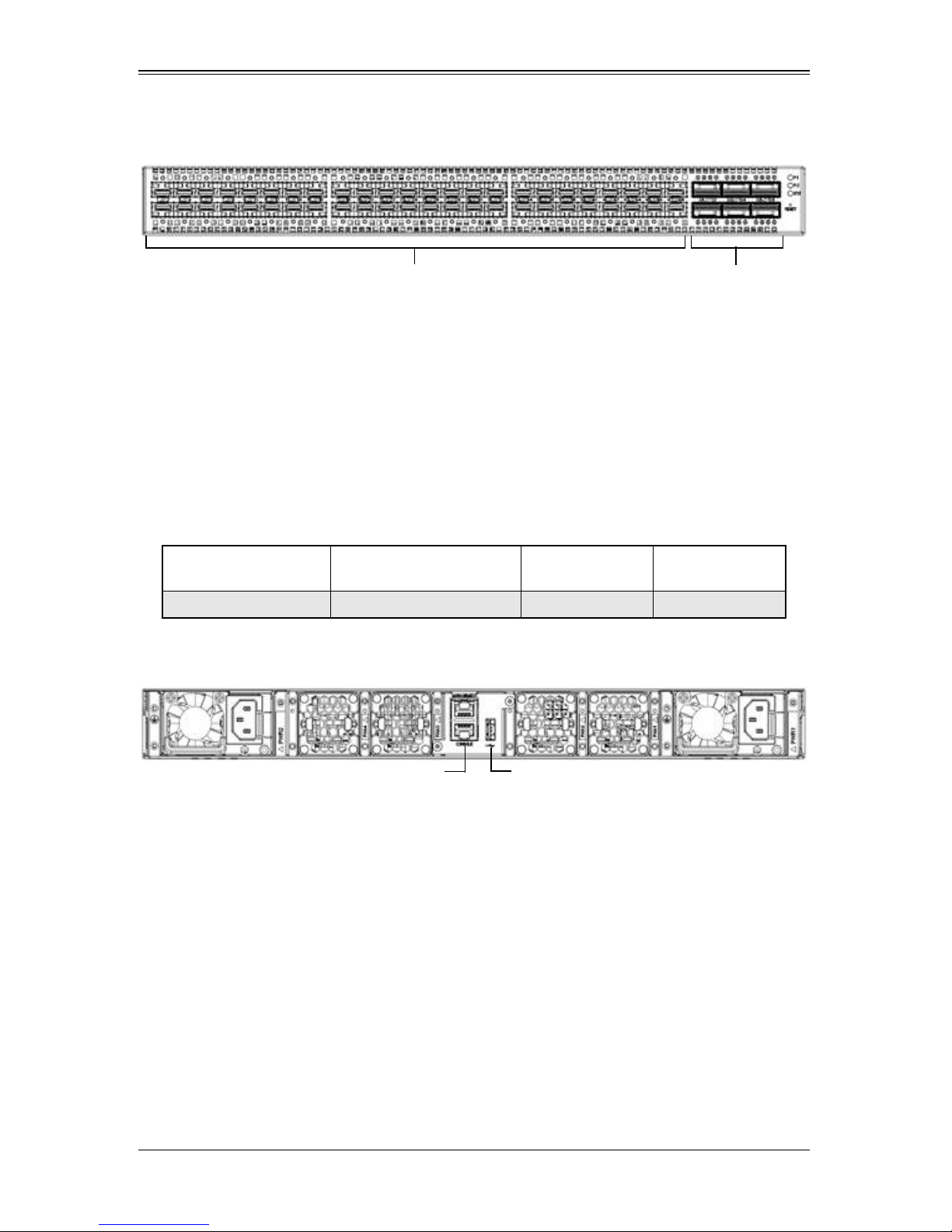
The front panel of the SSE-X3648S/SSE-X3648SR switches is shown below:
1-1
SSE-X3648S/SSE-X3648SR Switch Installation Manual
SFP+ Ports QSFP+ Ports
Power
Supply
Console Ports
Fans
Power
Supply
Fans
USB Port
Figure 1-1. Front Panel of the SSE-X3648S/SSE-X3648SR Switches
Back Panel
The SSE-X3648S/SSE-X3648SR switches provides an RJ-45 serial console port in the
rear of the switch. Users perform the local and telnet configuration through this port.
The back panel of the SSE-X3648S/SSE-X3648SR switch also includes two redundant
hot-swappable AC power supply modules, four fans and one rear panel card.
The console port supports asynchronous mode. To set this up just set the data bit as 8,
the stop bit as 1, the parity bit as none, and the default baud rate as 115,200bps.
Table 1-2. Rear Panel Descriptions of the SSE-X3648S/SSE-X3648SR Switch
Type
SSE-X3648S 1 1 1
10/100/1000Base-T
Ethernet Port
Console Port
Figure 1-2. Back Panel of the SSE-X3648S/SSE-X3648SR Switch
Cautions:
1. The USB port on the rear panel card only supports data transmission. It does not
support power supply over USB.
2. The rear panel card does not support hot plug.
3. Replacement of the rear panel card must be done by a professional.
USB2.0
Interface
1-3 Status LEDs
There are indicator LEDs on the front panel of the SSE-X3648S/SSE-X3648SR
switches. There are 48 SFP+ Port Indicator LEDs, 24 QSFP+ Port Indicator LEDs, two
Power Supply Indicator LEDs, and a System Automatic Diagnosis LED. These LEDs
are described below in Table 1-3, Table 1-4 and Table 1-5.
1-2
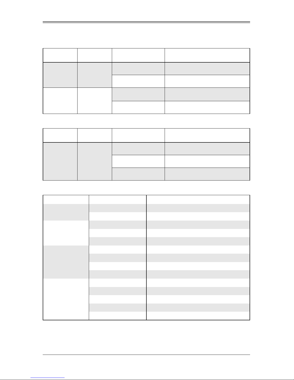
Table 1-3. Front Panel Status LEDs
Chapter 1: Introduction
Indicator
Light
Power Supply
Indicator Light
System Status
Indicate Led
Indicator
Light
Fan Module
Indicator Light
Front Panel
Sign
P-1/P-2
Start
Tab le 1-4. Rear Panel Status LEDs
Rear Panel
Sign
Fan1/Fan2/
Fan3/Fan4
Table 1-5. Port Indicator LEDs
State Description
Green light always on Power supply module operating normally.
No Light No power supply or error.
Green light always on
No Light The system is powered off.
The system is powered on and running
normally.
State Meanings
Green Light Always On Fan module is operating normally.
Red Light Always On No fan module or fan speed is 0
No Light Fan module is powered off
Indicator Light Panel Sign State
Ethernet Port Link
Light (Left)
Ethernet Port Activity
Light (Right)
Indicator Light Of
SFP+ Port
Indicator Light Of
QSFP+ Port
Green Light Wink The port is transmitting data.
Put Out There is no data transmitting on the port.
Yellow Light Always On The port is configured at 10m/100M speed
Green Light Always On The port is configured at 1000M speed
Put Out No connection or fail to connect.
Green Light Always On The port is connected at 10G.
Amber Light Always On The port is connected at 1G.
Wink The port is transmitting data.
Put Out No connection or fail to connect.
Green Light Always On The port is connected at 40G.
Amber Light Always On The port is connected at 4X10G.
Wink The port is transmitting data.
Red Light Always On There is a fault on the port.
Put Out No connection or fail to connect.
1-3
SSE-X3648S/SSE-X3648SR Switch Installation Manual
1-4 Port Description
The SSE-X3648S/SSE-X3648SR provides 48 10Gb SFP+ ports and 6 40Gb QSFP+
ports.
The following SFP transceivers are supported:
• SFP-SX-L transceiver
• SFP-LX-L transceiver
• SFP-LX-20-L 20-km transceiver
• SFP-LX-40 40-km mid distance transceiver
• SFP-LH-70-L 70-km long distance transceiver
• SFP-LH-120-L 120-km long distance transceiver
• SFP-GT 1000 Base-T SFP interface cards module
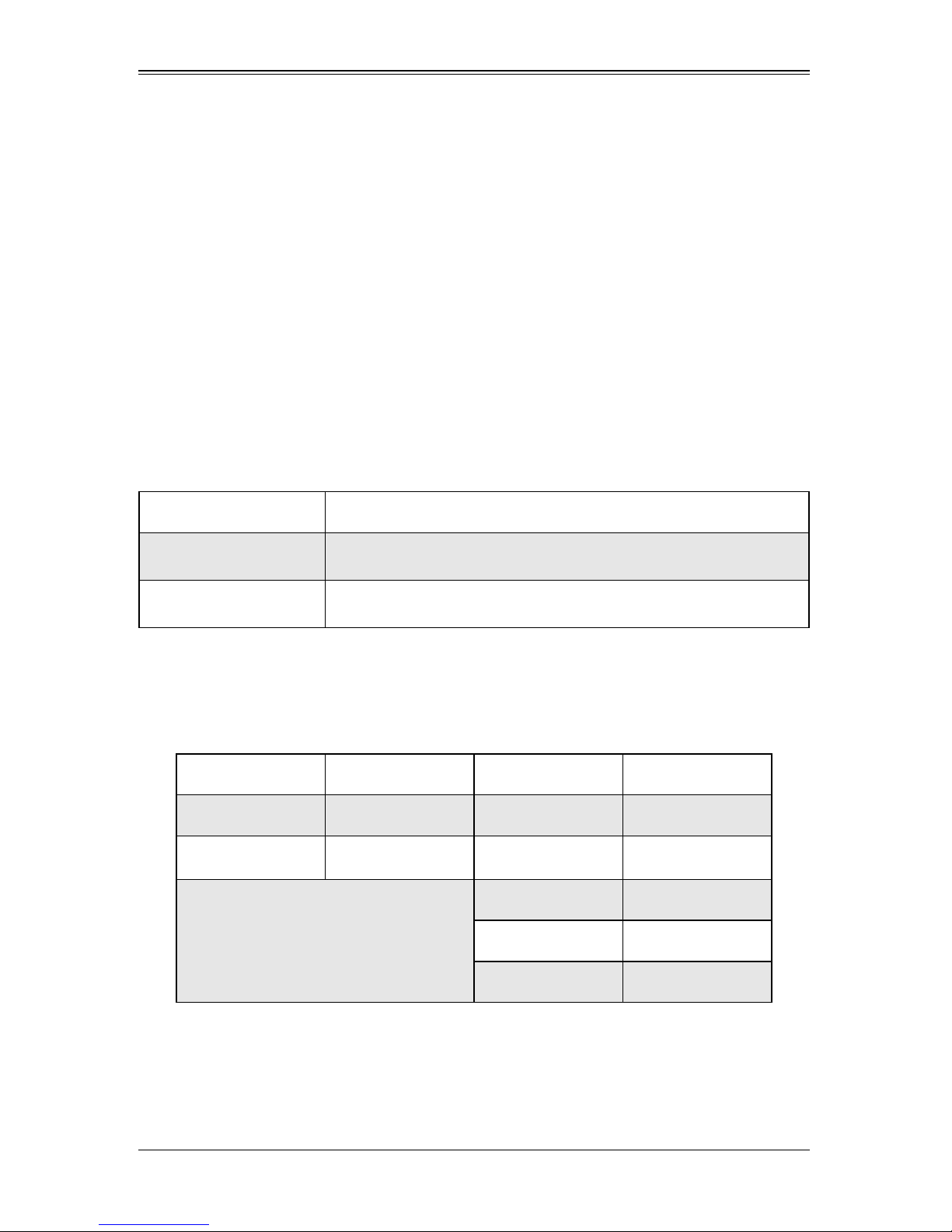
Table 1-6 describes the ports.
Table 1-6. SSE-X3648S/SSE-X3648SR Switch Port Description
Port Mode Spec
RJ-45 Port
QSFP+
• 10/100/1000Mbps Auto Negotiation
• MDI/MDI-X Cable Mode Auto Negotiation
• 40GBASE-CR4 Transceiver, Copper, 7m
• 40GBASE-SR4 Transceiver, 850nm, MMF, OM3/OM4, 100m
The SSE-X3648S/SSE-X3648SR switch provides six QSFP+ ports and supports
QSFP+ cabling. Users can select from the cables in the Table 1-7 according to their
need.
Table 1-7. Cables Supported by the SSE-X3648S/SSE-X3648SR Switch
Type Manufacturer Model St andard
40G QSFP+ Cable Tyco 2053638-3 30AWG, 3.0m
QSFP+ to 4Xsfp+
Cable
QSFP to QSFP Cable
Molex
Amphenol 582410007 30AWG, 3.0m
747571051 30AWG, 0.5m
747571101 30AWG, 1.0m
747571301 30AWG, 3.0m
1-4
Chapter 1: Introduction
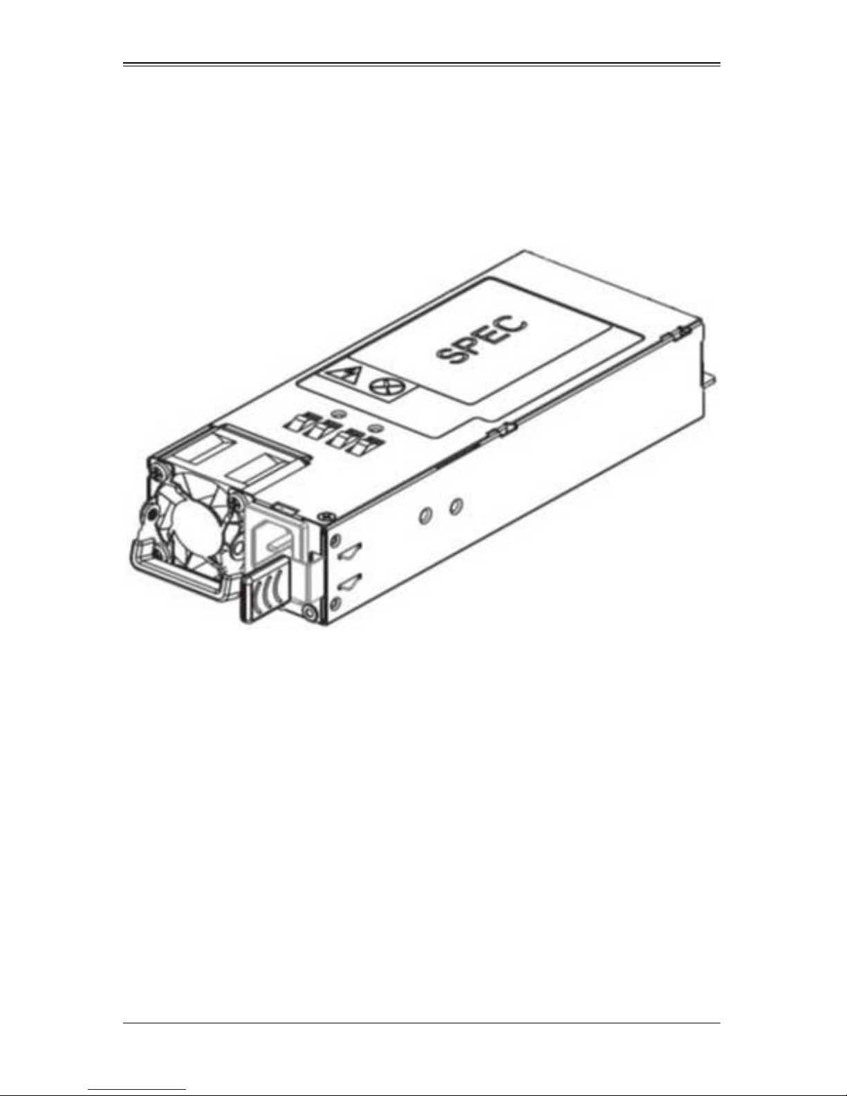
1-5 Power Supply Module
460W Power Module
Figure 1-3 shows the power supply module for the SSE-X3648S/SSE-X3648SR switch.
Figure 1-3. 460W Power Supply Module
The SSE-X3648S/SSE-X3648SR switch has two power supply modules, thus providing
redundancy. It provides airflow front to back (SSE-X3648S) or airflow back to front
(SSE-X3648SR).
The maximum power is 460W, while the input is 100VAC~240VAC, and the output is
12V +/- 5%. There is a fan and a handle for inserting or removing the module on the
back of the power supply. The power supply module supports hot-plug replacement.
1-5
SSE-X3648S/SSE-X3648SR Switch Installation Manual
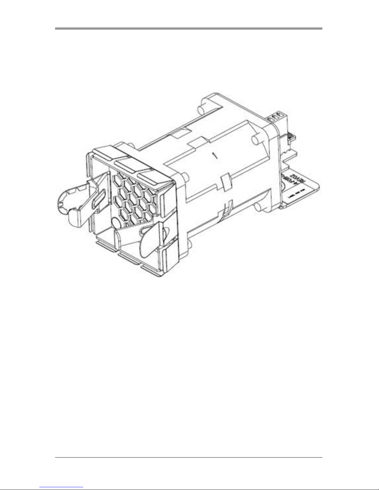
1-6 Fan Module
Figure 1-4 shows the fan module for the SSE-X3648S/SSE-X3648SR switch.
Figure 1-4. Fan Module
The SSE-X3648S/SSE-X3648SR switch has four fan modules in its standard
configuration. The rotation speed of the fan self-adjusts to adapt to system temperature,
and provides airflow front to back (SSE-X3648S) and airflow back to front
(SSE-X3648SR).
Cautions:
1. Different airflow fan modules cannot be mixed.
2. Airflow for power modules must be the same as that used for fan modules.
1-6
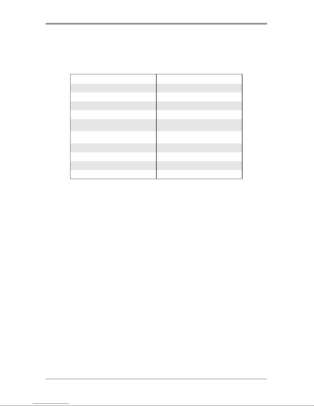
1-7 System Specifications
System specifications are shown in Table 1-8 below.
Table 1-8. System Specifications
Specification Description
Dimensions(W * H * D) (mm) 433.8 * 44 * 550
Weight 10.133 kg
Fixed Port 48 SFP+ ports; 6 QSFP+ ports
Management Port 1 RJ-45 serial console port
Power Input 100~240VAC(50~60Hz) 2.8A~5.6A
System Power Consumption <400W
Operating Temperature 0°C~40°C
Storage Temperature -40°C~75°C
Operating Relative Humidity 10%~90%, no condensate
Chapter 1: Introduction
Storage Relative Humidity 5%~95%, no condensate
1-7

SSE-X3648S/SSE-X3648SR Switch Installation Manual
Notes
1-8
 Loading...