

Supermicro SSE-G3648B, SSE-G3648BR Installation Manual

SSE-G3648B/BR Switch Installation Guide
Page 1
SSE-G3648B
SSE-G3648BR
Switch Installation Guide
Revision 1.0

SSE-G3648B/BR Switch Installation Guide
Page 2
The information in this Installation Manual has been carefully reviewed and is believed to be accurate. The vendor assumes no
responsibility for any inaccuracies that may be contained in this document, makes no commitment to update or to keep current the
information in this manual, or to notify any person or organization of the updates. Ple ase Note: For th e mo st up-to-date version of
this manual, please see our web site at www.supermicro.com.
Super Micro Computer, Inc. (“Supermicro”) reserves the right to make changes to the product described in this manual at any time
and without notice. This product, including software, if any, and documentation may not, in whole or in part, be copied, photocopied,
reproduced, translated or reduced to any medium or machine without prior written consent.
IN NO EVENT WILL SUPERMICRO BE LIABLE FOR DIRECT, INDIRECT, SPECIAL, INCIDENTAL, SPECULATIVE OR
CONSEQUENTIAL DAMAGES ARISING FROM THE USE OR INABILITY TO USE THIS PRODUCT OR DOCUMENTATION, EVEN
IF ADVISED OF THE POSSIBILITY OF SUCH DAMAGES. IN PARTICULAR, SUPERMICRO SHALL NOT HAVE LIABILITY FOR
ANY HARDWARE, SOFTWARE, OR DATA STORED OR USED WITH THE PRODUCT, INCLUDING THE COSTS OF REPAIRING,
REPLACING, INTEGRATING, INSTALLING OR RECOVERING SUCH HARDWARE, SOFTWARE, OR DATA.
Any disputes arising between manufacturer and customer shall be governed by the laws of Santa Clara County in the State of
California, USA. The State of California, County of Santa Clara shall be the exclusive venue for the resolution of any such disputes.
Super Micro's total liability for all claims will not exceed the price paid for the hardware product.
FCC Statement: This equipment has been tested and found to comply with the limits for a Class A digital device pursuant to Part 15 of
the FCC Rules. These limits are designed to provide reasonable protection against harmful interference when the equipment is
operated in a commercial environment. This equipment generates, uses, and can radiate radio frequency energy and, if not installed
and used in accordance with the manufacturer’s instruction manual, may cause harmful interference with radio communications.
Operation of this equipment in a residential area is likely to cause harmful interference, in which case you will be required to correct
the interference at your own expense.
California Best Management Practices Regulations for Perchlorate Materials: This Perchlorate warning applies only to products
containing CR (Manganese Dioxide) Lithium coin cells. Perchlorate Material-special handling may apply. See
www.dtsc.ca.gov/hazardouswaste/perchlorate for further details.
WARNING: HANDLING OF LEAD SOLDER MATERIALS USED IN THIS PRODUCT MAY EXPOSE YOU TO LEAD,
A CHEMICAL KNOWN TO THE STATE OF CALIFORNIA TO CAUSE BIRTH DEFECTS AND OTHER
REPRODUCTIVE HARM.
Manual Revision 1.0
Release Date: June 7, 2016 3:44 PM
Unless you request and recei ve wri tt en perm i ssion from Super Micro Computer, Inc., you may not copy any part of this document.
Information in this document is subject to change without notice. Other products and companies referred to herein are trademarks or
registered trademarks of their respective companies or mark holders.
Copyright © 2016 by Super Micro Computer, Inc.
All rights reserved.
Printed in the United States of America

SSE-G3648B/BR Switch Installation Guide
Page 3
Contents
1. Introduction .............................................................................................5
Overview ............................................................................................................. 5
Description of Hardware ..................................................................................... 6
Front Panel................................................................................................................. 6
Back Panel ................................................................................................................. 6
Status LEDs .......................................................................................................... 7
Port Description ................................................................................................... 8
Power Supply Module ....................................................................................... 10
Fan Module .......................................................................................................... 11
System Specifications........................................................................................ 11
2. Standardized Warning Statements ...................................................... 12
About Standardized Warning Statements ....................................................... 12
Warning Defini tion .................................................................................................. 12
Installation Instructions .......................................................................................... 15
Circuit Breaker ........................................................................................................ 16
Power Disconnection Warning .............................................................................. 17
Equipment Installation ............................................................................................ 19
Restricted Area ........................................................................................................ 20
Battery Handling ..................................................................................................... 21
Comply with Local and National Electrical Codes .............................................. 22
Product Disposal ..................................................................................................... 23
Power Cable and AC Adapter ................................................................................. 24
3. Installation Requirements .................................................................... 27
Environmental Requirements ........................................................................... 27
Dust and Particles ................................................................................................... 27
Temperature and Humidity ..................................................................................... 28
Power Supply .......................................................................................................... 29
Preventing Electrostatic Discharge Damage ....................................................... 29
Anti-interference ..................................................................................................... 29
Installation Notice .............................................................................................. 30
Security Warnings ............................................................................................. 31
4. Device Installation ................................................................................ 32
Installation Preparation ..................................................................................... 32
Verify the Package Contents .................................................................................. 32
Required Tools and Utilities ................................................................................... 32
Device Installation ............................................................................................. 33

SSE-G3648B/BR Switch Installation Guide
Page 4
Installing the Switch ............................................................................................... 33
Installing the main Power Supply Module ............................................................ 34
Installing the Second Power Supply Module ....................................................... 34
Installing the Fan ..................................................................................................... 36
Connecting the Console ......................................................................................... 37
SFP/SFP+ Transceiver Installation ........................................................................ 38
Copper Cable/Fiber Cable Connection ................................................................. 38
AC Power Supply Connection ............................................................................... 40
Checking the Switch ............................................................................................... 41
SSE-G3648B/BR Switch Installation Guide
Page 5
1. Introduction
Overview
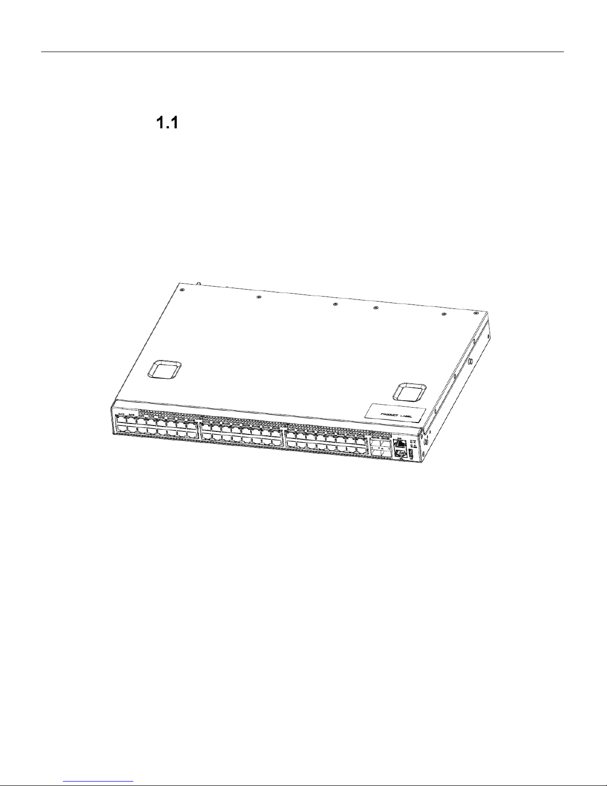
The Supermicro SSE-G 3648B and SSE-G3648BR are a new generation of 1/10G Ethernet
aggregation switches. They offer 1G Ethernet connectivity for servers and end users as well as
access to 10G backbone networks and/or servers with higher speed connectivity. The available
redundant power supp l y option is bu t on e of the many features mak ing them attractive for use
in the modern data center. T hey are ideal as a distribution layer s witch for campus networks,
enterprise network s and High Performance (H P) networks; as well as a core l ayer switch for
small to medium-sized networ ks. Preloaded with Op en Networking Installation Environm ent
(ONIE) they are particularly suitable for use in an Open Networking environment.
Figure 1-1 SSE-G3648B/BR Switches
SSE-G3648B/BR Switch Installation Guide
Page 6
Description of Hardware
Front Panel
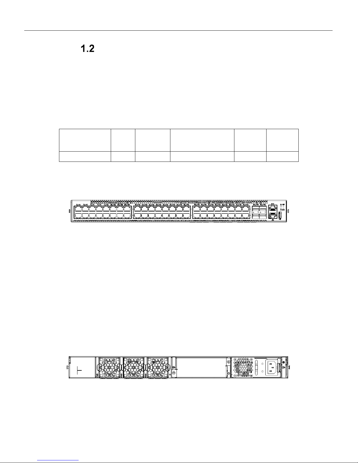
1. Front Panel Diagram
The front panel descriptions of the SSE-G3648B/BR switches are given in the following table:
Table 1-1: Front Panel Descriptions of SSE-G3648B/BR Switches
Type
RJ45
Port
SFP+ Port
10/100/1000Base-T
ETHERNET Port
Console
Port
USB 2.0
Interface
SSE-G3648B/BR
48
4 1 1
1
The front panel of SSE-G3648B/BR is shown below:
Figure 1-2: Front Panel of SSE-G3648B/BR Switches
2. Console description
SSE-G3648B/BR switches provide an RJ-45 serial cons ole port. Users can perform the local
and telnet configuration through this port.
The console port supports asynchronous mode Set the data bit as 8, the stop bit as 1, the parity
bit as none, and the default baud rate as 115200bps.
Back Panel
The back panel of SSE-G3648B/BR switches includes one 90~264VAC, 47Hz~63Hz power
supply. An optional additional power supply provides redundancy. There are three fans.
Fig 1-3: Back Panel SSE-G3648B/BR (Standard Configuration)
SSE-G3648B/BR Switch Installation Guide
Page 7
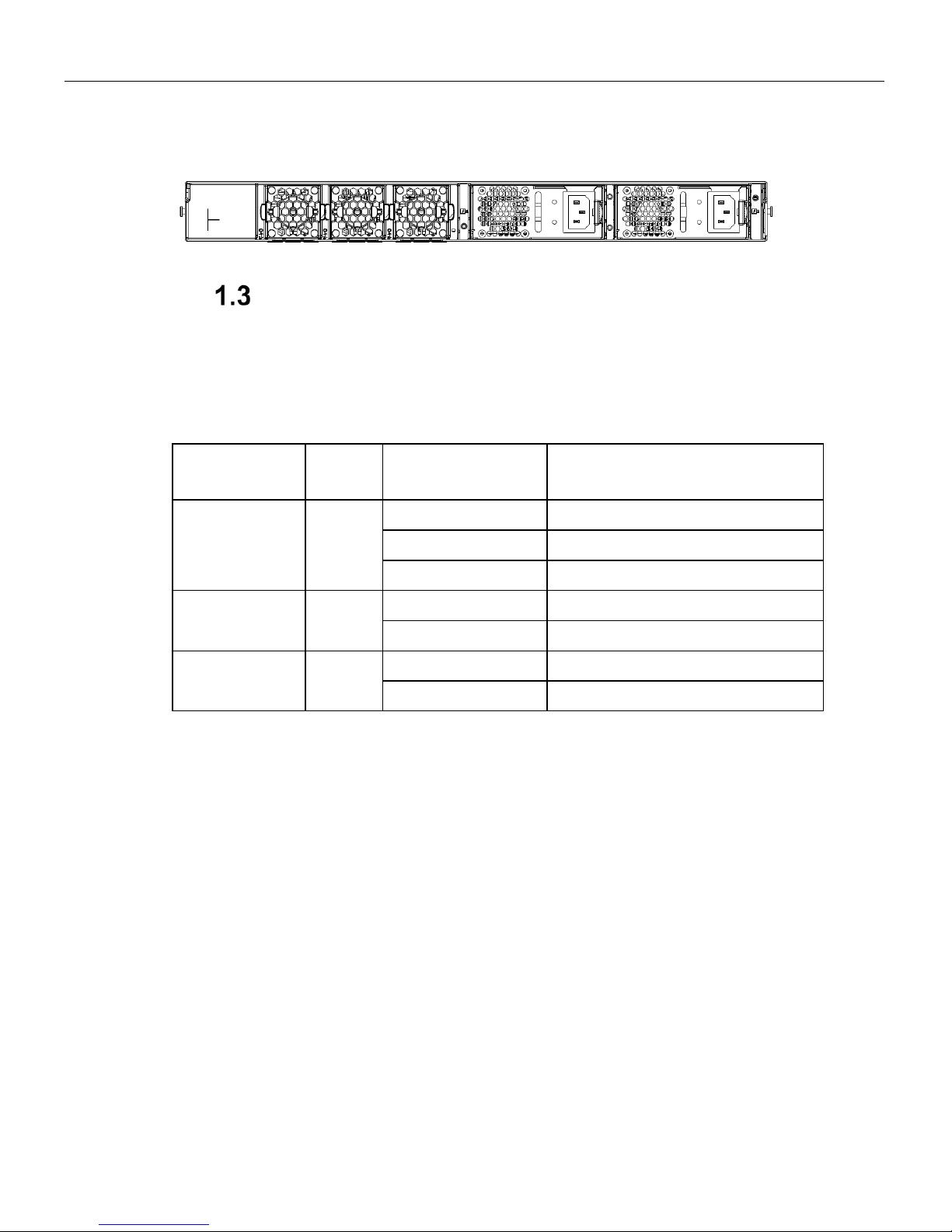
Fig 1-4: Back panel of SSE-G3648B/BR
(with Second Power Supply Installed)
Status LEDs
The indicator light on fr ont panel of the SSE-G3648B/BR has forty-eight RJ45 port indicator
lights, four SFP+ port indicator lights, two power supply indicator lights and a system automatic
diagnostics LED. They are shown below and described in the following table.
Table 1-2: Explanation of Indicator Light of SSE-G3648B/BR Switch
Indicator Light Panel
Sign
State Meanings
Power Supply
Indicator Light
P-1 / P-2
Green light always on
Power supply module move normally
Amber light always on
Power fault
No light
No power supply
System Automatic
Diagnostic LED
STAT
Green light always on
System running norm ally
Green light blinks
System booting
Work Mode
Indicator Light
MAST
Green light always on
Master mode
Amber light always on
Slave mode
SSE-G3648B/BR Switch Installation Guide
Page 8
Table 1-3: Explanation of the Port Indicator Light
Indicator Light Panel Sign State
ETHERNET Port
Link Light (Right)
Green
The port is under the connection state of 10M, 100M or
1000M
Blinking Green
The port is transmitting data
No light
No connection or fail to connect
Indicator Light of
SFP+ Port
Green
The port is under the connection state of 1G/10G
Blinking Green
The port is transmitting data
No light
No connection or fail to connect
Indicator Light of
RJ45 Port
Green
The port is connected at 1G
Amber
The port is connected at of 10M/100M
Blinking Green
The 1G port is transmitting data
Blinking Amber
The 10M/100M port transmitti ng data
No light
No connection or fail to connect
Port Description
The SSE-G3648B/BR provide forty-eight RJ45 ports and four 10 Gb SFP+ ports.
SSE-G3648B/BR series switches support the following SFP transceivers:
• SFP-SX-L transceiver
• SFP-LX-L transceiver
• SFP-LX-20-L 20 km transceiver
• SFP-LX-40 40 km mid distance transceiver
• SFP-LH-70-L 70 km long distance transceiver
• SFP-LH-120-L 120 km long distance transceiver
• SFP-GT 1000 Base-T SFP interface cards module

SSE-G3648B/BR Switch Installation Guide
Page 9
Each port is described below:
Table 1-4: SSE-G3648B/BR Port Description
Port Mode Spec
RJ-45 port 10/100/1000Mbps auto negotiation
MDI/MDI-X cable mode auto negotiation
5 kinds of UTP: 100 m
SFP
SFP-SX-L transceiver
1000Base-SX SFP(850nm,MMF,550m)
SFP-LX-L transceiver
1000Base-LX SFP(1310nm, SMF, 10km or MMF, 550m)
SFP-LX-20-L transceiver
1310nm light wave, 9/125um single mode fiber: 20km
SFP-LX-40 transceiver
9/125um single mode fiber: 40km
SFP-LH-70-L transceiver
9/125um single mode fiber: 70km
SFP-LH-120-L transceiver
9/125um single mode fiber: 120km
SSE-G3648B/BR switches provide 4 SFP+ ports. In addition to support of optical fiber
connections through transceivers, they support SFP+ Direct Attach Copper (DAC) cables
(0.5M-7M). This provides enhanced flexibility in network design and installation.
SSE-G3648B/BR Switch Installation Guide
Page 10
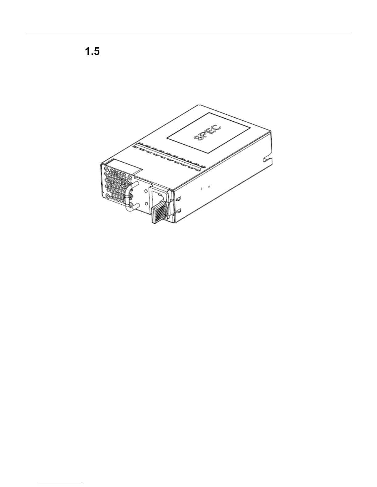
Power Supply Module
The following picture is the power supply module (PSM) of SSE-G3648B/BR.:
Fig 1-5: SSE-G3648B/BR PSM
SSE-G3648B/BR switches have one PSM in the standard configuration. When two power
supplies are installed, they give power redundancy.
The maximum input power is 200W @ 90VAC~264VAC/47HZ~63HZ. Output is 12V +/- 5%.
There is a fan and a handle for ins erting or removing the m odule on the back of the power
supply. The power supply module supports hot plug.
SSE-G3648B/BR Switch Installation Guide
Page 11
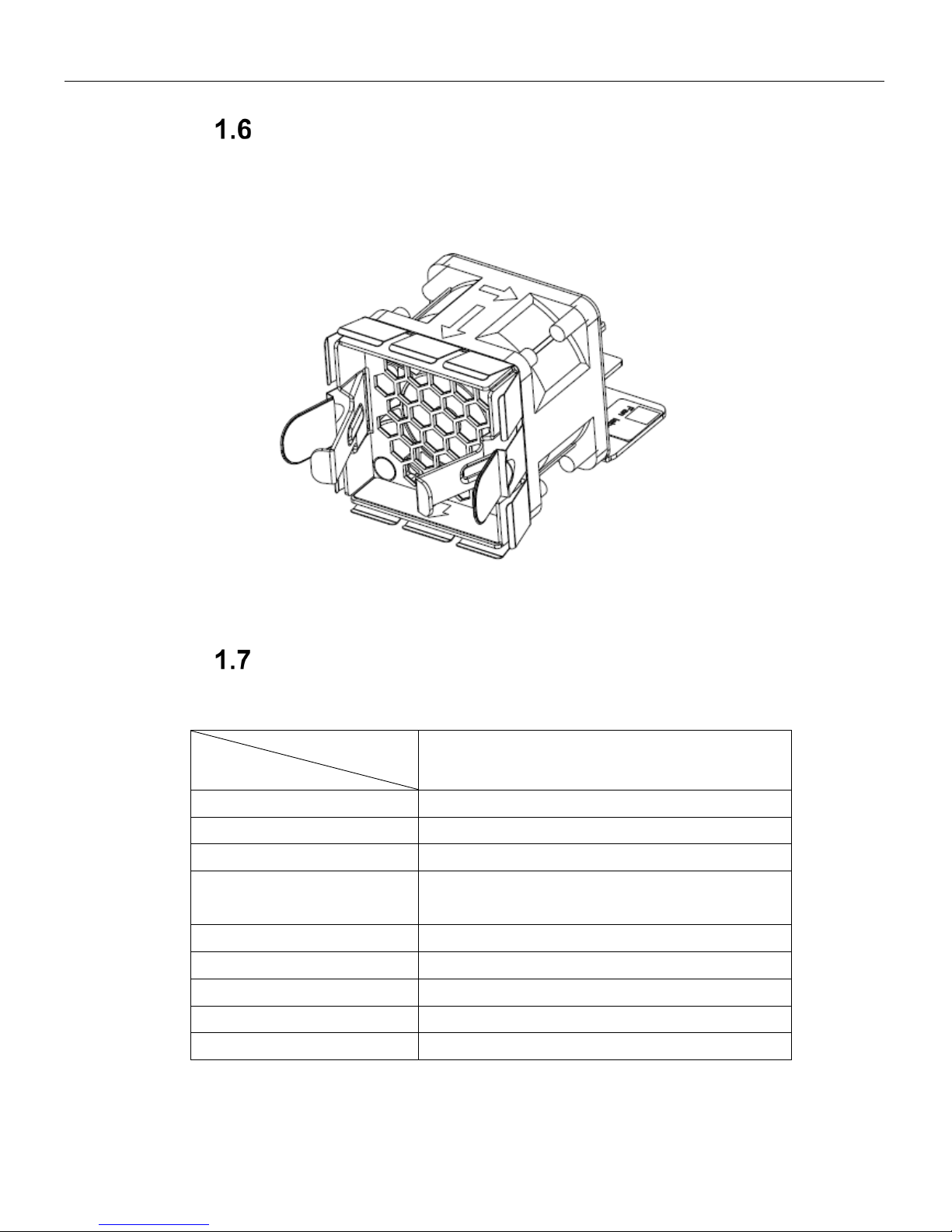
Fan Module
The SSE-G3648B/BR series fan module is shown below:
Fig 1-6: Fan Module
SSE-G3648B/BR switches have three fan modules. The rotation speed of the fan is selfadjusting, based upon system temperature, and supports hot plug.
System Specification s
Table 1-5: System Specifications of SSE-G3648B/BR Switches
Type
Attribute
E1031
Dimension(W * H * D) (mm)
320×434×44
Weight
5.6 kg (standard: one power)
Fixed Port
48 RJ45 ports; 4 SFP+ ports
Management Port 1 RJ-45 serial console port
1 RJ-45 management Ethernet port
Power Input
90~264VAC(47~63Hz)
System Consumption
<100W
Operating Temperature
0°C~45°C
Storage Te mperature
-40°C~70°C
Relative Humidity
5%~85%, no condensing
SSE-G3648B/BR Switch Installation Guide
Page 12
2. Standardized Warning Statements
About Standardized Warning
Statements
The following statements are industry standard warnings, provided to warn the user of
situations which have the potential for bodily injury. Should you have questions or experience
difficulty, contact Supermicro's Technical Support department for assistance. Only certified
technicians should attempt to install or configure components.
Read this appendix in its entirety before installing or configuring components in the
Supermicro chassis
These warnings may also be found on our web site at
http://www.supermicro.com/about/policies/safety_information.cfm
Warning Definition
Warning!
This warning symbol means danger. You are in a situation that could cause bodily injury.
Before you work on any equipment, be aware of the hazards involved with electrical circuitry
and be familiar with standard practices for preventing accidents.
警告の定義
この警告サインは危険を意味します。
人身事故につながる可能性がありますので、いずれの機器でも動作させる前に、
電気回路に含まれる危険性に注意して、標準的な事故防止策に精通して下さい。

SSE-G3648B/BR Switch Installation Guide
Page 13
此警告符号代表危险。
您正处于可能受到严重伤害的工作环境中。在您使用设备开始工作之前,必须充分意识到触电
的危险,并熟练掌握防止事故发生的标准工作程序。请根据每项警告结尾的声明号码找到此设
备的安全性警告说明的翻译文本。
此警告符號代表危險。
您正處於可能身體可能會受損傷的工作環境中。在您使用任何設備之前,請注意觸電的危險,
並且要熟悉預防事故發生的標準工作程序。請依照每一注意事項後的號碼找到相關的翻譯說明
內容。
Warnung
WICHTIGE SICHERHEITSHINWEISE
Dieses Warnsymbol bedeutet Gefahr. Sie befinden sich in einer Situation, die zu
Verletzungen führen kann. Machen Sie sich vor der Arbeit mit Geräten mit den Gefahren
elektrischer Schaltungen und den üblichen Verfahren zur Vorbeugung vor Unfällen vertraut.
Suchen Sie mit der am Ende jeder Warnung angegebenen Anweisungsnummer nach der
jeweiligen Übersetzung in den übersetzten Sicherheitshinweisen, die zusammen mit diesem
Gerät ausgeliefert wurden.
BEWAHREN SIE DIESE HINWEISE GUT AUF.
INSTRUCCIONES IMPORTANTES DE SEGURIDAD
Este símbolo de aviso indica peligro. Existe riesgo para su integridad física. Antes de
manipular cualquier equipo, considere los riesgos de la corriente eléctrica y familiarícese con
los procedimientos estándar de prevención de accidentes. Al final de cada advertencia
encontrará el número que le ayudará a encontrar el texto traducido en el apartado de
traducciones que acompaña a este dispositivo.
GUARDE ESTAS INSTRUCCIONES.
IMPORTANTES INFORMATIONS DE SÉCURITÉ
Ce symbole d'avertissement indique un danger. Vous vous trouvez dans une situation
pouvant entraîner des blessures ou des dommages corporels. Avant de travailler sur un
équipement, soyez conscient des dangers liés aux circuits électriques et familiarisez-vous
avec les procédures couramment utilisées pour éviter les accidents. Pour prendre
connaissance des traductions des avertissements figurant dans les consignes de sécurité
traduites qui accompagnent cet appareil, référez-vous au numéro de l'instruction situé à la fin
de chaque avertissement.
CONSERVEZ CES INFORMATIONS
 Loading...