

Supermicro SSE-G3632S, SSE-G3632SR Installation Manual
Supermicro SSE-C3632S/SSE-C3632SR Switch Installation Guide
Page 1
SSE-G3632S
SSE-G3632SR
Switch Installation Guide
Revision 1.0

Supermicro SSE-C3632S/SSE-C3632SR Switch Installation Guide
Page 2
The information in this Installation Manual has been carefully reviewed and is believed to be accurate. The vendor assumes no responsibility for
any inaccuracies that may be contained in this document, makes no commitment to update or to keep current the information in this manual, or to
notify any person or organization of the updates. Please Note: For the most up-to-date version of this manual, please see our web site at
www.supermicro.com.
Super Micro Computer, Inc. (“Supermicro”) reserves the right to make changes to the product described in this manual at any time and without
notice. This product, including software, if any, and documentation may not, in whole or in part, be copied, photocopied, reproduced, translated or
reduced to any medium or machine without prior written consent.
IN NO EVENT WILL SUPERMICRO BE LIABLE FOR DIRECT, INDIRECT, SPECIAL, INCIDENTAL, SPECULATIVE OR CONSEQUENTIAL
DAMAGES ARISING FROM THE USE OR INABILITY TO USE THIS PRODUCT OR DOCUMENTATION, EVEN IF ADVISED OF THE
POSSIBILITY OF SUCH DAMAGES. IN PARTICULAR, SUPERMICRO SHALL NOT HAVE LIABILITY FOR ANY HARDWARE, SOFTWARE, OR
DATA STORED OR USED WITH THE PRODUCT, INCLUDING THE COSTS OF REPAIRING, REPLACING, INTEGRATING, INSTALLING OR
RECOVERING SUCH HARDWARE, SOFTWARE, OR DATA.
Any disputes arising between manufacturer and customer shall be governed by the laws of Santa Clara County in the State of California, USA.
The State of California, County of Santa Clara shall be the exclusive venue for the resolution of any such disputes. Super Micro's total liability for
all claims will not exceed the price paid for the hardware product.
FCC Statement: This equipment has been tested and found to comply with the limits for a Class A digital device pursuant to Part 15 of the FCC
Rules. These limits are designed to provide reasonable protection against harmful interference when the equipment is operated in a commercial
environment. This equipment generates, uses, and can radiate radio frequency energy and, if not installed and used in accordance with the
manufacturer’s instruction manual, may cause harmful interference with radio communications. Operation of this equipment in a residential area
is likely to cause harmful interference, in which case you will be required to correct the interference at your own expense.
California Best Management Practices Regulations for Perchlorate Materials: This Perchlorate warning applies only to products containing CR
(Manganese Dioxide) Lithium coin cells. Perchlorate Material-special handling may apply. See www.dtsc.ca.gov/hazardouswaste/perchlorate for
further details.
WARNING: HANDLING OF LEAD SOLDER MATERIALS USED IN THIS PRODUCT MAY EXPOSE YOU TO LEAD, A CHEMICAL KNOWN TO
THE STATE OF CALIFORNIA TO CAUSE BIRTH DEFECTS AND OTHER REPRODUCTIVE HARM.
Manual Revision 1.0
Release Date: April 5, 2017 3:47 PM
Unless you request and receive written permission from Super Micro Computer, Inc., you may not copy any part of this document.
Information in this document is subject to change without notice. Other products and companies referred to herein are trademarks or registered
trademarks of their respective companies or mark holders.
Copyright © 2017 by Super Micro Computer, Inc.
All rights reserved.
Printed in the United States of America

Supermicro SSE-C3632S/SSE-C3632SR Switch Installation Guide
Page 3
Preface
About this Manual
This manual is written for professional system integrators, Information Technology professionals,
service personnel, technicians and network administrators who are responsible for installing and setting
up network equipment; consequently, it assumes a basic working knowledge of LANs (Local Area
Networks). It provides information for the installation and use of the Supermicro's SSE-G3632R and
SSE-G3632SR switches. Installation and maintenance should be performed by experienced
professionals only.
Manual Organization
Chapter 1: Introduction
The first chapter provides an introduction to the switch.
Chapter 2: Safety
The second chapter provides important safety information for the switch.
Chapter 3: Installation Requirements
This chapter covers installation requirements, notices and security warnings for the switches.
Chapter 3 Device Installation
Use this chapter for installation of the switches and connecting them to your systems.

Supermicro SSE-C3632S/SSE-C3632SR Switch Installation Guide
Page 4
Table of Contents
Introduction .............................................................................................................................. 6
1.1 Overview ....................................................................................................................................................... 6
1.2 Features and Benefits ................................................................................................................................... 7
Various Interfaces ........................................................................................................................................... 7
Supports 100Gbs Ethernet .............................................................................................................................. 7
Different Airflow Options ................................................................................................................................ 7
1.3 Hardware ...................................................................................................................................................... 8
Front Panel ...................................................................................................................................................... 8
Back Panel ....................................................................................................................................................... 9
1.4 Status LEDs .................................................................................................................................................... 9
1.5 Port Description .......................................................................................................................................... 10
1.6 Power Supply Module ................................................................................................................................. 11
800W Power Module .................................................................................................................................... 11
1.7 Fan Module ................................................................................................................................................. 11
1.8 System Specifications .................................................................................................................................. 12
Standardized Warning Statements .......................................................................................... 13
2.1 About Standardized Warning Statements ............................................................................................. 13
Installation Notices ................................................................................................................. 25
3.1 Environmental Requirements ...................................................................................................................... 25
Dust and Particles ......................................................................................................................................... 25
Temperature and Humidity ........................................................................................................................... 26
Power Supply ................................................................................................................................................ 27
Preventing Electrostatic Discharge Damage ................................................................................................. 27
Anti-interference .......................................................................................................................................... 27
Rack Configuration ........................................................................................................................................ 28
3.2 Installation Notice ....................................................................................................................................... 28
3.3 Security Warnings ....................................................................................................................................... 29
Device Installation................................................................................................................... 30
4.1 Installation Preparation .............................................................................................................................. 30
Verify the Package Contents ......................................................................................................................... 30

Supermicro SSE-C3632S/SSE-C3632SR Switch Installation Guide
Page 5
Required Tools and Utilities .......................................................................................................................... 30
4.2 Device Installation ................................................................................................................................. 31
Installing the Switch ...................................................................................................................................... 31
Installation with Mounting Rails ................................................................................................................... 32
Installing the Power Supply Module ............................................................................................................. 33
Installing the Fan ........................................................................................................................................... 34
Connecting the Console ................................................................................................................................ 35
QSFP28 Transceiver Installation .................................................................................................................... 36
Copper Cable/Fiber Cable Connection ......................................................................................................... 36
AC Power Supply Connection ....................................................................................................................... 38
Grounding Cable Connection ........................................................................................................................ 39
Checking the Switch ...................................................................................................................................... 40
Supermicro SSE-C3632S/SSE-C3632SR Switch Installation Guide
Page 6
Introduction
1.1 Overview
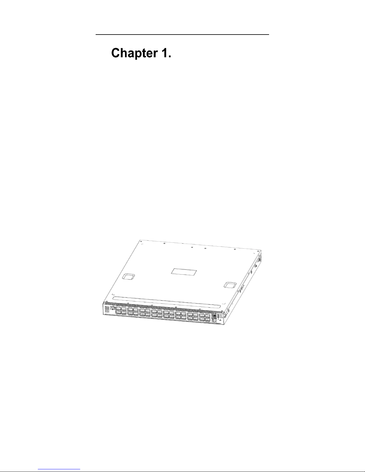
The Supermicro SSE-C3632S and SSE-C3632SRS switches are at the top of the Supermicro bare
metal switch line. A new generation of 100G Ethernet routing switches, they enable a robust layer-3 IP
fabric with a flexible layer-2 overlay in an optimized Ethernet architecture. They are well-suited to
function as the high-speed spine layer, giving scalable bi-sectional fabric bandwidth for leaf layer
switches like the SSE-X3648S or even the SSE-G3648B. The ability to configure the individual physical
Ethernet QSFP28 ports as either 40Gbps or 100Gbps, gives optimum flexibility for high-speed physical
connectivity between the spine and leaf layers in the data center Ethernet fabric.
These switches incorporate 100GE switching technology and are particularly appropriate for use in
large-scale data centers to provide 100GE server connectivity as well as high-bandwidth connectivity
to other Ethernet switching products. Redundant hot-swappable power supplies (standard) are but one
of the many features making them attractive for use in the modern data center. They are ideal as a
distribution layer switch for campus networks, enterprise networks and High Performance Computing
(HPC) networks; as well as a core layer switch for small to medium-sized networks. Preloaded with
Open Networking Installation Environment (ONIE) they are optimized for use in an Open Networking
environment.
Figure 1-1. SSE-C3632S and SSE-C3632SR Switches
Supermicro SSE-C3632S/SSE-C3632SR Switch Installation Guide
Page 7
1.2 Features and Benefits
Various Interfaces
The SSE-C3632S and SSE-C3632SR switches provide thirty-two 100Gbs QSFP28 ports. Each
QSFP28 port can be split into four 25Gbs SFP28 ports. Each QSFP28 port can alternatively be
configured at 40Gbps – which in turn can be split into four 10Gbps SFP+ ports.
Supports 100Gbs Ethernet
100Gbs Ethernet is a big leap in the evolution of Ethernet. 100Gbs Ethernet can be deployed in leafand-spine topologies. With 100Gbs Ethernet, the SSE-C3632S and SSE-C3632SR switches provide
high bandwidth and powerful processing capacity. Using SSE-C3632S and SSE-C3632SR switches,
users can simplify network structures and reduce the cost of network construction.
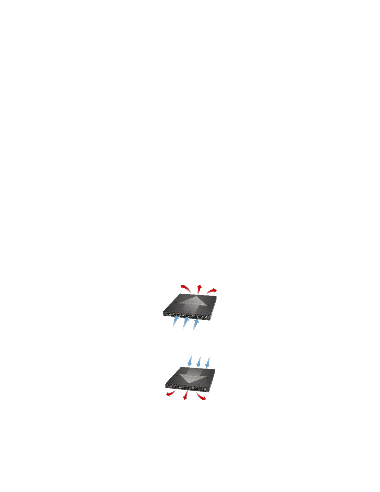
Different Airflow Options
The SSE-C3632S provides “front-to-back” air flow (port-side to power-supply side) for cooling –
sometimes called “normal air flow”. The SSE-C3632SR provides air flow in the opposite direction
(“reverse air flow”). Reverse air flow is particularly useful in data centers with alternating “hot” and
“cold” aisles because it allows the switch to be installed in the rear of a rack facing the “hot” aisle. This
is the side of the rack where networking cables are typically attached to servers.
Figure 1-2. Regular Air Flow
Figure 1-3. Reverse Air Flow
Supermicro SSE-C3632S/SSE-C3632SR Switch Installation Guide
Page 8
1.3 Hardware
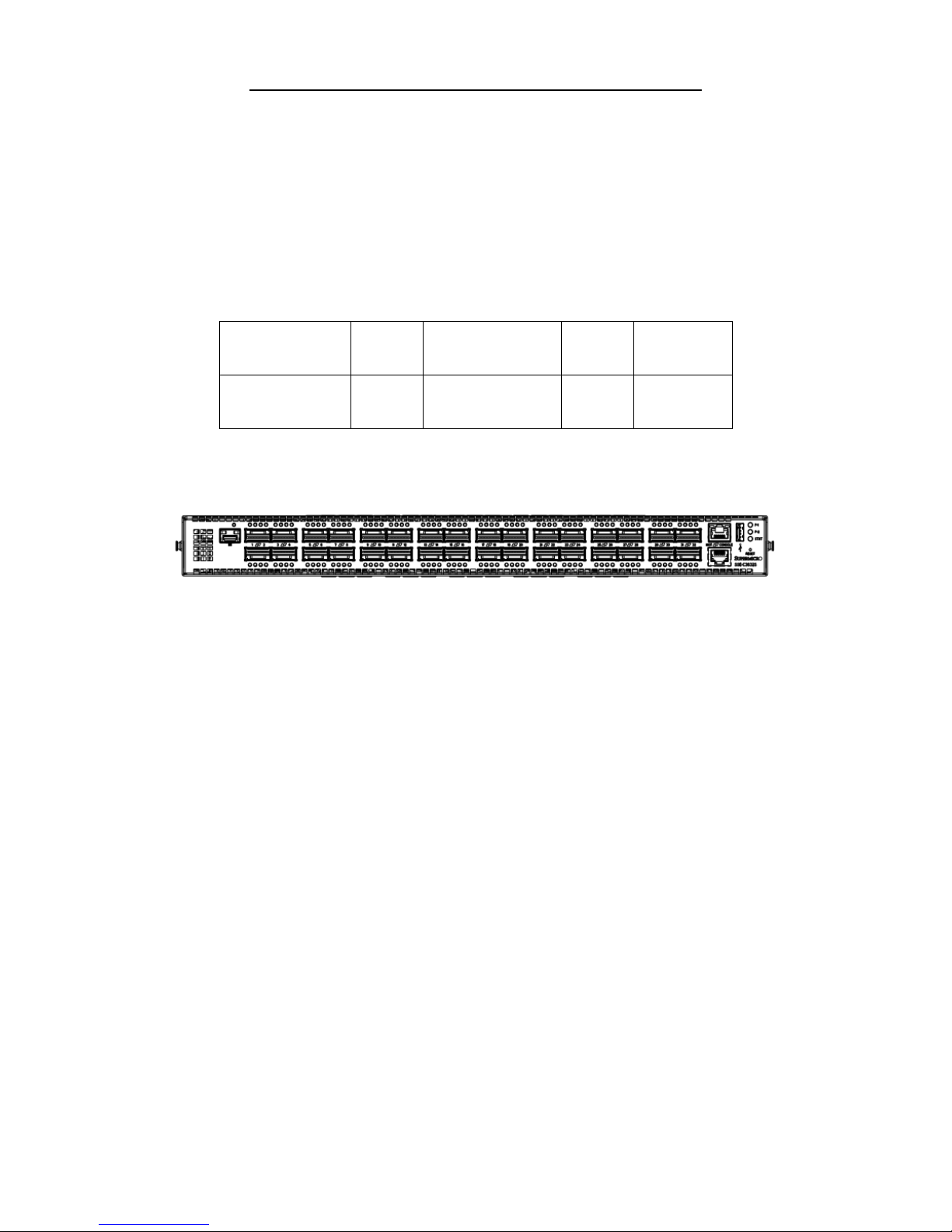
Front Panel
The front panel descriptions of SSE-C3632S and SSE-C3632SR switches are given in the following
table.
Panel Descriptions of the SSE-C3632S/SR Switches
Type
QSFP28
Port
10/100/1000Base-T
ETHERNET Port
Console
Port
USB 2.0
Interface
SSE-C3632S and
SSE-C3632SR
32 1 1
1
The front panel of the SSE-C3632S/R is shown below:
Figure 1-4. Front Panel View
Caution: The USB port only supports data transmission, it does not supply USB power.
Console Description
SSE-C3632S and SSE-C3632SR switches provide an RJ-45 serial console port. Users can perform
local and telnet configuration through this port.
The console port supports asynchronous mode: set the data bit as 8, the stop bit as 1, the parity bit as
none. The default baud rate is 115200bps.
Supermicro SSE-C3632S/SSE-C3632SR Switch Installation Guide
Page 9
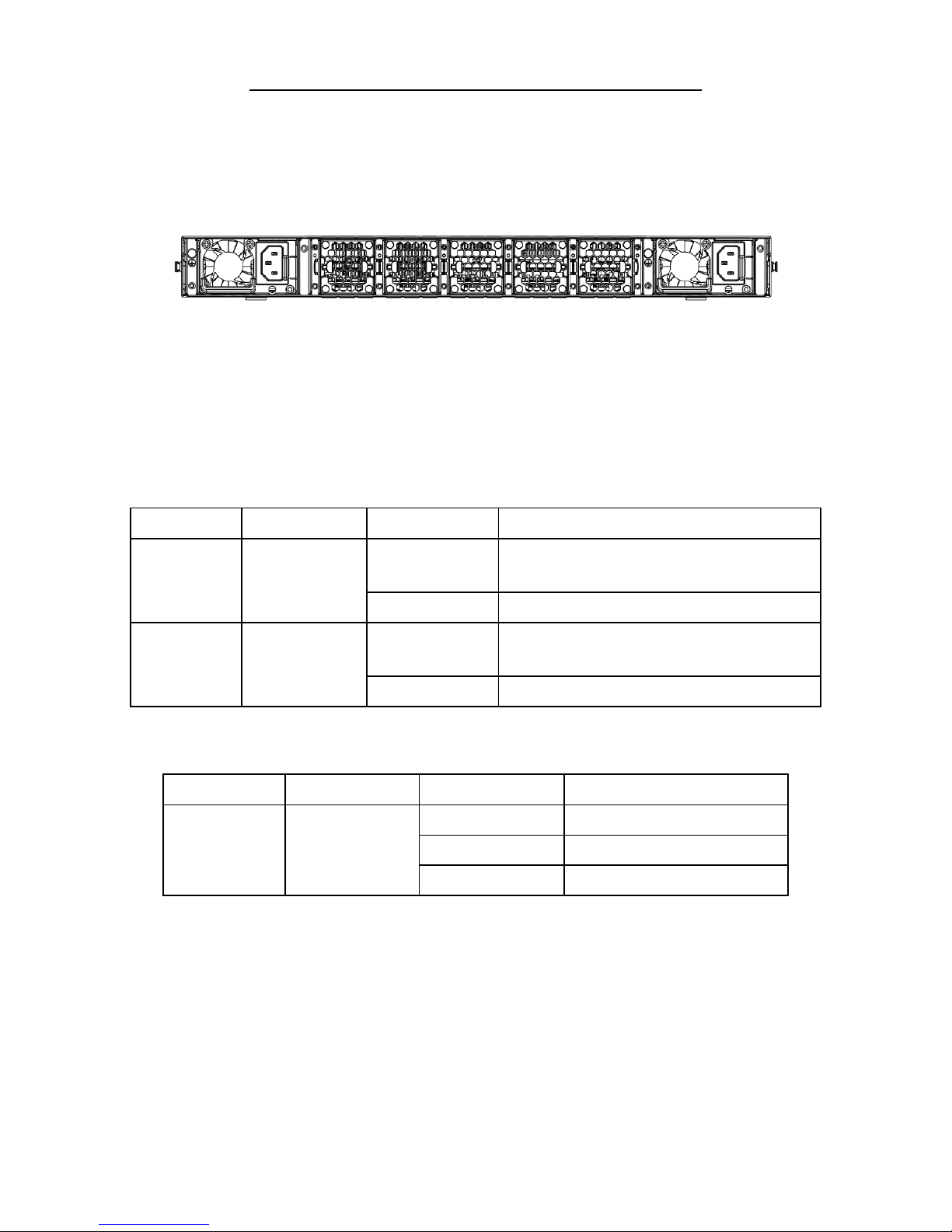
Back Panel
The back panel of the SSE-C3632S/R includes two (redundant) alternating current power modules and
five fans.
Fig 1-5. Back Panel View
1.4 Status LEDs
The front panel of the SSE-C3632S/R has 128 QSFP28 port indicator lights, two power supply indicator
lights and system automatic diagnostic LEDs. They are shown below and described in the following
tables.
Indicator Lights on the Front Panel of the SSE-C3632S/R Switches
Indicator Light
Front Panel Sign
In State
Meaning
Power supply
indicator light
P-1/P-2
Green light always
on
Power supply module is operating normally.
Out
No power supply or power fault.
System status
indicate LED
START
Green light always
on
The system is powered on and operating normally.
Out
The system is powered off.
Indicator Lights on the Rear Panel of the SSE-C3632S/R
Indicator Light
Rear Panel Sign
State
Meanings
Fan Module
Indicator Light
FAN1/FAN2/
FAN3/FAN4/ FAN5
Green light always on
Fan module is operating normally.
Red light always on
No fan module or fan speed is 0.
Out
Fan module is powered off.
Supermicro SSE-C3632S/SSE-C3632SR Switch Installation Guide
Page 10
Port Indicator Lights on the Front Panel of the SSE-C3632S/R
Indicator Light
Panel Sign
State
ETHERNET Port Link
Light (Left)
Green light wink
The port is transmitting data.
Out
There is no data transmitting on the port.
ETHERNET Port
Activity Light (Right)
Yellow light always on
The port is configured at 10Mbps/100Mbps speed
Green light always on
The port is configured at 1000Mbps speed
Out
No connection or failure to connect.
Indicator Light of
QSFP28 Port
Green light always on
The port is connecting at 100Gbps.
Amber light always on
The port is connecting at 4x25G.bps
Wink
The port is transmitting data.
Red light always on
There is a fault on the port.
Out
No connection or failure to connect.
1.5 Port Description
The SSE-C3632S/R provides 32 100Gb QSFP28 ports. Each is described below:
SSE-C3632S/R Port Description
Port mode
Specification
RJ-45 port
10/100/1000Mbps auto negotiation
MDI/MDI-X cable mode auto negotiation
QSFP28
100GBASE-CR4 transceiver, Copper, 5m
100GBASE-SR4 transceiver, 850nm, MMF, OM3/OM4, 100m
The SSE-C3632S/R provides 32 QSFP28 ports and supports use of a QSFP28 cable. It enhances the
flexibility of the network.
Supermicro SSE-C3632S/SSE-C3632SR Switch Installation Guide
Page 11
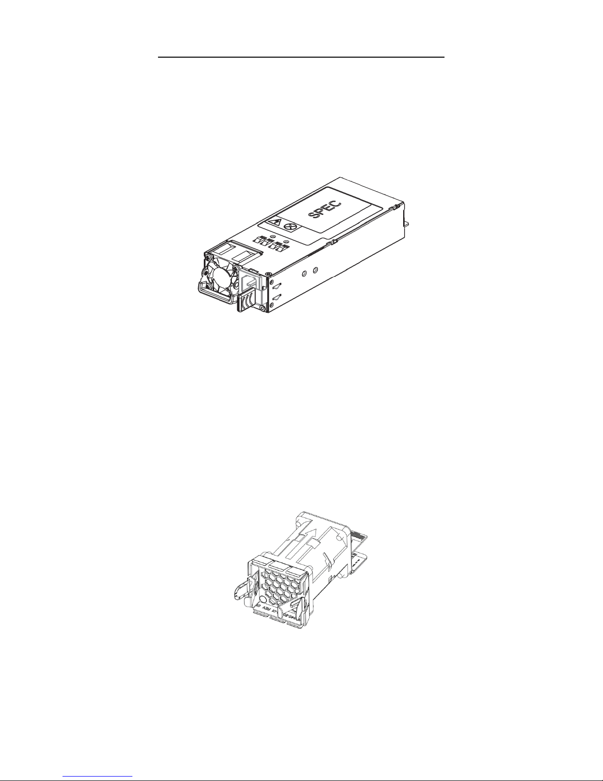
1.6 Power Supply Module
800W Power Module
The Power Supply Module (PSM) of the SSE-C3632S/R is shown in the sketch below:
Fig 1-6. Sketch of SSE-C3632S/R Power Supply Module
SSE-C3632S and SSE-C3632SR switches have two PSMs for redundancy. There are two airflow
options - front to back (SSE-C3632S) and back to front (SSE-C3632SR).
The maximum power is 800W. The input is 100VAC~240VAC and the output is 12V +/- 5%. There is a
handle for installing or removing the module on the back of the power supply. The power supply module
supports hot plug.
Caution: Different airflow power modules can not be mixed.
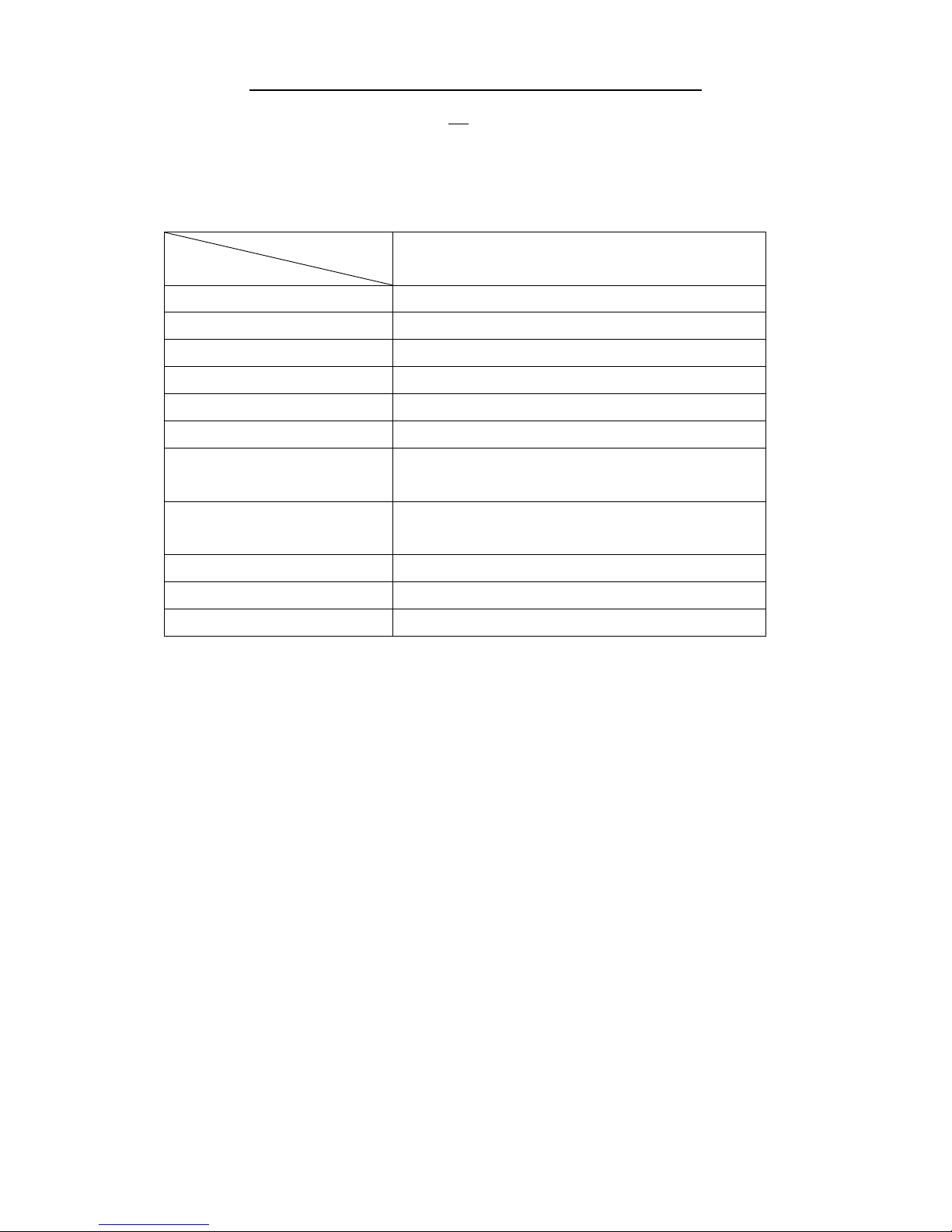
1.7 Fan Module
The fan module of the SSE-C3632S/R is shown in the sketch below:
Fig 1-7. Fan module
SSE-C3632S and SSE-C3632SR switches have 5 Fan modules in the standard configuration. The
rotation speed of the fan(s) self-adjusts to adapt to the system temperature.
Supermicro SSE-C3632S/SSE-C3632SR Switch Installation Guide
Page 12
Caution: Different airflow fan modules can not be mixed in the same switch unit. Power Supply
Modules must have the same airflow as the fan modules.
1.8 System Specifications
System Specifications of the SSE-C3632S/R
Type
Attribute
SSE-C3632S/R
Dimension(W * H * D) (mm)
433.8 * 44 * 520
Weight
10.18kg(with 2 PSU)
Fixed Port
32 QSFP28 ports
Management Port
1 RJ-45 serial console port
Power Input
100~240VAC(50~60Hz)
System Consumption
<657W
Operating Temperature
(airflow front to back)
0°C~45°C
Operating Temperature
(airflow back to front)
0°C~40°C
Storage Temperature
-40°C~75°C
Operating Relative Humidity
10%~90%, non-condensing
Storage Relative Humidity
5%~95%, non-condensing
Supermicro SSE-C3632S/SSE-C3632SR Switch Installation Guide
Page 13
Standardized Warning
Statements
2.1 About Standardized Warning Statements
The following statements are industry standard warnings, provided to warn the user of situations
which have the potential for bodily injury. Should you have questions or experience difficulty, contact
Supermicro's Technical Support department for assistance. Only certified technicians should attempt
to install or configure components.
Read this appendix in its entirety before installing or configuring components in the Supermicro
chassis
These warnings may also be found on our web site at
http://www.supermicro.com/about/policies/safety_information.cfm
Warning Definition
Warning!
This warning symbol means danger. You are in a situation that could cause bodily injury. Before you
work on any equipment, be aware of the hazards involved with electrical circuitry and be familiar with
standard practices for preventing accidents.
 Loading...