

Supermicro SSE-G2252, SSE-G2252P Installation Manual
SSE-G2252 Switch
SSE-G2252
SSE-G2252P
52-Port Layer 2 Gigabit Ethernet Switch
SSE-G2252P Switch
52-Port Layer 2 Gigabit Ethernet Switch with
48 PoE-Capable Ports
Installation Manual
Revison 1.0a
SSE-G2252/SSE-G2252P Switch Installation Manual
The information in this Installation Manual has been carefully reviewed and is believed to be accurate.
The vendor assumes no responsibility for any inaccuracies that may be contained in this document,
makes no commitment to update or to keep current the information in this manual, or to notify any person
or organization of the updates. Please Note: For the most up-to-date version of this manual, please
see our web site at www.supermicro.com.
Super Micro Computer, Inc. (“Supermicro”) reserves the right to make changes to the product described
in this manual at any time and without notice. This product, including software, if any, and document ation
may not, in whole or in part, be copied, photocop ied, re produced, translated or redu ced t o any medi um or
machine without prior written consent.
IN NO EVENT WILL SUPERMICRO BE LIABLE FOR DIRECT, INDIRECT, SPECIAL, INCIDENTAL,
SPECULATIVE OR CONSEQUENTIAL DAMAGES ARISING FROM THE USE OR INABILITY TO USE
THIS PRODUCT OR DOCUMENTATION, EVEN IF ADVISED OF THE POSSIBILITY OF SUCH
DAMAGES. IN PARTICULAR, SUPERMICRO SHALL NOT HAVE LIABILITY FOR ANY HARDWARE,
SOFTWARE, OR DATA STORED OR USED WITH THE PRODUCT, INCLUDING THE COSTS OF
REPAIRING, REPLACING, INTEGRATING, INSTALLING OR RECOVERING SUCH HARDWARE,
SOFTWARE, OR DATA.
Any disputes arising between manufacturer and cu stomer shall be governed by the laws of Santa Clara
County in the State of California, USA. The State of California, County of Santa Clara shall be the
exclusive venue for the resolution of any such disputes. Super Micro's total liabilit y for all claims will not
exceed the price paid for the hardware product.
FCC State ment: This equipment has been tested and found to comply with the limits for a Class A digi tal
device pursuant to Part 15 of the FCC Rules. These limits are designed to provide reaso nable protection
against harmful interference when the equipment is operated in a commercial environment. This
equipment generates, uses, and can radiate radio frequency energy and, if not installed and used in
accordance with the manufacturer’s instruction manual, may cause harmful interference with radio
communications. Operation of this equipment in a residential area is likely to cause harmful interference,
in which case you will be required to correct the interference at your own expense.
California Best Management Practices Regulations for Perchlorate Materials: This Perchlorate warning
applies only to products containing CR (Manganese Dioxide) Lithium coin cells. Perchlorate
Material-special handling may apply. See www.dtsc.ca.gov/hazardouswaste/perchlorate for further
details.
WARNING: HANDLING OF LEAD SOLDER MATERIALS USED IN THIS
PRODUCT MAY EXPOSE YOU TO LEAD, A CHEMICAL KNOWN TO THE
STATE OF CALIFORNIA TO CAUSE BIRTH DEFECTS AND OTHER
REPRODUCTIVE HARM.
Manual Revison 1.0a
Release Date: March 22, 2012
Unless you request and receive written permission from Super Micro Computer, Inc., you may not copy
any part of this document.
Information in this document is subject to change without notice. Other products and companies referred
to herein are trademarks or registered trademarks of their respective companies or mark holders.
Copyright © 2012 by Super Micro Computer, Inc.
All rights reserv ed .
Printed in the United States of America
ii

Preface
About this Manual
This manual is written for professional system integrators, Information Technology
professionals, service personnel, technicians and network administrators who are
responsible for installing and setting up network equipment; consequently, it assumes a
basic working knowledge of LANs (Local Area Networks). It provides information for the
installation and use of Supermicro's SSE-G2252 and SSE-G2252P switches.
Installation and maintenance should be performed by experienced professionals only.
Manual Organization
Chapter 1: Introduction
The first chapter provides a checklist of the main components included with the switches
and describes their main features.
:
Chapter 2: System Safety
You should familiarize yourself with this chapter for a general overview of safety
precautions that should be followed when installing and servicing the SSE-G2252 and
SSE-G2252P switches
Chapter 3: Network Planning
Refer here for details on network planning for the switches.
Chapter 4: Installation
This chapter describes how to install the switches.
Chapter 5: Connecting
This chapter covers how to connect the switches using network cards to PCs and
servers, as well as to other switches and hubs.
Chapter 6: Hardware Specifications
This chapter lists and describes hardware specifications for the switches.
Chapter 7: Cables
Cables and pinouts used with the SSE-G2252 and SSE-G2252P switches are
discussed in this chapter.
Chapter 8: Troubleshooting
This chapter covers troubleshooting issues for the SSE-G2252 and SSE-G2252P
switches.
iii

SSE-G2252/SSE-G2252P Switch Installation Manual
Glossary
Glossary Term Description
10BASE-T
100BASE-FX
100BASE-TX
1000BASE-LX
1000BASE-LH
1000BASE-SX
1000BASE-T
Auto-Negotiation
Bandwidth
Collision Domain Single CSMA/CD LAN segment.
IEEE 802.3 specification for 10 Mbps Ethernet over two pairs of Category
3, 4, or 5 UTP cable.
IEEE 802.3 specification for 100 Mbps Ethernet over two strands of 50/
125, 62.5/125 micron, or 9/125 micron core fiber cable.
IEEE 802.3u specification for 100 Mbps Etherne t over two pairs of
Category 5 UTP cable.
IEEE 802.3z specification for Gigabit Ethernet over two strands of 50/125,
62.5/125 or 9/125 micron core fiber cable.
Specification for long-haul Gigabit Ethernet over two strands of 9/125
micron core fiber cable.
IEEE 802.3z specification for Gigabit Ethernet over two strands of 50/125
or 62.5/125 micron core fiber cable.
IEEE 802.3ab specification for Giga bit Ether net o ver 10 0-oh m Catego ry 5,
5e or 6 twisted-pair cable (using all four wire pairs).
Signalling method allowing each node to select its optimum operati onal
mode (e.g., speed and duplex mode) based on the cap abiliti es of the node
to which it is connected.
The difference between the highest and lowest frequencies available for
network signals. Also synonymous with wire speed, the actual speed of the
data transmission along the cable.
CSMA/CD (Carrier Sense Multiple Access/Collision Detect) is the
CSMA/CD
End Station A workstation, server, or other device that does not forward traffi c.
Ethernet
Fast Ethernet
Full Duplex
Gigabit Ethernet
IEEE Institute of Electrical and Electronic Engineers.
IEEE 802.3
communication method employed by Ethernet, Fast Ethernet, and Gigabit
Ethernet.
A network communication system developed and standardized by DEC,
Intel, and Xerox, using baseband transmission, CSMA/CD access, logical
bus topology, and coaxial cable. The successor IEEE 802.3 standard
provides for integration into the OSI model and extends the physica l layer
and media with repeaters and implementations that oper ate on fiber, thin
coax and twisted-pair cable.
A 100 Mbps network communication system based on Ethernet and the
CSMA/CD access method.
Transmission method that allows two network devices to transmit and
receive concurrently, effectively doubling the bandwidth of that link.
A 1000 Mbps network communication system based on Ethernet and the
CSMA/CD access method.
Defines carrier sense multiple access with collision detection (CSMA/CD)
access method and physical layer specifications.
iv
Glossary Term Description
:
IEEE 802.3ab
IEEE 802.3u
IEEE 802.3x
IEEE 802.3z
LAN Segment Separate LAN or collision domain.
LED Light emitting diode used for monitoring a device or network condition.
Local Area Network (LAN) A group of interconnected computer and support devi ces.
Media Access Control
(MAC)
MIB
RJ-45 Connector A connect or for twisted-pair wiring.
STP Shielded Twisted Pair.
SMPS Switching Mode Power Supply.
Defines CSMA/CD access method and physical layer specifications for
1000BASE-T Gigabit Ethernet. (Now incorporated in IEEE 802.3-2005.)
Defines CSMA/CD access method and physical layer specifications for
100BASE-TX Fast Ethernet. (Now incorporated in IEEE 802.3-2005.)
Defines Ethernet frame start/stop reque st s and timers used fo r flow control
on full-duplex links. (Now incorporated in IEEE 802.3-2005.)
Defines CSMA/CD access method and physical layer specifications for
1000BASE Gigabit Ethernet. (Now incorporated in IEEE 802.3-2005.)
A portion of the networking protocol that governs access to the
transmission medium, facilitating the exchange of data between network
nodes.
An acronym for Management Information Base. It is a set of database
objects that contains information about the device.
Switched Ports Ports that are on separate collision domains or LAN segment s.
TIA Telecommunications Industry Association
UTP Unshielded twisted-pair cable.
A Virtual LAN is a collection of network nodes that share the same collision
domain regardless of their physical location or connection point in the
Virtual LAN (VLAN)
network. A VLAN serves as a logical workgroup with no physical barriers,
allowing users to share information and resources as though located on
the same LAN.
v

SSE-G2252/SSE-G2252P Switch Installation Manual
Notes
vi

Table of Contents
Chapter 1 Introduction.......................................................................1-1
1-1 Overview.............................................................................................1-1
1-2 Switch Architecture...........................................................................1-2
1-3 Network Management Options.......................................................1-2
1-4 Power-over-Ethernet.........................................................................1-2
1-5 Description of Hardware...................................................................1-3
10/100/1000BASE-T Ports......................................................................1-3
SFP Transceiver Slots ............................................................................1-3
Port and System Status LEDs.................................................................1-4
Mode Button............................................................................................1-5
Power Supply Inlet..................................................................................1-5
Grounding Point......................................................................................1-5
Reset Button...........................................................................................1-6
Console Port...........................................................................................1-6
Chapter 2 System Safety..................................................................2-1
2-1 Electrical Safety Precautions ...........................................................2-1
2-2 General Safety Precautions.............................................................2-2
2-3 Electrostatic Discharge Precautions ..............................................2-2
2-4 Operating Precautions......................................................................2-2
2-5 Compliances and Safety..................................................................2-3
FCC Class A............................................................................... ............2-3
Industry Canada - Class A................................... ... ................................2-3
CE Mark Declaration of Conformance for EMI and Safety (EEC)...........2-3
Safety Compliance..................................................................................2-4
Power Cord Safety..................................................................................2-5
France and Peru only..............................................................................2-5
2-6 Warnings and Cautionary Messages.............................................2-8
Environmental Statements......................................................................2-8
End of Product Life Sp an................................ .. ... ...................................2-9
Manufacturing Materials ...... ....................................................................2-9
Chapter 3 Network Planning..........................................................3-1
3-1 Introduction To Switching.................................................................3-1
3-2 Application Examples.......................................................................3-1
Collapsed Backbone......................... .. ... ............................... ... ... ............3-1
vii

SSE-G2252/SSE-G2252P Switch Installation Manual
PoE Connections....................................................................................3-2
Network Aggregation Plan......................................................................3-3
Remote Connections with Fiber Cable ...................................................3-4
Making VLAN Connections.....................................................................3-5
3-3 Application Notes..............................................................................3-6
Chapter 4 Installing the Switch....................................................4-1
4-1 Selecting a Site..................................................................................4-1
4-2 Ethernet Cabling................................................................................4-1
4-3 Equipment Checklist.........................................................................4-2
4-4 Optional Rack-Mounting Equipment..............................................4-2
4-5 Mounting.............................................................................................4-3
Rack Mounting........................................................................................4-3
Desktop or Shelf Mounting......................................................................4-6
4-6 Installing an Optional SFP Transceiver .........................................4-7
4-7 Connecting to a Power Source.......................................................4-8
4-8 Connecting to the Console Port......................................................4-9
Wiring Map for Serial Cable....................................................................4-9
Chapter 5 Making Network Connections...............................5-1
5-1 Connecting Network Devices..........................................................5-1
5-2 Twisted-Pair Devices........................................................................5-1
Power-over-Ethernet Connections..........................................................5-1
Cabling Guidelines.................................... ... ...........................................5-2
Connecting to PCs, Servers, Hubs, and Switches..................................5-2
Network Wiring Connections...................................................................5-3
5-3 Fiber Optic SFP Devices..................................................................5-5
5-4 Connectivity Rules ............................................................................5-6
1000BASE-T Cable Requirements.........................................................5-6
1000 Mbps Gigabit Ethernet Collision Domain.......................................5-6
100 Mbps Fast Ethernet Collision Domain..............................................5-7
10 Mbps Ethernet Collision Domain........................................................5-7
5-5 Cable Labeling and Connection Records......................................5-8
Chapter 6 Hardware Specifications...........................................6-1
6-1 Physical Characteristics...................................................................6-1
6-2 Switch Features.................................................................................6-3
6-3 Management Feat ures.....................................................................6-3
viii

Table of Contents
6-4 Standards ...........................................................................................6-3
6-5 Compliances ......................................................................................6-4
Chapter 7 Cables and Pinouts......................................................7-1
7-1 Twisted-Pair Cable Assignments....................................................7-1
10/100BASE-TX Pin Assignments..........................................................7-2
Straight-Through Wiring.................................. ................................. .......7-3
Crossover Wiring ....................................................................................7-4
1000BASE-T Pin Assignments...............................................................7-5
7-2 Cable Testing for Existing Category 5 Cable................................7-5
7-3 Adjusting Existing Category 5 Cabling to Run 1000BASE-T.....7-6
7-4 Fiber Standards.................................................................................7-6
Chapter 8 Troubleshooting.............................................................8-1
8-1 Diagnosing LED Indicators..............................................................8-1
8-2 Power and Cooling Problems..........................................................8-1
8-3 Installation ..........................................................................................8-1
8-4 In-Band Access .................................................................................8-2
ix

SSE-G2252/SSE-G2252P Switch Installation Manual
Notes
x
Chapter 1
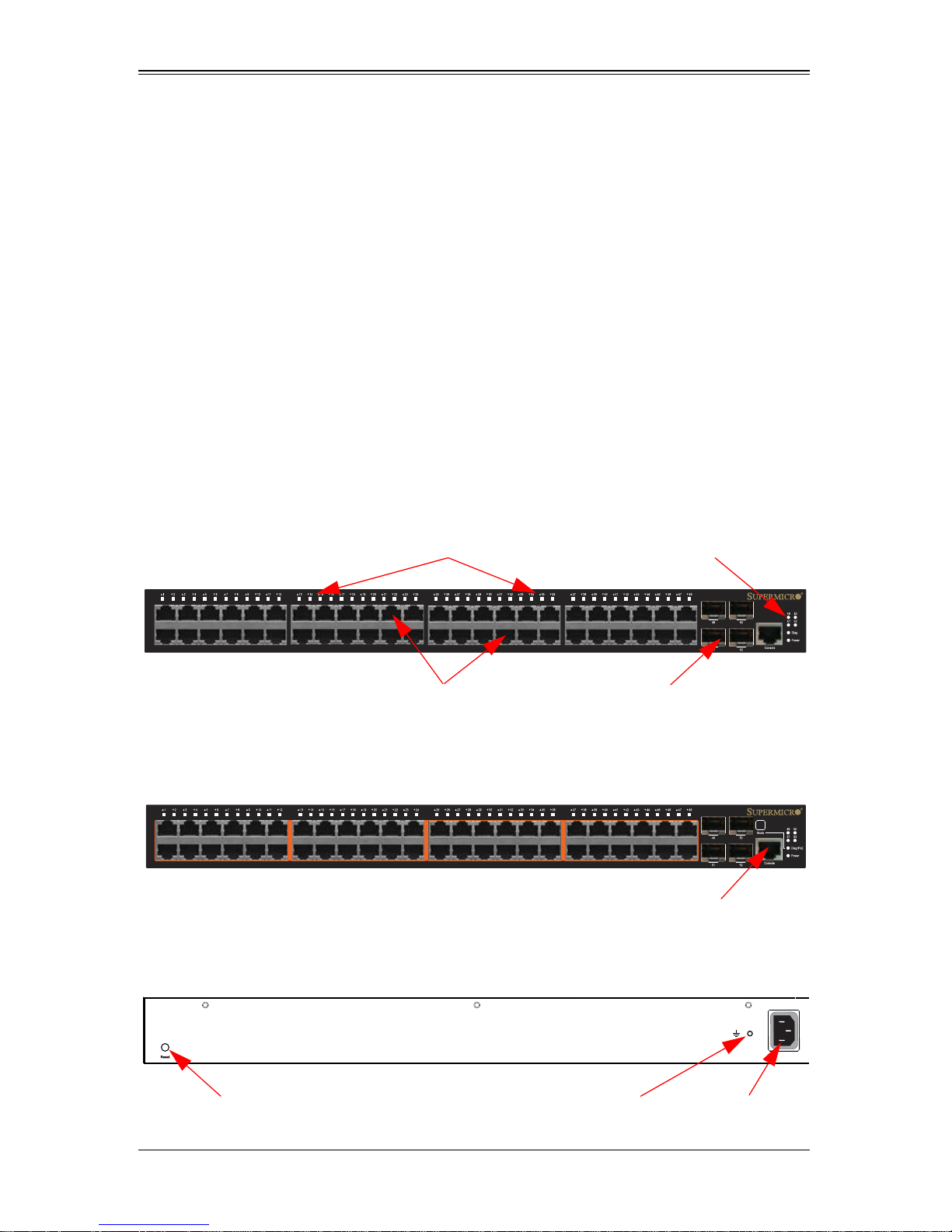
SSE-G2252
SSE-G2252P
AC 100-240V, 50-60Hz, 7A
Port Status Indicators
System Indicators
10/100/1000 Mbps RJ-45
SFP Ports
Console Port
Reset Button
Grounding Point
Power Inlet
SSE-G2252
SSE-G2252P
Rear Panel
Introduction
1-1 Overview
The SSE-G2252 and SSE-G2252P are Gigabit Ethernet Layer 2 switches with 48 10/
100/1000-BASE-T ports, and four additional SFP transceiver slots (see Figure 1-1
below). The SSE-G2252P also provides PoE power to connected devices. The switches
also include an SNMP-based management agent, which provides both in-band and
out-of-band access for managing the switch.
Both switches provide a broad range of powerful features for Layer 2 switching,
delivering reliability and consistent performance for your network traffic. They bring
order to poorly performing networks by segregating them into separate broadcast
domains with IEEE 802.1Q compliant VLANs, and empowers multimedia applications
with multicast switching and CoS services.
Figure 1-1. Front and Rear Panels
1-1

SSE-G2252/SSE-G2252P Switch Installation Manual
1-2 Switch Architecture
The switch employs a wire-speed, non-blocking switching fabric. This permits
simultaneous wire-speed transport of multiple packets at low latency on all ports. The
switch also features full-duplex capability on all ports, which effectively doubles the
bandwidth of each connection.
This switch uses store-and-forward switching to ensure maximum data integrity. With
store-and-forward switching, the entire packet must be received into a buffer and
checked for validity before being forwarded. This prevents errors from being propagated
throughout the network.
1-3 Network Management Options
With a comprehensive array of LEDs, the switch provides “at a glance” monitoring of
network and port status. The switch can be managed over the network with a web
browser or Telnet application, or via a direct connection to the console port. The switch
includes a built-in network management agent that allows it to be managed in-band
using SNMP or RMON (Groups 1, 2, 3, 9) protocols. It also has an RJ-45 serial port
(DB-9 connector) for out-of-band management. A PC may be connected to this port for
configuration and monitoring out-of-band via the supplied RJ-45 to RS232 (DB-9
connector) serial cable.
For a detailed description of the management features, refer to the Management Guide.
1-4 Power-over-Ethernet
All of the SSE-G2252P's 10/100/1000 Mbps RJ-45 ports support the IEEE 802.3at-2009
PoE standard that enables DC power to be supplied to attached devices using wires in
the connecting Ethernet cable. The total PoE power delivered by all ports cannot exceed
the 400W power budget. This means that up to eleven ports can supply a maximum
34.2W of power simultaneously to connected devices, or all 48 ports can supply up to
8.3W simultaneously.
Any PoE-compliant device attached to a port can directly draw power from the switch
over the Ethernet cable without requiring its own separate power source. This capability
gives network administrators centralized power control for devices such as IP phones
and wireless access points, which translates into greater network availability.
For each attached PoE-compliant device, the switch automatically senses the load and
dynamically supplies the required power. The switch delivers power to a device using
the wire pairs in UTP or STP cable.
1-2

Chapter 1: Introduction
1-5 Description of Hardware
Hardware descriptions are provided below.
10/100/1000BASE-T Ports
The switch contains 48 Gigabit RJ-45 ports that operate at 10 Mbps or 100 Mbp s, half or
full duplex, or at 1000 Mbps, full duplex. Because these ports support automatic MDI/
MDI-X operation, you can use straight-through cables for all network connections to
PCs or servers, or to other switches or hubs.
Each of these ports supports auto-negotiation, so the optimum transmission mode (half
or full duplex), and data rate (10, 100 or 1000 Mbps) can be selected automatically. If a
device connected to one of these ports does not support auto-negotiation, the
communication mode of that port can be configured manually.
Each port also supports IEEE 802.3x auto-negotiation of flow control, so the switch can
automatically prevent port buffers from becoming saturated.
SFP Transceiver Slots
The SFP transceiver slots on the SSE-G2252 and SSE-G2252P are not shared. These
are additional ports independent of the RJ-45 ports.
The following Table 1-1 shows a list of transceiver types which have been tested with
the switches. For an updated list of vendors supplying these transceivers, contact your
local dealer. For information on the recommended standards for fiber optic cabling, see
Section 7- 4 : "Fiber Standards" on page 7-6.
Table 1 -1. Supported SFP Transceivers
Media Standard
1000BASE-SX
1000BASE-LX
1000BASE-LH
100BASE-FX
Fiber Diameter
(microns)
50/125 850 700 m
62.5/125 850 400 m
50/125 1300 550 m
62.5/125 1300 550 m
9/125 1300 10 km
9/125 1310 35 km
50/125 or 62.5/125 1300 2 km
9/125 1300 20 km
Wavelength (nm) Maximum
Distance
1550 80 km
a
1000BASE-T
a. Maximum distance may vary for different SFP vendors.
100 m
1-3
SSE-G2252/SSE-G2252P Switch Installation Manual
SSE-G2252P
Port LEDs
System LEDs
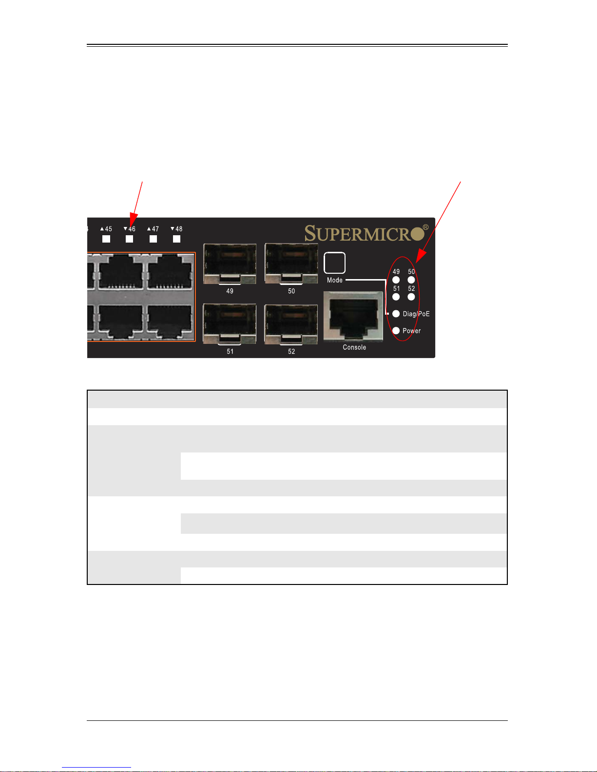
Port and System Status LEDs
The switch includes a display panel for key system and port indications that simplify
installation and network troubleshooting. The LEDs, which are located on the front panel
for easy viewing, are shown below in Figure 1-2 and described in the following Table 1-2
and Table 1-3.
Figure 1-2. Port and System LEDs
Table 1-2. Port Status LEDs
LED Condition Status
Gigabit Ethernet Ports (Ports 1-48)
On/Flashing Amber
Link/Activity/Speed
(Mode button not
depressed)
PoE Status
(Mode button is
depressed)
SFP Gigabit Ethernet Ports (Ports 49-52)
(SFP Inserted)
On/Flashing Green
Off There is no valid link on the port.
On Amber A PoE device is connected.
Off No PoE device is connected.
On Green A valid SFP transceiver is installed in the slot.
Off No SFP transceiver is installed in the slot.
Port has established a valid 10/100 Mbps network
connection. Flashing indicates activity.
Port has established a valid 1000 Mbps network
connection. Flashing indicates activity.
1-4
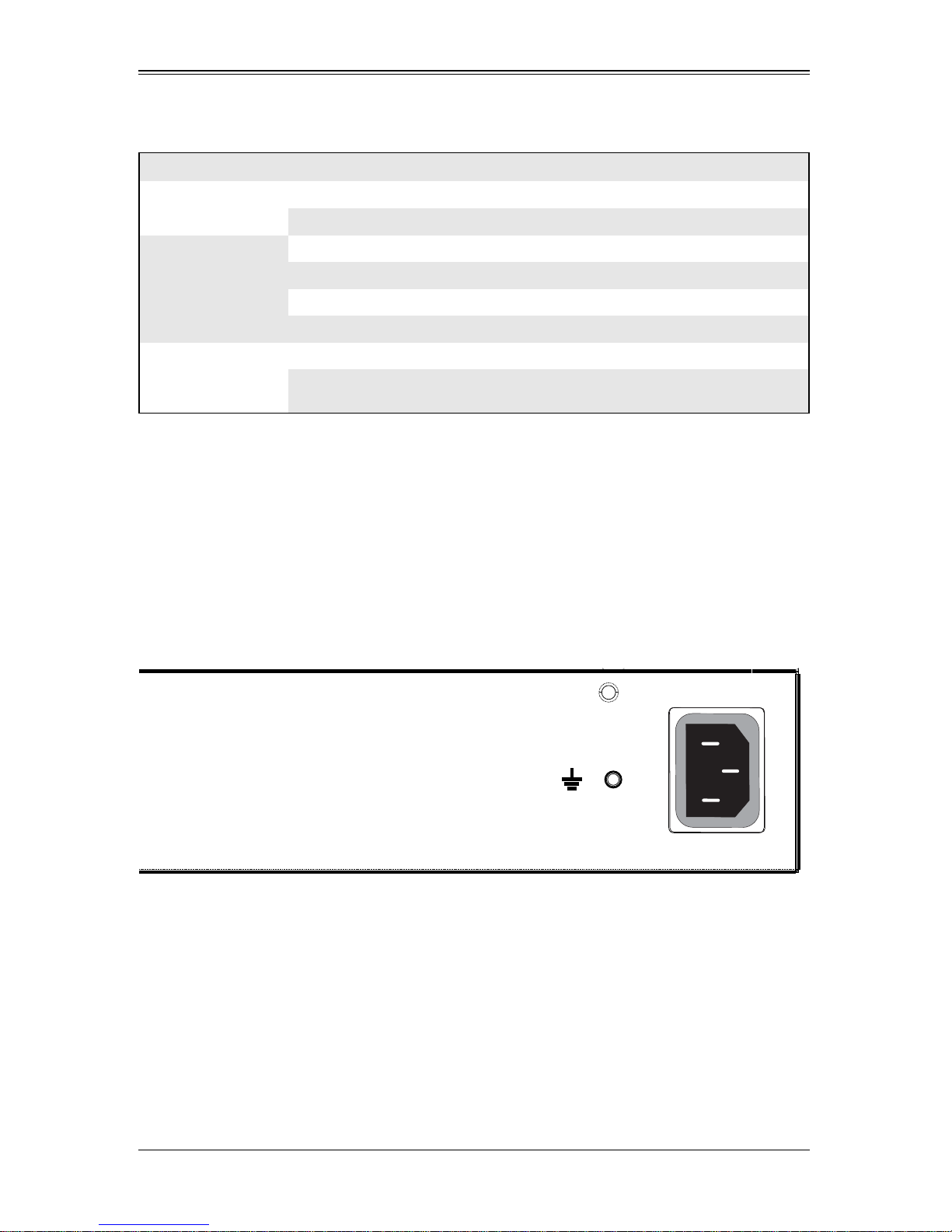
Table 1-3. System Status LEDs
AC 100-240V, 50-60Hz, 7A
LED Condition Status
Chapter 1: Introduction
Power
Diag/PoE
(Mode button not
depressed)
Diag/PoE
(Mode button
depressed)
On Green The unit’s internal power supply is operating normally.
Off The unit has no power connected.
On Green The system diagnostic test has completed successfully.
Flashing Green The system boot up is in progress.
On Amber The system diagnostic test is in progress.
Flashing Amber The system diagnostic test has detected a fault.
On Amber Port LEDs display PoE status.
Flashing Amber
Supplied PoE power has reached 95% or more of the
total system power budget.
Mode Button
When the Mode button is depressed, the port LEDs display PoE information. When the
Mode button is not depressed, the port LEDs display link and activity information.
Power Supply Inlet
There is one power inlet on the rear panel of the switch as shown in Figure 1-3. The
standard power inlet is for the AC power cord.
Figure 1-3. Power Supply Inlet
Grounding Point
To prevent accidental electrical shock or damage to your switch, it is recommended that
you ground the switch to an earth point by attaching a grounding wire (not supplied) to
the grounding point located next to the power inlet, with a metal screw. If located in a tall
building, grounding points include metal drain pipes, and other electrostatic conductive
devices that lead to the ground, or if located on the first floor of a building, the ground
outside itself.
1-5
SSE-G2252/SSE-G2252P Switch Installation Manual
SSE-G2252
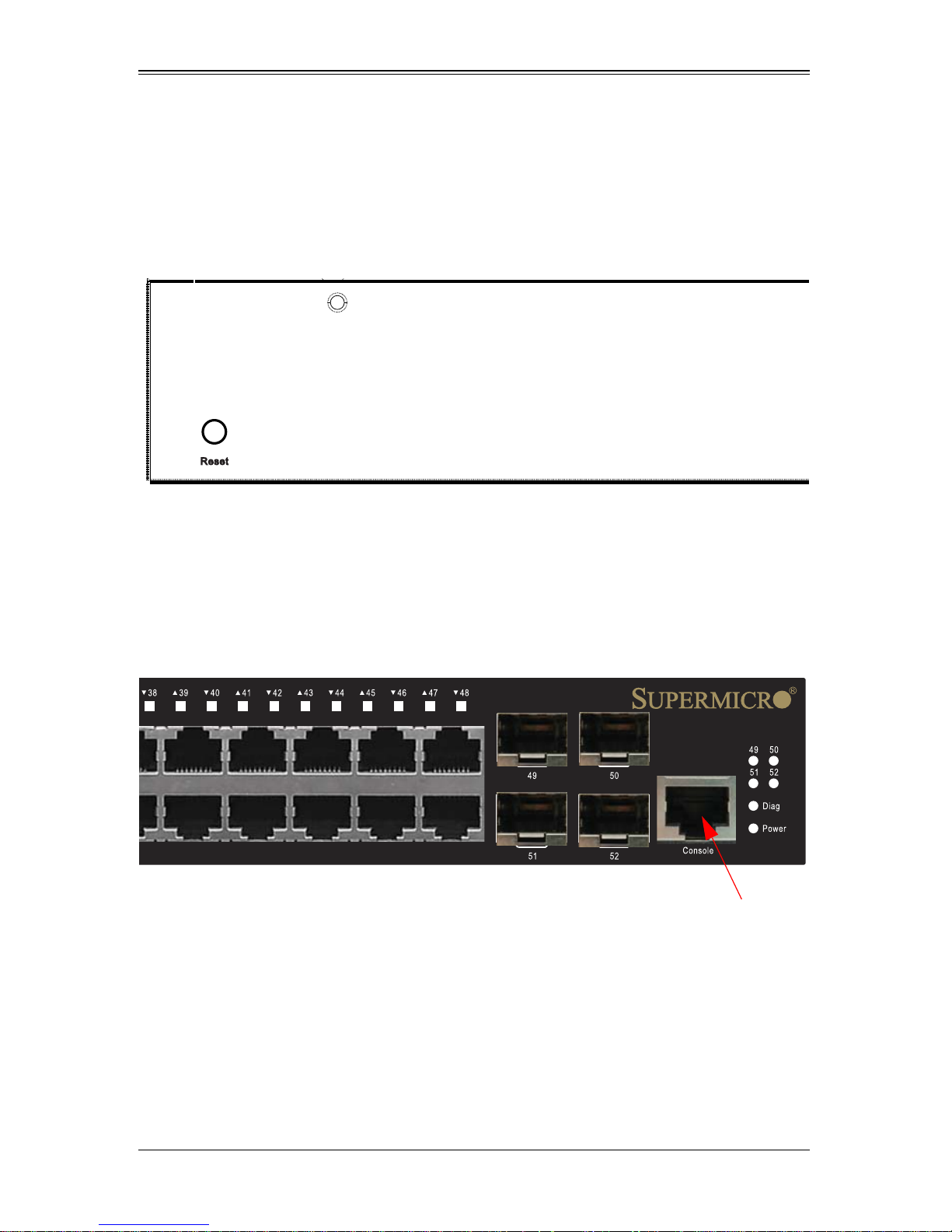
Console Port
Reset Button
If you encounter any switch malfunctions, such as a hang or non-recoverable error, you
might want to reset the switch to its default configuration by pressing and holding the
reset button for six seconds. The reset button is located on the rear panel on the
opposing side of the power inlet as shown in Figure 1-4.
Figure 1-4. Reset Button
Console Port
This port is used to connect a console device to the switch through a serial cable and is
shown in Figure 1-5. The console device can be a PC or workstation running a VT- 100
terminal emulator, or a VT-100 terminal. A crossover RJ-45 to DB-9 cable is supplied
with the unit for connecting to the console port.
Figure 1-5. Console Port
1-6

Chapter 2
System Safety
This chapter provides system safety procedures for use with both the SSE-G2252 and
SSE-G2252P switches. Please read and understand this information before installing
and using the switches.
2-1 Electrical Safety Precautions
Basic electrical safety precautions should be followed to protect yourself from harm and
the switch from damage:
• Be aware of how to power on/off the as well as the room's emergency power-off
switch, disconnection switch or electrical outlet. If an electrical accident occurs, you
can then quickly remove power from the system.
• Do not work alone when working with high voltage components.
• When working around exposed electrical circuits, another person who is familiar
with the power-off controls should be nearby to switch off the power if necessary.
• Use only one hand when working with powered-on electrical equipment. This is to
avoid making a complete circuit, which will cause electrical shock. Use extreme
caution when using metal tools, which can easily damage any electrical components
or circuit boards they come into contact with.
• Do not use mats designed to decrease electrostatic discharge as protection from
electrical shock. Instead, use rubber mats that have been specifically designed as
electrical insulators.
2-1

SSE-G2252/SSE-G2252P Switch Installation Manual
2-2 General Safety Precautions
Follow these rules to ensure general safety:
• Keep the area around the switch clean and free of clutter.
• Place the switch module cover and any system components that have been
removed away from the system or on a table so that they won't accidentally be
stepped on.
• While working on the system, do not wear loose clothing such as neckties and
unbuttoned shirt sleeves, which can come into contact with electrical circuits or be
pulled into a cooling fan.
• Remove any jewelry or metal objects from your body, which are excellent metal
conductors that can create short circuits and harm you if they come into contact with
printed circuit boards or areas where power is present.
• After accessing the inside of the system, replace the switch module's cover before
installing it back into the blade enclosure.
2-3 Electrostatic Discharge Precautions
Electrostatic discharge (ESD) is generated by two objects with different electrical
charges coming into contact with each other. An electrical discharge is created to
neutralize this difference, which can damage electronic components and printed circuit
boards.
The following measures are generally sufficient to neutralize this difference before
contact is made to protect your equipment from ESD:
• Use a grounded wrist strap designed to prevent static discharge.
• Keep all components and printed circuit boards (PCBs) in their antistatic bags until
ready for use.
• Touch a grounded metal object before removing the board from the antistatic bag.
• Do not let components or PCBs come into contact with your clothing, which may
retain a charge even if you are wearing a wrist strap.
• Handle a board by its edges only; do not touch its components, peripheral chips,
memory modules or contacts.
• When handling chips or modules, avoid touching their pins.
• Put the mainboard and peripherals back into their antistatic bags when not in use.
• For grounding purposes, make sure the blade enclosure provides excellent
conductivity between the power supplies, the blade modules and the mainboard.
2-4 Operating Precautions
Care must be taken to assure that the cover of the switch is in place when it is operating
to assure proper cooling. Out of warranty damage to the switch can occur if this practice
is not strictly followed.
2-2

Chapter 2: System Safety
2-5 Compliances and Safety
FCC Class A
This device complies with Part 15 rules. Operation is subject to the following two
conditions;
1. This device may not cause harmful interference, and
2. This device must accept any interference received, including interference that may
cause undesired operation.
This equipment has been tested and found to comply with the limits for a Class A digital
device, pursuant to part 15 of the FCC Rules. These limits are designed to provide
reasonable protection against harmful interference when the equipment is operated in a
commercial environment. This equipment generates, uses, and can radiate radio
frequency energy and, if not installed and used in accordance with the instruction
manual, may cause harmful interference to radio communications. Operation of this
equipment in a residential area is likely to cause harmful interference in which case the
user will be required to correct the interference at his own expense.
You are cautioned that changes or modifications not expressly approved by the party
responsible for compliance could void your authority to operate the equipment.
Y ou may use unshielded twisted-pair (UTP) for RJ-45 connections - Category 3 or better
for 10 Mbps connections, Category 5 or better for 100 Mbps connections, Category 5,
5e, or 6 for 1000 Mbps connections. For fiber optic connections, you may use 50/125 or
62.5/125 micron multimode fiber or 9/125 micron single-mode fiber.
Industry Canada - Class A
This digital apparatus does not exceed the Class A limits for radio noise emissions from
digital apparatus as set out in the interference-causing equipment standard entitled
“Digital Apparatus,” ICES-003 of the Department of Communications.
Cet appareil numérique respecte les limites de bruits radioélectriques applicables aux
appareils numériques de Classe A prescrites dans la norme sur le matériel brouilleur:
“Appareils Numériques,” NMB-003 édictée par le ministère des Communications.
CE Mark Declaration of Conformance for EMI and Safety
(EEC)
This information technology equipment complies with the requirements of the Council
Directive 2004/108/EC on the Approximation of the laws of the Member States relating
to Electromagnetic Compatibility and 2006/95/EC for electrical equipment used within
certain voltage limits and the Amendment Directive 93/68/EEC. For the evaluation of the
compliance with these Directives, the following standards were applied to the
SSE-G2252 and SSE-G2252P switches.
2-3

SSE-G2252/SSE-G2252P Switch Installation Manual
Limited class A according to EN 55022:2010
RFI Emission:
Immunity:
Limited class A for harmonic current emission according to EN 61000-3-2/2006
Limitation of voltage fluctuation and flicker in low- voltage supply system
according to EN 61000-3-3/ 2008
Product family standard according to EN 55024:2010
Electrostatic Discharge according to
EN 61000-4-2:2008
(Contact Discharge: ±4 kV, Air discharge: ±8 kV)
Radio-frequency electromagnetic field according to EN 61000-4-3:2010
(80 – 1000 MHz with 1 kHz AM 80% Modulation:
3 V/m)
Electrical fast transient/burst according to
EN 61000- 4-4:2004
(AC/DC power supply: ±1 kV, Data/Signal lines:
±5 kV)
Surge immunity test according to
EN 61000-4-5:2005
(AC/DC Line to Line: ±1 kV, AC/DC Line to Earth: ±2 kV)
Immunity to conducted disturbances, Ind uced by radi o-frequency field:
EN61000-4-6:2008
(0.15 – 80 MHz with 1 kHz AM 80% Modulation:
3 V/m)
Power frequency magnetic field immunity test according to EN 61000-4-8:2009
(1 A/m at frequency 50 Hz)
Volt age dips, short interruptions and voltage variations immunity test according
to
EN 61000-4- 11:2004
(>95% Reduction @10 ms, 30% Reduction @500 ms, >95% Reduction @5000
ms)
LVD: EN 60950-1:2006
Safety Compliance
This product complies with and conforms to the following international Product Safety
standards as applicable:
• Safety of Information Technology Equipment, IEC(EN) 60950-1, including all
relevant national deviations as listed in Compliance with IEC for Electrical
Equipment (IECEE)
• Safety of Information Technology Equipment, CAN/CSA-C22.2 No. 60950-1/UL
60950-1
2-4
 Loading...