

Supermicro SC942i-550, SC942i-600, SC942S-600 Installation Manual
1.0
®
SUPER
SC942 CHASSIS
INSTALLATION GUIDE
SC942S-600 SC942i-600/550

SUPER SC942 Chassis User's Guide
1-2
Table of Contents
Chapter I: Unpacking and Check Lists ....................................1-3
Chapter 2: Installation Procedures ...........................................2-1
Section 1: Installing components into the SC942 Chassis............. 2-1
A. Removing the Side Cover of the SC942 Chassis ................................ 2-1
B. Removing the SCSI Drive Trays .............................................................. 2-2
C. Removing the Rear Exhaust Fan and Installing the Motherboard ..... 2-3
D. Removing the Components from and Installing Devices into the 5.25"
Drive Bays........................................................................................................ 2-4
E. Installing the Rear Chassis Lock ............................................................. 2-5
F. Removing the Front Side Cover to Access the Drives ....................... 2-7
Section 2: Installing the SC942 as a Rackmount ............................. 2-9
G. Rackmount Rail Kit-CSE-PT26 .................................................................. 2-9
H. Removing the Top Chassis Cover and Chassis Feet to install Chassis
for Rackmount purpose................................................................................ 2-10
I. Attaching Chassis Ears to the Chassis ............................................... 2-11
J. Installing Chassis Rails .......................................................................... 2-12
K. Rack Installation ....................................................................................... 2-13
Appendix A: CSE-M35S/CSE-M35T1 Mobile Rack ................. A-1
A. Packaging List ........................................................................................... A - 2
B. Technical Specifications .......................................................................... A-2
Appendix B: Power Supply Specifications ............................ B-1
Appendix C: SCSI (Super) GEM Driver Installation Instructions
for Windows OS ........................................................................... C-1
1-3
Chapter 1: Unpacking and Check Lists
Chapter 1- Unpacking and Check Lists
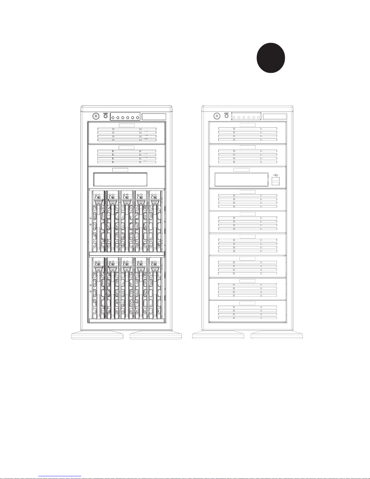
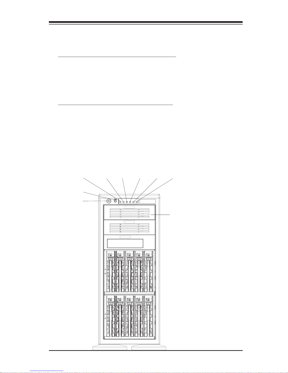
1-A. The SC942S-600 chassis
The SC942S chassis contains the following:
One (1) 5.25" drive bay (for floppy drive)
Two (2) 5.25" drive bays (for peripheral drives)
Ten (10) SCA 1" drive trays
Three (3) Hot-swappable 120mm chassis fans
One (1) 120mm rear exhaust fan
The accessory box contains the following:
One set of motherboard screws
One set of drive screws
One set of HDD (hard disk drive) screws
One (1) chassis lock mechanism
Three (3) AC power cords
Power Button
Reset Button
5.25" Expansion Bays
(SC942S-600)
PWR On
One (1) 30" SCSI cable (CBL-028)
One (1) 10" SCSI cable (CBL-043)
HDD Activity
OH
PWR Fail LAN1
LAN2

SUPER SC942 Chassis User's Guide
1-4
1-B. The SC942i chassis
The SC942i chassis contains the following:
Eight (8) 5.25" peripheral drive bays
One (1) 5.25" drive bay for floppy drive
Three (3) Hot-swappable120mm chassis fans (*SC 942i-600)
Two (2) Hot-swappable120mm chassis fans (*SC 942i-550)
One (1) 120mm Rear Exhaust fan
Two (2) Front accessible USB 2.0 ports
The accessory box contains the following:
One set of motherboard screws
One set of drive screws
One set of HDD (hard disk drive) screws
One (1) chassis lock mechanism
One (1) AC power cord(*SC 942i-550)
Power Button
Reset Button
USB 2.0 Ports (*SC 942i only)
(SC942i-600/550)
5.25" Expansion Bays
Three (3) AC power cords(*SC 942i-600)
PWR On
HDD Act OH PWR Fail LAN1
LAN2
2-1
Chapter 2: Installation Procedures
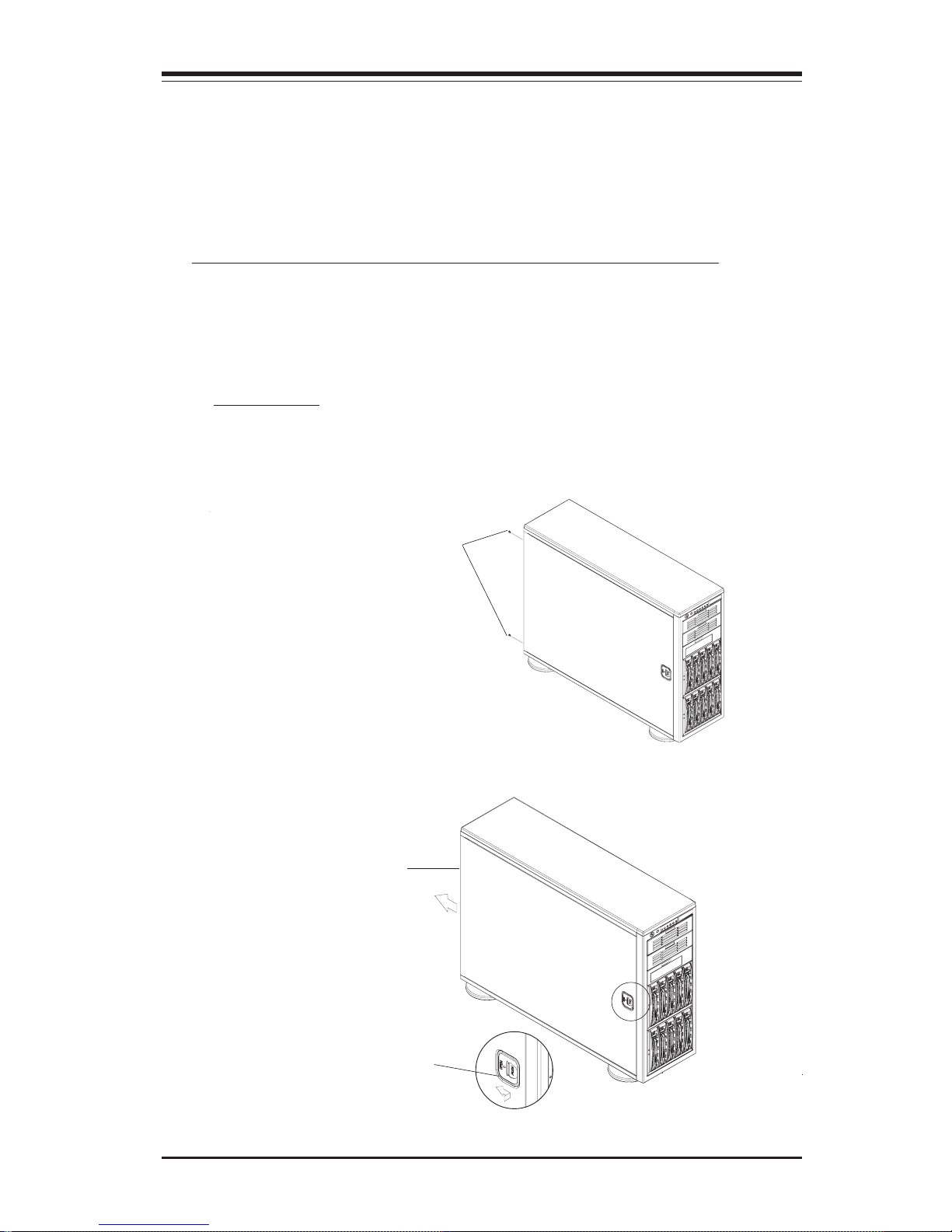
A. Removing the Side Cover of the SC942 Chassis
Before installing any components, replacing chassis fans or accessing the
motherboard, you will first need to remove the side cover.
Procedures
1. Remove the two screws from the back lip of the side cover (-this is the
left cover when you looking from the front.)
3. You can now lift the side cover up and off the chassis.
2. Push in the release tab on the cover and push the cover back to the rear
of the chassis about 1/2 inch.
Remove the screws
Push in the Release Tab
Push the cover toward
the rear of the chassis
Chapter 2: Installation Procedures
Section 1: Installing Components into the SC942
Chassis
SUPER SC942 Chassis User's Guide
2-2
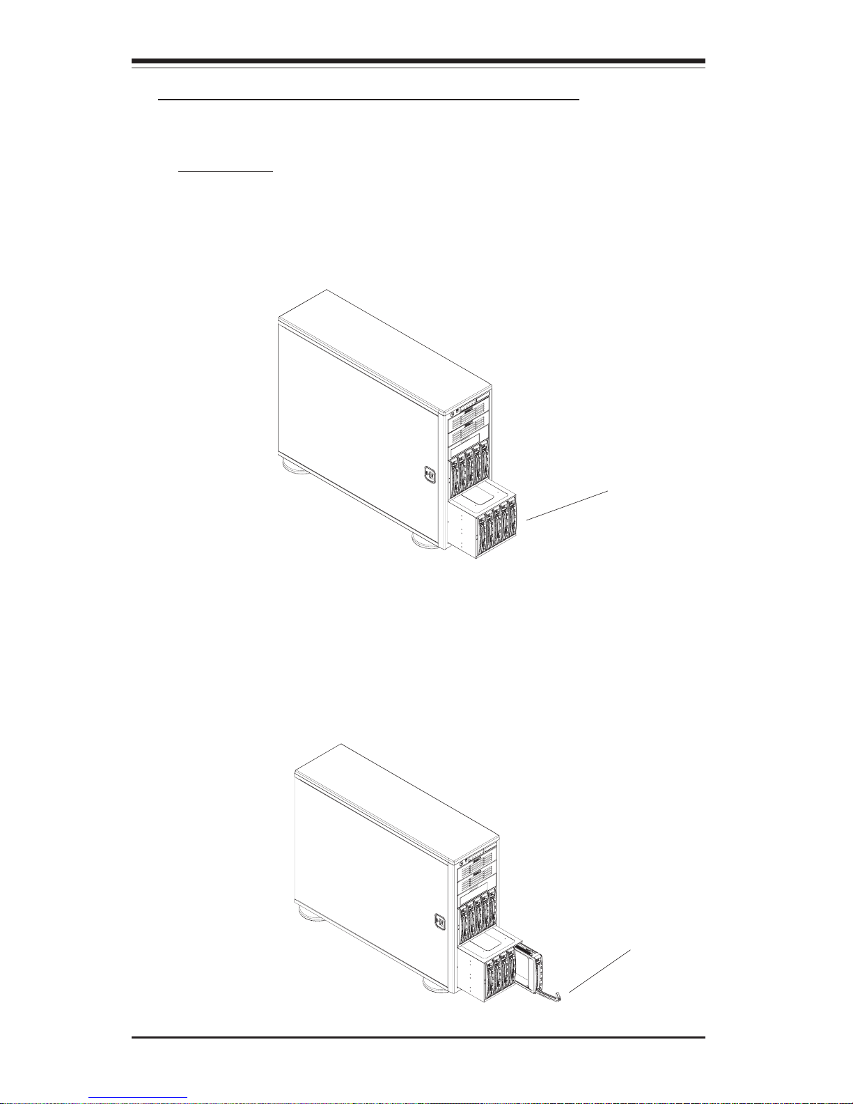
B. Removing the SCSI Drive Trays (*SC942S)
Procedures
1.Pull out the SCSI Drive Trays located on the front side of the
chassis(*SC942S only)
2. Pull the SCSI Drive Bay outwards, and press the release tab located on
the SCSI Drive Bay. Then, you can access the SCSI Drive.
Pull the SCSI Drive
Trays outwards
Press the release tab
and open the drive bay
door
2-3
Chapter 2: Installation Procedures
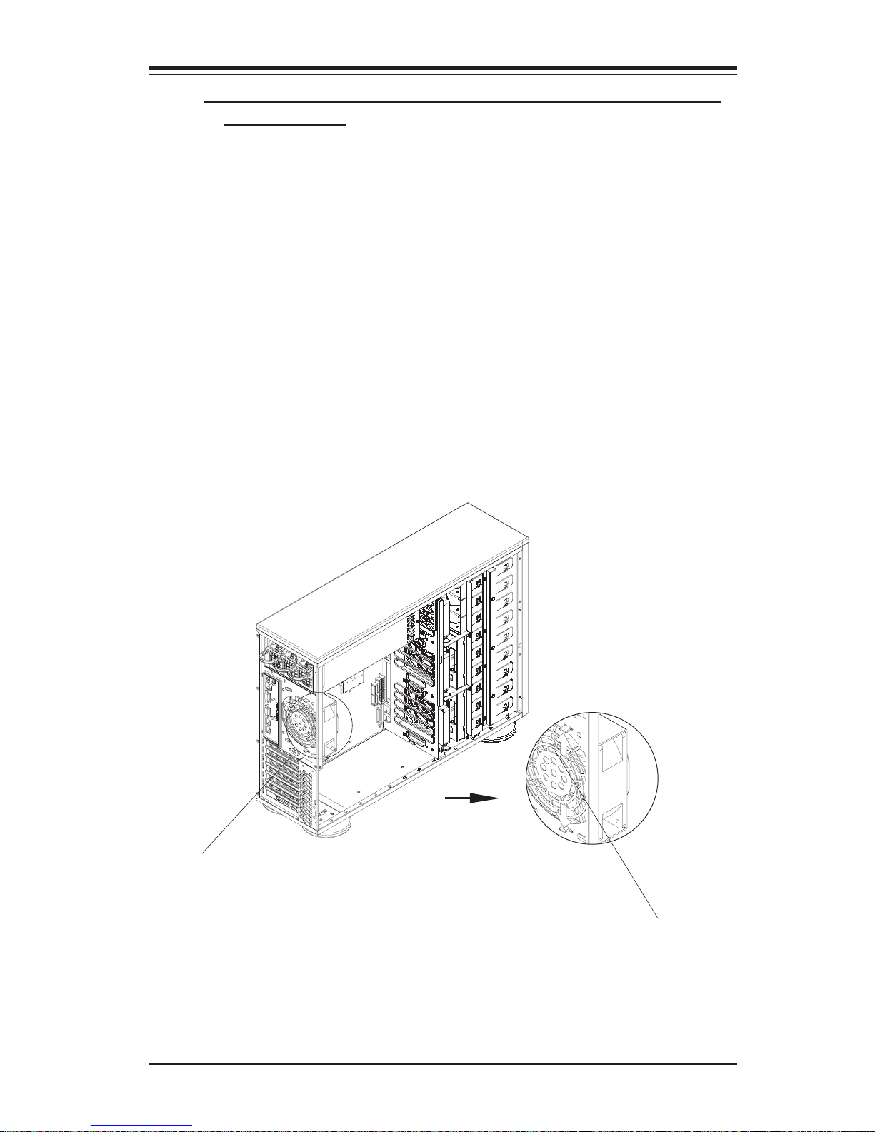
C. Removing the Rear Exhaust Fan and Installing the
Motherboard
(You will need to remove the rear exhaust fan before you install the
motherboard.)
Procedures
1. Remove the side cover from the chassis (refer to Section A).
2. Locate the exhaust fan tabs on the back panel (See picture below right.)
3. Apply pressure to the tabs (located on the top and the bottom of the rear
exhaust fan) to snap the fan out of its locked position.
4. Pull the fan away from the chassis.
Rear Exhaust Fan
Apply Pressure to the
tabs to loosen the fan,
and then, pull the fan
out from the chassis.
SUPER SC942 Chassis User's Guide
2-4
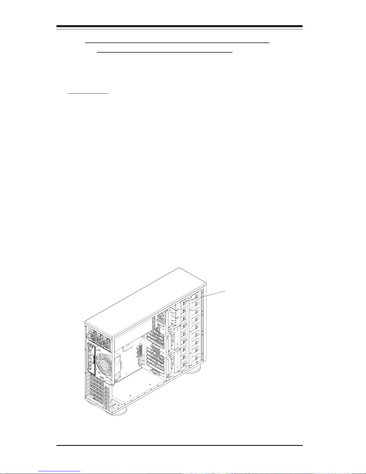
D. Removing Components from and Installing
Devices into the 5.25" Drive Bays
After removing the side cover from the chassis, you can remove or install
devices into the drive bays (See Section A for removing the side cover).
Procedures
1. Remove the side cover to access the 5.25" drive bays.
2. Remove the screws of the bay you wish to install or remove a component from. (*The chassis comes with dummy modules in all bays to maintain
adequate airflow. These dummy modules should remain in the chassis until
you want to add a component. Note that the top two bays are combined into
a single module. To add components, you must first remove the four screws
corresponding both bays.)
3. After removing the screws, push the drive module out from the front of
the chassis. For the floppy drive bay, you must first remove the two face
plates.
4. Attach the dummy rails to the new drive and insert the new drive into the
bay. Secure it to the chassis with the screws you've removed. Remember
to plug the data and power cables into the drive. When finished, place the
chassis side cover to its place and secure it with the screws.
Remove the screws
2-5
Chapter 2: Installation Procedures
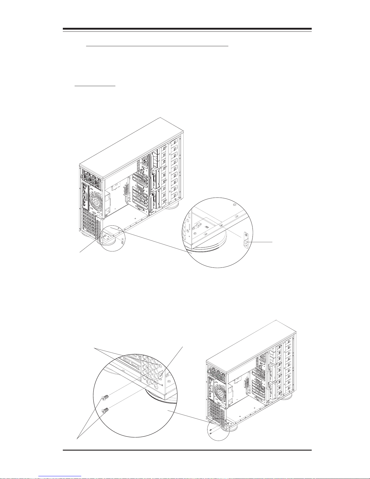
E. Installing the Rear Chassis Lock
Follow the procedures listed below to install the Rear Chassis Lock.
Procedures
1. Locate the hole at the right bottom corner of the rear side of the chassis.
Also locate the lock bracket included in your shipping package.
Hole for the lock bracket
2. Insert the lock bracket into the hole (*See above) and secure the lock
bracket onto the chassis by putting flat screws on holes on the top and
bottom of the lock bracket hole as shown below:
Holes for the screws
lock bracket
screws
lock bracket
SUPER SC942 Chassis User's Guide
2-6
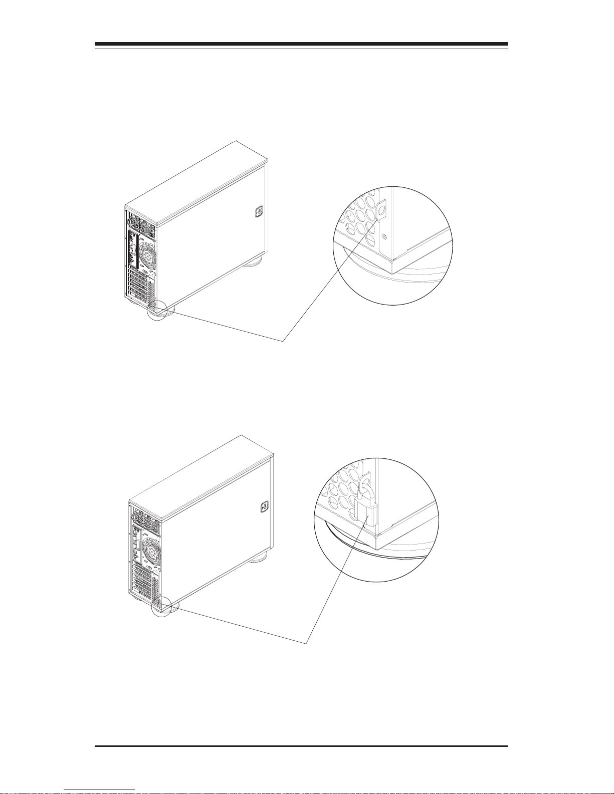
3. Slide the side cover back to the proper position. Make sure that the lock
bracket is easily accessible from the rear of the chassis.
Lock Bracket
4. Secure the system by putting a lock(*not included) on the lock bracket as
shown below:
Lock (*Not included)
 Loading...