

Supermicro SBI-7125W-S6, SBI-7125B-T1 User Manual
SBI-7125W-S6
Blade Module
User’s Manual
Revison 1.0
SBI-7125W-S6 Blade Module User’s Manual
The information in this User’s Manual has been carefully reviewed and i s believed to be accurate. The
vendor assumes no responsibility for any inaccuracies that may be contained in this document, makes no
commitment to update or to keep current the information in this manual, or to not ify any person or
organization of the u pdates. Plea se Note: For the most up-to-date version of this manual, please see
our web site at www.supermicro.com.
Super Micro Computer, Inc. (“Supermicro”) reserves the right to make changes to the product described
in this manual at any time and without notice. This product, including software, if any, and documentation
may not, in whole or in part, be copied, photocop ied, re produced, translated or redu ced t o any medi um or
machine without prior written consent.
IN NO EVENT WILL SUPERMICRO BE LIABLE FOR DIRECT, INDIRECT, SPECIAL, INCIDENTAL,
SPECULATIVE OR CONSEQUENTIAL DAMAGES ARISING FROM THE USE OR INABILITY TO USE
THIS PRODUCT OR DOCUMENTATION, EVEN IF ADVISED OF THE POSSIBILITY OF SUCH
DAMAGES. IN PARTICULAR, SUPERMICRO SHALL NOT HAVE LIABILITY FOR ANY HARDWARE,
SOFTWARE, OR DATA STORED OR USED WITH THE PRODUCT, INCLUDING THE COSTS OF
REPAIRING, REPLACING, INTEGRATING, INSTALLING OR RECOVERING SUCH HARDWARE,
SOFTWARE, OR DATA.
Any disputes arising between manufacturer and cu stomer shall be governed by the laws of Santa Clara
County in the State of California, USA. The State of California, Co unty of Santa Clara shall be the
exclusive venue for the resolution of any such disputes. Super Micro's total liabilit y for all claims will not
exceed the price paid for the hardware product.
FCC State ment: This equipment has been tested and found to comply with the limits for a Class A digital
device pursuant to Part 15 of the FCC Rules. These limits are designed to provide reasonable protection
against harmful interference when the equipment is operated in a commercial environment. This
equipment generates, uses, and can radiate radio frequency energy and, if not installed and used in
accordance with the manufacturer’s instruction manual, may cause harmful interference with radio
communications. Operation of this equipment in a residential area is likely to cause harmful interference,
in which case you will be required to correct the interference at your own expense.
California Best Management Practices Regulations for Perchlorate Materials: This Perchlorate warning
applies only to products containing CR (Manganese Dioxide) Lithium coin cells. Perchlorate
Material-special handling may apply. See www.dtsc.ca.gov/hazardouswaste/perchlorate for further
details.
WARNING: HANDLING OF LEAD SOLDER MATERIALS USED IN THIS
PRODUCT MAY EXPOSE YOU TO LEAD, A CHEMICAL KNOWN TO THE
STATE OF CALIFORNIA TO CAUSE BIRTH DEFECTS AND OTHER
REPRODUCTIVE HARM.
Manual Revison 1.0
Release Date: February 18, 2009
Unless you request and receive written permission from Super Micro Computer, Inc., you may not copy
any part of this document.
Information in this document is subject to change without notice. Other products and companies referred
to herein are trademarks or registered trademarks of their respective companies or mark holders.
Copyright © 2009 by Super Micro Computer, Inc.
All rights reserv ed .
Printed in the United States of America
ii

Preface
About this Manual
This manual is written for professional system integrators, Information Technology
professionals, service personnel and technicians. It provides information for the
installation and use of Supermicro's SBI-7125W-S6 Blade Module. Installation and
maintenance should be performed by experienced professionals only.
Manual Organization
Chapter 1: Introduction
The first chapter provides a checklist of the main components included with the
SBI-7125W-S6 Blade Module and describes its main features.
Chapter 2: System Safety
You should familiarize yourself with this chapter for a general overview of safety
precautions that should be followed when installing and servicing the SBI-7125W-S6
Blade Module.
Chapter 3: Setup and Installation
Refer to this chapter for details on installing the SBI-7125W-S6 Blade Module into the
SuperBladeSuperBlade chassis. Other sections cover the installation and placement of
memory modules and the installation of hard disk drives into the blade module.
Chapter 4: Blade Module Features
This chapter coves features and component information about the SBI-7125W-S6 Blade
Module. Included here are descriptions and information for mainboard components,
connectors, LEDs and other features of the blade module.
Chapter 5: RAID Setup Procedure
RAID setup and operations for the SBI-7125W-S6 Blade Module are covered in this
chapter.
Chapter 6: BIOS
BIOS setup is covered in this chapter for the SBI-7125W-S6 Blade Module.
Appendix A: BIOS POST Codes
BIOS POST Codes for the SBI-7125W-S6 Blade Module are explained in this appendix.
Appendix B: iSCSI Setup Procedure
The iSCSI setup procedure for the blade module is described in this appendix.
iii

SBI-7125W-S6 Blade Module User’s Manual
Notes
iv

Table of Contents
Chapter 1 Introduction.......................................................................1-1
1-1 Overview.............................................................................................1-1
1-2 Product Checklist of Typical Components.....................................1-1
1-3 Blade Module Features....................................................................1-2
Processors..............................................................................................1-2
Memory...................................................................................................1-2
Storage....................................................................................................1-3
Density....................................................................................................1-3
1-4 Contacting Supermicro.....................................................................1-4
Chapter 2 System Safety..................................................................2-1
2-1 Electrical Safety Precautions ...........................................................2-1
2-2 General Safety Precautions.............................................................2-2
2-3 Electrostatic Discharge Precautions..............................................2-2
2-4 Operating Precautions......................................................................2-2
Chapter 3 Setup and Installation.................................................3-1
3-1 Overview.............................................................................................3-1
3-2 Installing Blade Modules..................................................................3-1
Powering Up a Blade Unit.......................................................................3-1
Powering Down a Blade Unit ..................................................................3-1
Removing a Blade Unit from the Enclosure............................................3-1
Removing/Replacing th e Bl ade Cover....................................................3-2
Installing a Blade Unit into the Enclosure ...............................................3-2
3-3 Processor Installation .......................................................................3-4
3-4 Onboard Battery Installation............................................................3-5
3-5 Memory Installation...........................................................................3-6
Populating Memory Slots........................................................................3-6
DIMM Installation....................................................................................3-7
3-6 Hard Disk Drive Installation.............................................................3-8
3-7 Installing the Operating System....................................................3-10
Installing with an External USB CD-ROM Drive....................................3-10
Installing via PXE Boot..........................................................................3-10
Installing via Virtual Media (Drive Redirection) .....................................3-11
3-8 Management Software ...................................................................3-11
v

SBI-7125W-S6 Blade Module User’s Manual
3-9 Configuring and Setting up RAID.................................................3-11
Chapter 4 Blade Module Features..............................................4-1
4-1 Control Panel.....................................................................................4-2
Power Button ..........................................................................................4-3
KVM Button.............................................................................................4-3
LED Indicators ........................................................................................4-3
KVM Connector.......................................................................................4-3
4-2 Mainboard...........................................................................................4-4
Jumpers..................................................................................................4-6
CMOS Clear............................................................................................4-6
4-3 Blade Unit Components...................................................................4-6
Memory Support .....................................................................................4-7
Hard Disk Drives.....................................................................................4-7
Chapter 5 RAID Setup Procedure...............................................5-1
5-1 MegaRAID Storage Manager Software Overview.......................5-1
Creating Storage Configurations.............................................................5-1
Monitoring Storage Devices....................................................................5-1
Maintaining Storage Configurations........................................................5-2
Hardware and Software Requirements...................................................5-2
5-2 MegaRAID Storage Manager Software Insta llation.....................5-2
Installing MegaRAID Storage Manager for Microsoft Windows..............5-2
Installing MegaRAID Storage Manager for Linux....................................5-5
Linux Error Messages..........................................................................5-6
5-3 MegaRAID Storage Manager Window and Menus......................5-7
Starting MegaRAID Storage Manager Software .....................................5-7
MegaRAID Storage Manager Window....................................................5-9
Physical/Logical View Panel ................................................................5-9
Properties/Operations/Graphical View Panel.....................................5-10
Event Log Panel................. ... .......................................... ...................5-10
Menu Bar............................................................................................5-10
5-4 Configuration....................................................................................5-12
Creating a New Storage Configuration .................................................5-12
Understanding Virtual Disk Parameters.............................................5-13
Using Auto Configuration............................... ....................................5-14
Using Guided Configuration...............................................................5-15
Using Manual Confi guration: RAID 0 ................................................5-17
Using Manual Configuration: RAID 1 .................................................5-19
vi

Using Manual Configuration: RAID 5 .................................................5-20
Using Manual Confi guration: RAID 10 ..............................................5-21
Using Manual Confi guration: RAID 50 ..............................................5-22
Adding Hotspare Disks..........................................................................5-23
Changing Adjustable Task Rates..........................................................5-23
Changing Virtual Disk Properties..........................................................5-24
Deleting a Virtual Disk...........................................................................5-24
Saving a Storage Configur at ion to Disk................................................5-25
Clearing a Storage Configuration from a Controller..............................5-25
Adding a Saved Storage Configuration.................................................5-25
Chapter 6 BIOS.......................................................................................6-1
6-1 Introduction.........................................................................................6-1
System BIOS ..........................................................................................6-1
How To Change the Configuration Data .................................................6-1
Starting the Setup Utility........... ... ............................................................6-1
6-2 BIOS Updates....................................................................................6-2
Flashing BIOS.........................................................................................6-2
6-3 Running Setup...................................................................................6-3
6-4 Main BIOS Setup...............................................................................6-4
6-5 Advanced Setup................................................................................6-5
6-6 Security.............................................................................................6-12
6-7 Boot...................................................................................................6-13
Boot Priority Order/Excluded from Boot Order......................................6-13
6-8 Exit.....................................................................................................6-13
Appendix A BIOS POST Codes....................................................A-1
A-1 BIOS POST Messages....................................................................A-1
A-2 BIOS POST Codes...........................................................................A-3
Recoverable POST Errors............................................ ..........................A-4
Terminal POST Errors.............. .......................................... ... ..................A-4
Appendix B iSCSI Setup Procedure..........................................B-1
vii

SBI-7125W-S6 Blade Module User’s Manual
Notes
viii

List of Figures
Figure 1-1. Full Rack of Blade Enclosures and Blade Servers.........................1-3
Figure 3-1. Inserting a Blade into the Enclosure...............................................3-3
Figure 3-2. Locking the Blade into Position.......................................................3-3
Figure 3-3. Installing a Processor in a Socket...................................................3-5
Figure 3-4. Installing the Onboard Battery.................. ... ... ................................3-6
Figure 3-5. 8-slot DIMM Numbering..................................................................3-7
Figure 3-6. Installing a DIMM into a Memory Slot........................... ..................3-8
Figure 3-7. Installing a Hard Drive in a Carrier..................................................3-9
Figure 4-1. SBI-7125W-S6 Blade Unit Front View............................................4-1
Figure 4-2. Blade Control Panel........................................................................4-2
Figure 4-3. B7DW3 Mainboard .........................................................................4-4
Figure 4-4. Intel 5400 MCH/ESB2 Chipset: Block Diagram..............................4-5
Figure 4-5. Exploded View of SBI-7125W-S6 Blade Module............................4-6
Figure 5-1. Customer Information Screen.........................................................5-3
Figure 5-2. Setup Type Screen.........................................................................5-4
Figure 5-3. Select Server Window ....................................................................5-7
Figure 5-4. Server Login Window......................................................................5-8
Figure 5-5. MegaRAID Storage Manager Window............................................5-9
Figure 5-6. Configuration Wizard Mode Selection Screen..............................5-12
Figure 5-7. Auto Configuration Screen............................................................5-14
Figure 5-8. Guided Configuration Screen .......................................................5-15
Figure 5-9. Virtual Disk Parameters Screen............................................ ... ... ..5-16
Figure 5-10. Array Selection Screen...............................................................5-17
Figure 5-11. Virtual Disk Creation Screen.......................................................5-18
Figure 5-12. Array Selection Screen – Adding a Hotspare.............................5-19
Figure B-1. Microsoft MPIO Multipathing Support for iSCSI Check Box...........B-2
Figure B-2. Configure iSCSI Network Boot Support Check Box.......................B-3
ix

SBI-7125W-S6 Blade Module User’s Manual
Notes
x

List of Tables
Table 1-1. SBI-7125W-S6 Blade Specification Features ..................................1-2
Table 3-1. Populating Eight Memory Slots for Interleaved Operation...............3-6
Table 4-1. SBI-7125W-S6 Blade Unit Features................................................4-1
Table 4-2. Blade Control Panel.........................................................................4-2
Table 4-3. Blade Module LED Indicators ..........................................................4-3
Table 4-4. B7DW3 Mainboard Layout...............................................................4-5
Table 4-5. Main Components of SBI-7125W-S6 Blade Module........................4-7
Table 6-1. Main BIOS Setup Menu Options......................................................6-4
Table 6-2. SATA Port 0/SATA Port 1 Submenu Menu Options........................6-4
Table 6-3. Advanced Setup Menu Options.......................................................6-6
Table 6-4. Boot Features Submenu Menu Options...........................................6-6
Table 6-5. Memory Cache Submenu Menu Options.........................................6-7
Table 6-6. PCI Configuration Submenu Menu Options.....................................6-8
Table 6-7. Advanced Chipset Control Submenu Menu Options .......................6-8
Table 6-8. Advanced Processor Options Submenu Menu Options...................6-9
Table 6-9. I/O Device Configuration Submenu Menu Options........................6-10
Table 6-10. Console Redirection Submenu Menu Options.............................6-11
Table 6-11. Hardware Monitor Submenu Menu Options.................................6-1 2
Table 6-12. Security Menu Options.................................................................6-12
Table 6-13. Exit Menu Options........................................................................6-13
Table A-1. BIOS POST Messages....................................................................A-1
Table A-2. Terminal POST Errors.....................................................................A-4
Table A-3. Boot Block Flash ROM Terminal POST Errors................................A-8
xi

SBI-7125W-S6 Blade Module User’s Manual
Notes
xii

Chapter 1
Introduction
1-1 Overview
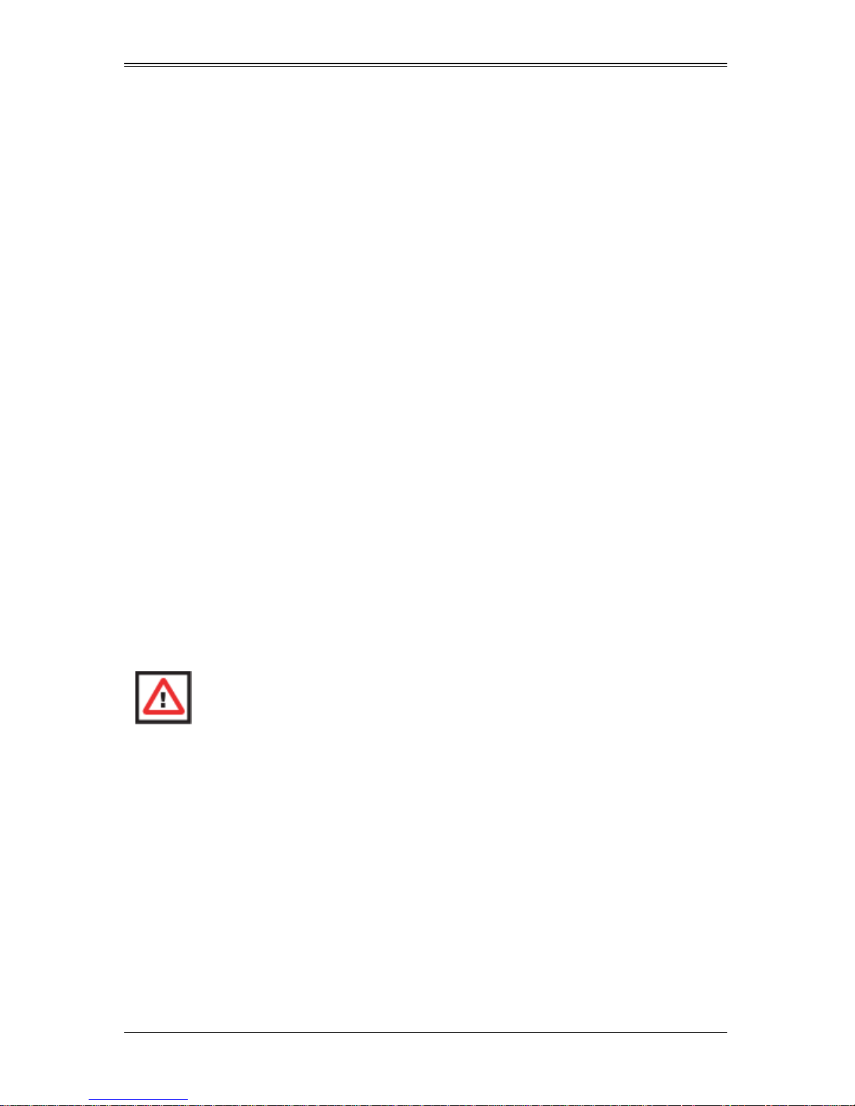
The SBI-7125W-S6 blade module is a compact self-contained server that connects into
a pre-cabled enclosure that provides power, cooling, management and networking
functions. One enclosure for the SBI-7125W-S6 blade module can hold ten blade units.
In this manual, “blade system” refers to the entire system (including the enclosure and
blades units), “blade” or “blade unit” refers to a single blade module and “blade
enclosure” is the chassis that the blades, power supplies and modules are housed in.
Please refer to our web site for information on operating systems that have been
certified for use with the SuperBlade (www.supermicro.com/products/superblade/).
1-2 Product Checklist of Typical Components
Your blade module ships with its mainboard already installed in its chassis. Memory,
hard disk drives and the CPU must all be installed by the user after shipment. See
Chapter 3: "Setup and Installation" on page 3-1 for details on installation of these
components.
Aside from the blade module unit itself, the following optional add-on cards may be
ordered for your blade module:
• Blade IPMI Add-on Card: AOC-SIMPL
• Mezzanine Cards (with Infiniband Switch): AOC-IBH-001, AOC-IBH-002 or
AOC-IBH-003
See the Supermicro website and the SuperBlade Network Modules User’s Manual on
your SuperBlade system’s CD-ROM for more details on these add-on cards.
1-1
SBI-7125W-S6 Blade Module User’s Manual
1-3 Blade Module Features
Table 1-1 lists the main features of the SBI-7125W-S6 blade module. See the
proceeding section for components typically included in a blade system and other
optional components. Specific details on the SBI-7125W-S6 blade module is found in
Chapter 4: "Blade Module Features" on page 4-1.
Table 1-1. SBI-7125W-S6 Blade Specification Features
Mainboard
Processors
FSB Speed 1600/1333/1066 MHz front side (system) bus speed
Chipset Intel 5400 MCH/ESB2
Graphics Controller ATI ES1000 with 32 MB graphics
BIOS 16 Mb Phoenix® Flash ROM
Memory Capacity
SATA Controller LSI SAS 1078 controller for six Serial ATA drives
Hard Drive Bays Six (6) hot-swap drive bays for 2.5" SATA disk drives
B7DW3 (proprietary form factor)
Chassis Dimensions (HxWxD): 11.32” x 1.67” x 18.9”
Single or dual Intel™ Xeon® 5400/5300/5200/5100/5000 sequence
processors. Please refer to our web site for a complete listing of supported
processors.
Eight 240-pin DIMM sockets supporting up to 64 GB of ECC FBD
DDR2-800/667/533 SDRAM.
Processors
The SBI-7125W-S6 blade module supports up to dual 771-pin Intel Xeon 5400/5300/
5200/5100/5000 series processors.
Refer to the Supermicro web site for a complete listing of supported processors (http://
www.supermicro.com/products/superblade). Please note that you will need to check the
detailed specifications of a particular blade module for a list of the CPUs it supports.
Details on installation of the processor into the SBI-7125W-S6 blade module are found
in Chapter 3: "Setup and Installation" on page 3-1.
Memory
The SBI-7125W-S6 blade module has eight 240-pin DIMM sockets that can support up
to 64 GB of ECC FBD (Fully Buffered DIMM) DDR2-800/667/533 SDRAM. Memory is
interleaved, which requires modules of the same size and speed to be installed in
groups (of two or three).
Please refer to the Supermicro web site for a list of supported memory
(www.supermicro.com/products/superblade). The detailed specifications for a blade
module will contain a link to a list of recommended memory sizes and manufacturers.
Details on installation of memory modules into the SBI-7125W-S6 blade module are
found in Chapter 3: "Setup and Installation" on page 3-1.
1-2
Chapter 1: Introduction
Storage
The SBI-7125W-S6 blade module can have six 2.5-inch SATA (Serial ATA) hard disk
drives in front-mounted easy removable carriers. See Chapter 3: "Setup a nd
Installation" on page 3-1 for storage installation details.
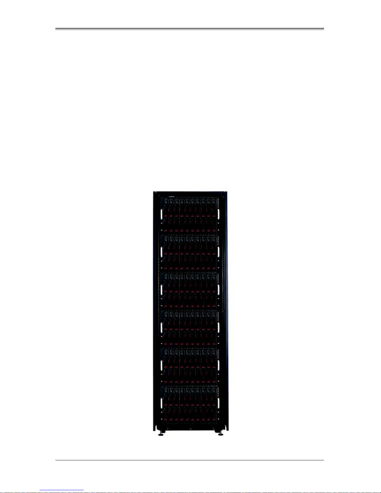
Density
A maximum of ten blade modules may be installed into a single blade enclosure. Each
blade enclosure is a 7U form factor, so a standard 42U rack may accommodate up to six
enclosures with 60 blade modules, or the equivalent of 60 1U servers. With the inclusion
of six CMM modules, twelve Gigabit Ethernet switches and six InfiniBand switches, this
would occupy up to 84U space in a conventional 1U server configuration.
Figure 1-1 displays a view of a full rack with six blade enclosures in it, each with ten
blades to an enclosure.
Figure 1-1. Full Rack of Blade Enclosures and Blade Servers
1-3

SBI-7125W-S6 Blade Module User’s Manual
1-4 Contacting Supermicro
Headquarters
Address: Super Micro Computer , Inc.
980 Rock Ave.
San Jose, CA 95131 U.S.A.
Tel: +1 (408) 503-8000
Fax: +1 (408) 503-8008
Email:
Web Site: www.supermicro.com
marketing@supermicro.com (General Information)
support@supermicro.com (Technical Support)
Europe
Address: Super Micro Computer B.V.
Het Sterrenbeeld 28, 5215 ML
‘s-Hertogenbosch, The Netherlands
Tel: +31 (0) 73-6400390
Fax: +31 (0) 73-6416525
sales@supermicro.nl (General Information)
Email:
support@supermicro.nl (Technical Support)
rma@supermicro.nl (Customer Support)
Asia-Pacific
Address: Super Micro Computer , Inc.
4F, No. 232-1, Liancheng Rd.
Chung-Ho 235, Taipei County
Taiwan, R.O.C.
Tel: +886-(2) 8226-3990
Fax: +886-(2) 8226-3991
Web Site: www.supermicro.com.tw
Technical Support:
Email: support@supermicro.com.tw
Tel: +886-2-8228-1366, ext. 132 or 139
1-4

Chapter 2
System Safety
2-1 Electrical Safety Precautions
Basic electrical safety precautions should be followed to protect yourself from harm and
the SuperBlade from damage:
• Be aware of how to power on/off the enclosure power supplies and the individual
blades as well as the room's emergency power-off switch, disconnection switch or
electrical outlet. If an electrical accident occurs, you can then quickly remove power
from the system.
• Do not work alone when working with high voltage components.
• Power should always be disconnected from the blade module when removing or
installing such system components as the mainboard, memory modules and
processors.
• When working around exposed electrical circuits, another person who is familiar
with the power-off controls should be nearby to switch off the power if necessary.
• Use only one hand when working with powered-on electrical equipment. This is to
avoid making a complete circuit, which will cause electrical shock. Use extreme
caution when using metal tools, which can easily damage any electrical components
or circuit boards they come into contact with.
• Do not use mats designed to decrease electrostatic discharge as protection from
electrical shock. Instead, use rubber mats that have been specifically designed as
electrical insulators.
• The power supply power cords must include a grounding plug and must be plugged
into grounded electrical outlets. Power input requires 110-240 V AC, depending upon
your power supply module.
• Mainboard Battery: This battery must be replaced only with the same or an
equivalent type recommended by the manufacturer (CR2032 Lithium 3V battery).
Dispose of used batteries according to the manufacturer's instructions.
WARNING: There is a danger of explosion if the onboard battery is installed
upside down, which will reverse its polarities.
• Mainboard replaceable soldered-in fuses: Self-resetting PTC (Positive Temperature
Coefficient) fuses on the mainboard must be replaced by trained service technicians
only. The new fuse must be the sa me or equivalent as the one replaced. Contact
technical support for details and support.
2-1

SBI-7125W-S6 Blade Module User’s Manual
2-2 General Safety Precautions
Follow these rules to ensure general safety:
• Keep the area around the SuperBlade clean and free of clutter.
• Place the blade module cover and any system components that have been removed
away from the system or on a table so that they won't accidentally be stepped on.
• While working on the system, do not wear loose clothing such as neckties and
unbuttoned shirt sleeves, which can come into contact with electrical circuits or be
pulled into a cooling fan.
• Remove any jewelry or metal objects from your body, which are excellent metal
conductors that can create short circuits and harm you if they come into contact with
printed circuit boards or areas where power is present.
• After accessing the inside of the system, replace the blade module's cover before
installing it back into the blade enclosure.
2-3 Electrostatic Discharge Precautions
Electrostatic discharge (ESD) is generated by two objects with different electrical
charges coming into contact with each other. An electrical discharge is created to
neutralize this difference, which can damage electronic components and printed circuit
boards.
The following measures are generally sufficient to neutralize this difference before
contact is made to protect your equipment from ESD:
• Use a grounded wrist strap designed to prevent static discharge.
• Keep all components and printed circuit boards (PCBs) in their antistatic bags until
ready for use.
• Touch a grounded metal object before removing the board from the antistatic bag.
• Do not let components or PCBs come into contact with your clothing, which may
retain a charge even if you are wearing a wrist strap.
• Handle a board by its edges only; do not touch its components, peripheral chips,
memory modules or contacts.
• When handling chips or modules, avoid touching their pins.
• Put the mainboard and peripherals back into their antistatic bags when not in use.
• For grounding purposes, make sure the blade enclosure provides excellent
conductivity between the power supplies, the blade modules and the mainboard.
2-4 Operating Precautions
Care must be taken to assure that the cover of the blade unit is in place when the blade
is operating to assure proper cooling. Out of warranty damage to the blade can occur if
this practice is not strictly followed.
Any drive carrier without a hard drive installed must remain fully installed in the drive bay
when the blade module is operating to ensure proper airflow.
2-2

Chapter 3
Setup and Installation
3-1 Overview
This chapter covers the setup and installation of the blade module and its components.
3-2 Installing Blade Modules
Up to ten SBI-7125W-S6 blade modules may be installed into a single blade enclosure
(depending upon your enclosure and blad). Blade modules with Windows and Linux
operating systems may be mixed together in the same blade enclosure.
Powering Up a Blade Unit
Each blade unit may be powered on and off independently from the rest of the blades
installed in the same enclosure. A blade unit may be powered up in two ways:
• Press the power button on the blade unit.
• Use IPMIView or the web-browser based management utility to apply power using
either a CMM module, or by the use of an installed SIMBL add-on card in the blade
module.
Powering Down a Blade Unit
A blade unit may be powered down in either of five ways:
• Press the power button on the blade unit.
• Use IPMIView or the web-browser based management utility to power down (if you
have Operator or Admin privileges on the CMM).
• Use IPMItool when connected to the CMM to power down (if you have Operator or
Admin privileges on the CMM).
• Use IPMIview or a browser connected to the SIMBL card attached to the blade to
power down.
• Use IPMItool to use a Command Line Interface (CLI) to the SIMBL (if you have
Operator or Admin privileges).
Removing a Blade Unit from the Enclosure
Although the blade system may continue to run, individual blades should always be
powered down before removing them from the enclosure.
3-1

SBI-7125W-S6 Blade Module User’s Manual
Removing a Blade Unit from the Enclosure
1. Power down the blade unit (see "Powering Down a Blade Unit" above).
2. Squeeze both handles to depress the red sections then pull out both handles
completely and use them to pull the blade unit from the enclosure.
NOTE: Blade Modules can be Hot-Plugged from the enclosure.
Removing/Replacing the Blade Cover
The blade cover must be removed to access the mainboard when you need to install or
remove processors, memory units, the onboard battery and so on.
Removing/Replacing the Blade Cover
1. Remove the blade unit from the enclosure (see "Removing a Blade Unit from the
Enclosure" above).
2. Depress the two buttons on the cover while pushing the cover toward the rear of the
blade unit. When it stops, lift the cover off the blade unit.
3. To replace the cover, fit the six grooves in the cover into the studs in the sides of the
blade, then slide the cover toward the front of the blade to lock it into place.
Installing a Blade Unit into the Enclosure
Make sure the cover of the blade unit has been replaced first before installing a blade
unit in the enclosure.
Installing a Blade Unit into the Enclosure
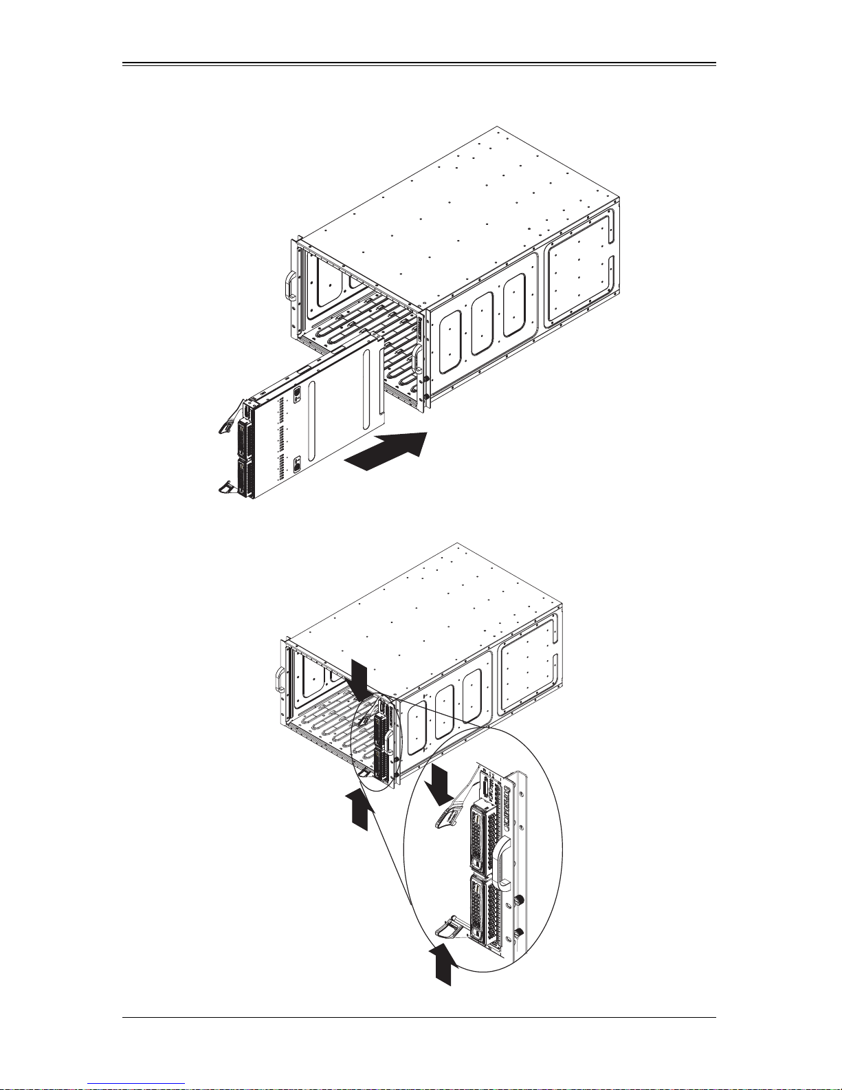
1. Slowly push the blade unit into its bay with the handles fully pulled out (see
Figure 3-1).
2. When the blade stops, push the handles back in to their locked position, making
sure the notches in both handles catch the lip of the enclosure (see Figure 3-2).
NOTE: Blade Modules can be Hot-Plugged into the enclosure.
WARNING: Use extreme caution when inserting a blade module into the
enclosure. If the blade's power connector becomes damaged, it can damage
pins on other blade bays that it is inserted into.
3-2
Chapter 3: Setup and Installation
Figure 3-1. Inserting a Blade into the Enclosure
Figure 3-2. Locking the Blade into Position
3-3
SBI-7125W-S6 Blade Module User’s Manual
3-3 Processor Installation
One or two processors may be installed to the mainboard of each blade unit. See
Chapter 1 for general information on the features of the blade unit and the Supermicro
web site for further details including processor, memory and operating system support.
WARNING: This action should only be performed by a trained service
technician. Allow the processor heatsink to cool before removing it.
Removing a Processor
1. Power down and remove the blade unit from the enclosure (see Section 3-2:
Installing Blade Modules on page 3-1 for details).
2. Remove the cover of the blade unit (see "Removing/Replacing the Blade Cover" on
page 3-2).
3. Loosen the four screws that secure the heatsink to the mainboard.
4. Remove the heatsink by gently rotating it back-and-forth sideways with your fingers
to release it from the processor. Set the heatsink aside and upside-down so that
nothing comes into contact with the thermal grease on its underside.
5. Raise the lever of the processor socket up until the processor is released from the
socket, then lift the silver cover plate and remove the processor.
WARNING: This action should only be performed by a trained service
technician.
Installing a Processor
1. If present, remove the protective black PnP cap from the processor socket.
2. Raise the lever of the processor socket until it reaches its upper limit.
3. Lift the silver cover plate completely up and out of the way.
NOTE: Be careful not to damage the pins protruding from the CPU socket.
4. Align pin 1 of the processor with pin 1 of the socket (both are marked with a small
gold triangle) and gently seat the processor into the socket (Figure 3-3).
5. Check to make sure the processor is flush to the socket and fully seated.
6. Lower the socket lever until it locks.
7. To install the heatsink, apply thermal grease to the top of the processor. (If
reinstalling a heatsink, first clean off the old thermal grease with a clean, lint-free
cloth.)
3-4
Chapter 3: Setup and Installation
8. Place the heatsink on the processor then tighten two diagonal screws until snug,
then the other two screws.
9. When all four screws are snug, tighten them all to secure the heatsink to the
mainboard.
NOTE: Do not overtighten the screws as this may damage the processor or the
heatsink.
10. Replace the cover on the blade unit and finish by installing the unit back into the
blade enclosure.
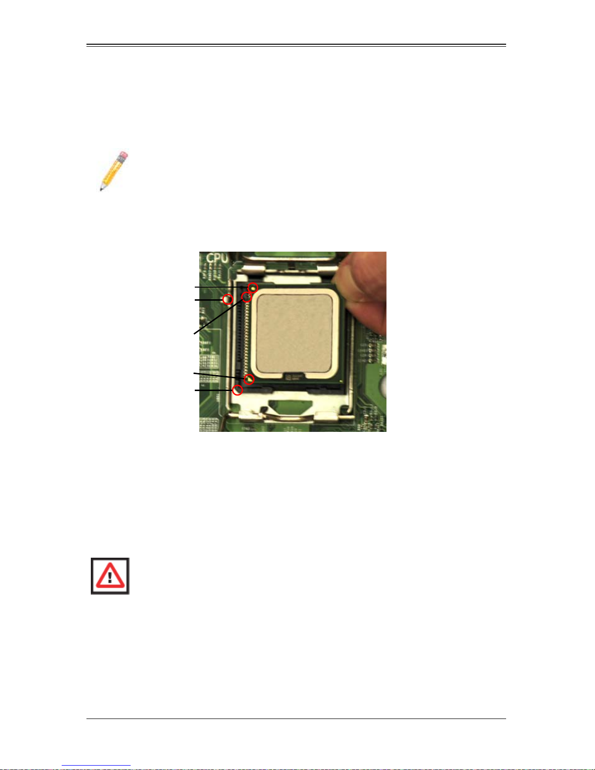
Figure 3-3. Installing a Processor in a Socket
Gold dot
Socket key
CPU key
CPU pin
Notched corner
3-4 Onboard Battery Installation
A battery is included on the mainboard to supply certain volatile memory components
with power when power has been removed from the blade module. If this battery dies, it
must be replaced with an equivalent CR2032 Lithium 3V battery. Dispose of used
batteries according to the manufacturer's instructions. See Figure 3-4 for a diagram of
installing a new onboard battery.
WARNING: There is a danger of explosion if the onboard battery is installed
upside down, which reverses its polarities.
3-5

SBI-7125W-S6 Blade Module User’s Manual
Figure 3-4. Installing the Onboard Battery
Lithium Battery
Battery Holder
3-5 Memory Installation
The mainboard of each blade unit must be populated with DIMMs (Dual In-line Memory
Modules) to provide system memory. The DIMMs should all be of the same size and
speed and from the same manufacturer due to compatibility issues. See details
below on supported memory and our web site (www.supermicro.com/products/
superblade for recommended memory.
Populating Memory Slots
The mainboard of a SBI-7125W-S6 blade module has eight memory slots, depending
upon the blade model. Both interleaved and non-interleaved memory are supported, so
you may populate any number of DIMM slots.
Populating two slots at a time (DIMM1A + DIMM2A, DIMM3A + DIMM4A, etc.) with
memory modules of the same size and of the same type will result in dual-channel,
interleaved memory, which is faster than single-channel, non-interleaved memory. See
Table 3-1: "Populating Eight Memory Slots for Interleaved Operation" on page 3-6 for
details.
For an interleaved configuration, memory modules of the same size and speed
must be installed in pairs. You should not mix DIMMs of different sizes and
speeds.
Table 3-1. Populating Eight Memory Slots for Interleaved Operation
Number
of DIMMs
2 DIMMs 1A --- 2A --- --- --- --- --4 DIMMs 1A --- 2A --- 3A --- 4A --6 DIMMs 1A 1B 2A 2B 3A 3B --- --8 DIMMs 1A 1B 2A 2B 3A 3B 4A 4B
Channel 0 Channel 1 Channel 2 Channel 3
NOTE: The DIMM slot number specified in Table 3-1 equals the DIMM slot to
be populated. A “---” indicates that the DIMM slot should be left unpopulated.
3-6
Chapter 3: Setup and Installation
NOTE: Though multiple DIMM memory module types and speeds may be
supported, you need to use DIMM memory modules of the same speed and
type.
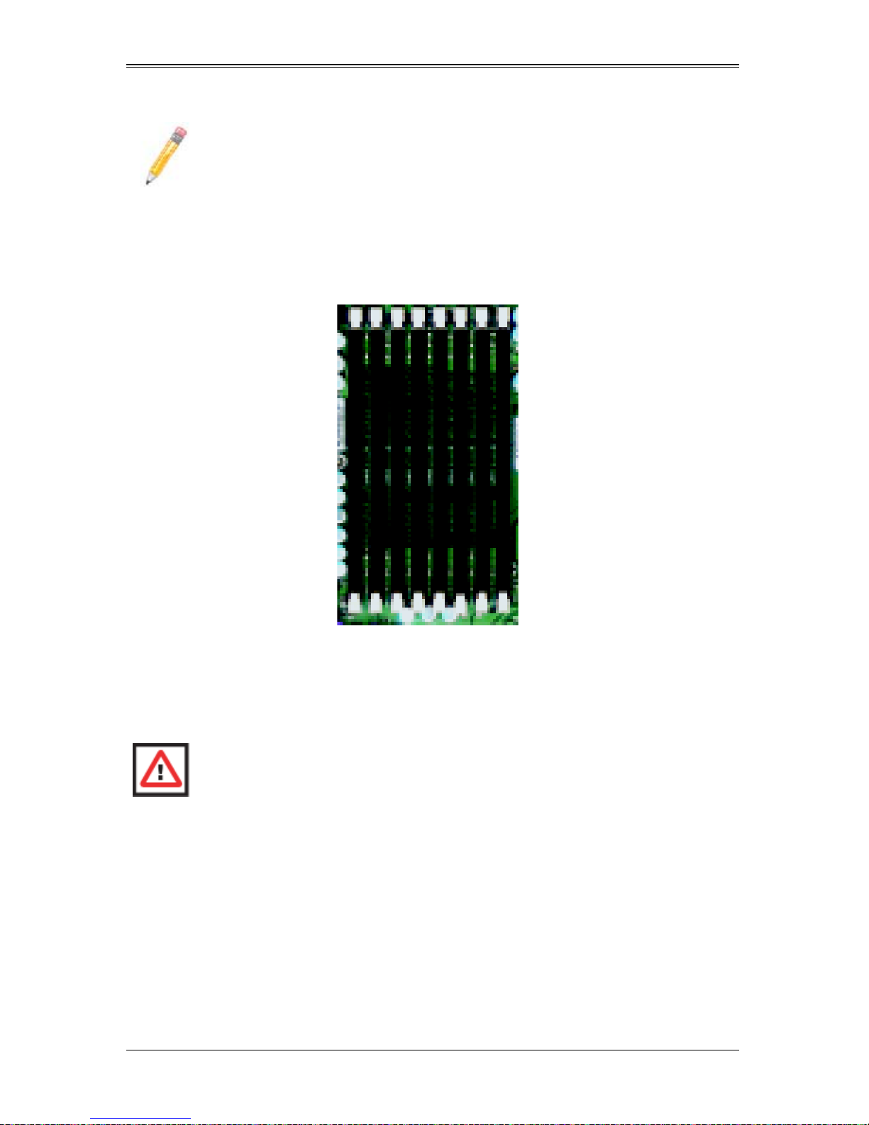
Figure 3-5. 8-slot DIMM Numbering
DIMM1A
DIMM1B
DIMM2A
DIMM2B
DIMM3A
DIMM3B
DIMM4A
DIMM4B
Center of Board
Toward CPU1
Edge of Board
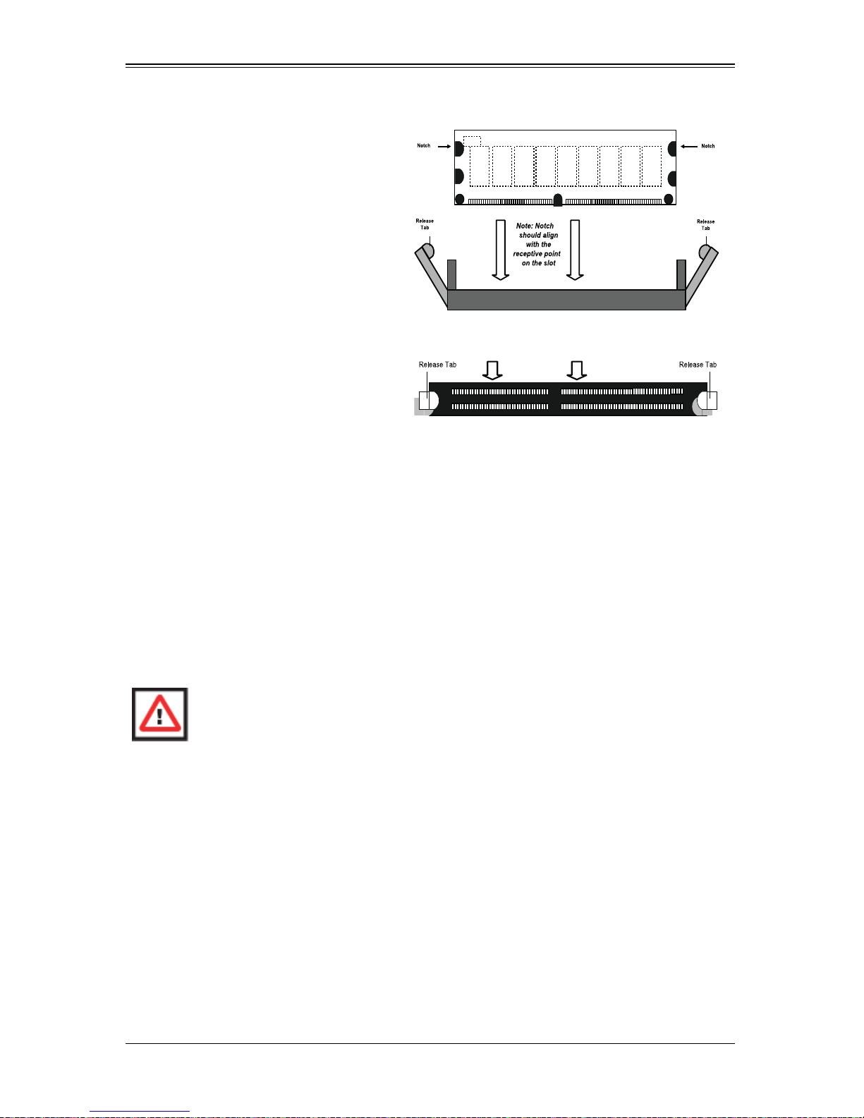
DIMM Installation
WARNING: Exercise extreme care when installing or removing DIMM modules
to prevent any possible damage.
Installing DIMM Memory Modules
1. Power down the blade module (see "Powering Down a Blade Unit" on page 3-1).
2. Remove the blade from the enclosure and the cover from the blade (see
"Removing/Replacing the Blade Cover" on page 3-2).
3. Remove the air shroud that covers the DIMM slots.
4. Insert each DIMM vertically into its slot, starting with slots 1A and 2A. Pay attention
to the notch along the bottom of the module to prevent inserting the DIMM
incorrectly (see Figure 3-6).
3-7
SBI-7125W-S6 Blade Module User’s Manual
Figure 3-6. Installing a DIMM into a Memory Slot
T o Install: Insert module vertically
and press down until it snaps into
place. Pay attention to the bottom
notch.
DDR2 DIMM
To Remove: Use your thumbs to
Top View of DDR2 DIMM Slot
gently push each release tab
outward to free the DIMM from the
slot.
5. Gently press down on the DIMM until it snaps into place in the slot. Repeat for all
modules (see Table 3-1 for installing DIMMs into the slots in the correct order).
6. Replace the air shroud and the blade cover and install the blade module back into
the enclosure.
7. Power up the blade unit (see "Powering Up a Blade Unit" on page 3-1).
3-6 Hard Disk Drive Installation
Hard disk drives are installed in “carriers” which are hot-swappable and can be removed
or replaced without powering down the blade unit they reside in. A blade module needs
a hard disk drive with an operating system installed to operate.
WARNING: To maintain proper airflow, both hard drive bays must have drive
carriers inserted during operation whether or not a drive is installed in the carrier.
To remove a hard drive carrier, do the following:
Removing a Hard Drive Carrier
1. Locate the colored “Open” button at the bottom of the drive carrier and press it with
your thumb. This action releases the drive carrier from the drive bay.
2. Pull the release handle out about 45-degrees, then use it to pull the drive carrier out.
To Install a hard drive, use the following procedure:
3-8
Chapter 3: Setup and Installation
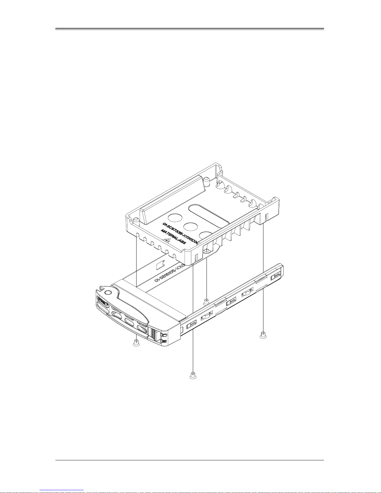
Installing a Hard Drive
1. Remove a blank drive carrier from the blade (see removal procedure above).
2. Insert a drive into the carrier with the PCB side facing down and the connector end
toward the rear of the carrier.
3. Align the drive in the carrier so that the screw holes of both line up.
4. Secure the drive to the carrier with six screws as shown in Figure 3-7.
5. Insert the drive carrier into its slot keeping the Open button at the bottom. When the
carrier reaches the rear of the bay the release handle will retract.
6. Push the handle in until you hear the carrier click into its locked position.
Figure 3-7. Installing a Hard Drive in a Carrier
3-9
SBI-7125W-S6 Blade Module User’s Manual
3-7 Installing the Operating System
An operating system (OS) must be installed on each blade module. Blades with
Microsoft Windows OS and blades with Linux OS can both occupy and operate within
the same blade enclosure. Refer to the SuperMicro web site for a complete list of
supported operating systems.
There are several methods of installing an OS to the blade modules.
Installing with an External USB CD-ROM Drive
The most common method of installing the OS is with an external USB CD-ROM drive.
Take the following steps to install the OS to a blade module:
WARNING: Installing the OS from an external CD-ROM drive may take several
hours to complete.
1. Connect an SUV cable (Serial port/USB port/Video port cable) to the KVM
connector on the front of the blade module. You will then need to attach a USB hub
to the USB port on this cable to provide multiple USB ports.
2. Connect the external CD-ROM drive, a USB keyboard and a mouse to the USB hub.
You will also need to connect a monitor to the video connector on the SUV cable.
Turn on the blade module.
3. Insert the CD containing the OS into the CD-ROM drive.
4. Follow the prompts to begin the installation.
Installing via PXE Boot
PXE (Preboot Execution Environment) is used to boot a computer over a network. To
install the OS via PXE, the following conditions must be met:
1. The PXE B
2. A PXE server has been configured (this can be another blade in the system).
3. The PXE server must be connected over a network to the blade to be booted.
4. The blade has only non-partitioned/unformatted hard drives installed and no
bootable devices attached to it.
Once these conditions are met, make sure the PXE server is running. Then turn on the
blade on which you wish to boot and/or install the OS. The BIOS in the blade will look at
all bootable devices and finding none will connect to the PXE server to begin the boot/
install.
OOT option in BIOS must be enabled.
3-10

Chapter 3: Setup and Installation
Installing via Virtual Media (Drive Redirection)
You can install the OS via Virtual Media through either the IPMIview (Java based client
utility), IPMItool or the Web-based Management Utility. With this method, the OS is
installed from an ISO image that resides on another system/blade.
Refer to the manuals on your SuperBlade CD-ROM for further details on the Virtual
Media (CD-ROM or Drive Redirection) sections of these two utility programs.
3-8 Management Software
System management may be performed with either of three software packages:
IPMIview, IPMItool or a Web-based Management Utility. These are designed to provide
an administrator with a comprehensive set of functions and monitored data to keep tabs
on the system and perform management activities.
Refer to the manuals on your SuperBlade CD-ROM for further details on the various
functions provided by these management programs.
3-9 Configuring and Setting up RAID
Each blade module that supports two or more hard drives may be used to create a RAID
array. The procedures for doing this vary depending upon the blade model chosen for
your SuperBlade system.
See Chapter 5 for details on how to configure and set up RAID on your blade module.
3-11
 Loading...