

Supermicro PIIISEA, PIIISED User Manual

®
SUPER PIIISED
SUPER PIIISEA
USER’S AND BIOS
MANUAL
Revision 1.1
SUPER

The information in this User’s Manual has been carefully reviewed and is believed to be
accurate. The vendor assumes no responsibility for any inaccuracies that may be contained
in this document, makes no commitment to update or to keep current the information in this
manual, or to notify any person or organization of the updates.
Please Note: For the
most up-to-date version of this manual, please see our web site at
www.supermicro.com.
SUPERMICRO COMPUTER reserves the right to make changes to the product described in
this manual at any time and without notice. This product, including software, if any, and
documentation may not, in whole or in part, be copied, photocopied, reproduced, translated or
reduced to any medium or machine without prior written consent.
IN NO EVENT WILL SUPERMICRO COMPUTER BE LIABLE FOR DIRECT, INDIRECT,
SPECIAL, INCIDENTAL, OR CONSEQUENTIAL DAMAGES ARISING FROM THE USE OR
INABILITY TO USE THIS PRODUCT OR DOCUMENTATION, EVEN IF ADVISED OF THE
POSSIBILITY OF SUCH DAMAGES. IN PARTICULAR, THE VENDOR SHALL NOT HAVE
LIABILITY FOR ANY HARDWARE, SOFTWARE, OR DATA STORED OR USED WITH THE
PRODUCT, INCLUDING THE COSTS OF REPAIRING, REPLACING, INTEGRATING,
INSTALLING OR RECOVERING SUCH HARDWARE, SOFTWARE, OR DATA.
Unless you request and receive written permission from SUPER MICRO COMPUTER, you
may not copy any part of this document.
Information in this document is subject to change without notice. Other products and
companies referred to herein are trademarks or registered trademarks of their respective
companies or mark holders.
Copyright © 1999 by SUPER MICRO COMPUTER INC.
All rights reserved.
Printed in the United States of America.

Preface
About This Manual
This manual is written for system integrators, PC technicians and
knowledgeable PC users. It provides information for the installation and use
of the SUPER PIIISED/PIIISEA motherboard. The SUPER PIIISED/PIIISEA
supports Pentium® III 450-600 MHz, Pentium II 233-450 MHz and SEPP
CeleronTM 266-466 MHz processors .
Pentium II/III processors with the Dual Independent Bus (DIB) architecture are
housed in a package called a Single Edge Contact Cartridge (S.E.C.C.) .
Celeron processors that are packaged in the SEPP (Single Edge Processor
Package) cartridge are also supported by the PIIISED/PIIISEA. These cartridge packages and their associated "Slot 1" infrastructure will provide the
headroom for future high-performance processors.
Manual Organization
Chapter 1 includes a checklist of what should be included in your mainboard
box, describes the features, specifications and performance of the SUPER
PIIISED/PIIISEA mainboard and provides detailed information about the
chipset.
Chapter 2 begins with instructions on handling static-sensitive devices. Read
this chapter when you want to install the processor and DIMM memory modules and when mounting the mainboard in the chassis. Also refer to this
chapter to connect the floppy and hard disk drives, the IDE interfaces, the
parallel and serial ports and the twisted wires for the power supply, the reset
button, the keylock/power LED, the speaker and the keyboard.
If you encounter any problems, see Chapter 3, which describes troubleshoot-
ing procedures for the video, the memory and the setup configuration stored
in CMOS. For quick reference, a general FAQ [Frequently Asked Questions]
section is provided. Instructions are also included for contacting technical
support. In addition, you can visit our web site at www.supermicro.com/
techsupport.htm for more detailed information.
Chapter 4 includes an introduction to BIOS and provides detailed information
on running the CMOS Setup utility.
iii
Preface

Appendix A provides information on BIOS error beep codes and messages.
Appendix B lists post diagnostic error messages.
iv
SUPER PIIISED/PIIISEA User’s Manual

Table of Contents
v
Table of Contents
Preface
About This Manual ...................................................................................................... ii i
Manual Organization ................................................................................................... i ii
Chapter 1: Introduction
1-1 Overview .......................................................................................................... 1 -1
Checklist .................................................................................................... 1- 1
Contacting Supermicro ............................................................................. 1 -2
SUPER PIIISED Motherboard Image .................................................... 1- 4
SUPER PIIISEA Motherboard Image ..................................................... 1- 5
SUPER PIIISED Motherboard Layout ................................................... 1- 6
SUPER PIIISEA Motherboard Layout .................................................... 1 -8
810E Chipset: System Block Diagram ................................................. 1-10
Motherboard Features ........................................................................... 1-11
1-2 Chipset Overview .......................................................................................... 1-13
1-3 PC Health Monitoring................................................................................... 1-14
1-4 ACPI/PC 98 Features .................................................................................. 1-16
1-5 Power Supply ................................................................................................ 1-18
1-6 Super I/O ........................................................................................................ 1-19
Chapter 2: Installation
2-1 Static-Sensitive Devices ................................................................................ 2- 1
Precautions ............................................................................................... 2- 1
Unpacking ................................................................................................. 2 -1
2-2 Processor Installation .................................................................................... 2- 2
2-3 Mounting the Motherboard in the Chassis .................................................. 2-3
2-4 Installing DIMMs ............................................................................................. 2- 4
2-5 Port/Control Panel Connector Locations ..................................................... 2 -5
2-6 Connecting Cables ......................................................................................... 2 -6
Power Supply Connector ........................................................................ 2-6
Infrared Connector .................................................................................... 2- 6
PW_ON Connector .................................................................................... 2 -6
Reset Connector ...................................................................................... 2-7
Hard Drive LED ........................................................................................ 2 -7
Keylock/Power LED Connector .............................................................. 2-7
Speaker Connector .................................................................................. 2 -7
ATX PS/2 Keyboard and Mouse Ports ................................................. 2-7

SUPER PIIISED/PIIISEA User’s Manual
Universal Serial Bus ................................................................................ 2-8
Serial Ports ............................................................................................... 2-8
Wake-On-LAN ........................................................................................... 2 -8
Fan Headers ............................................................................................. 2 -8
CD Headers .............................................................................................. 2- 9
Overheat LED ............................................................................................ 2- 9
Chassis Intrusion ...................................................................................... 2 -9
2-7 Jumper Settings ............................................................................................ 2-10
Changing the CPU/FSB Speed............................................................ 2-10
CMOS Clear ............................................................................................. 2-11
AC'97 Enable/Disable ............................................................................. 2-11
Keyboard Wake-Up ................................................................................. 2-11
2-8 Parallel Port, AMR, Floppy and Hard Disk Drive Connections ............. 2-12
Parallel Port Connector ......................................................................... 2-13
Floppy Connector ................................................................................... 2-13
IDE Connectors ...................................................................................... 2-13
AMR Connector ....................................................................................... 2-14
2-9 Installing Software Dr ivers .......................................................................... 2-15
Chapter 3: Troubleshooting
3-1 Troubleshooting Procedures ......................................................................... 3 -1
Before Power On ...................................................................................... 3 -1
No Power ................................................................................................... 3-1
No Video .................................................................................................... 3-1
Memory Errors .......................................................................................... 3-2
Losing the System’s Setup Configuration ............................................ 3- 2
3-2 Technical Support Procedures ..................................................................... 3-2
3-3 Frequently Asked Questions ......................................................................... 3 -3
3-4 Returning Merchandise for Service ............................................................. 3- 6
Chapter 4: BIOS
4-1 Introduction....................................................................................................... 4 - 1
4-2 BIOS Features ................................................................................................. 4- 2
4-3 Running Setup ................................................................................................. 4 -2
Standard CMOS Setup ............................................................................. 4- 4
Advanced CMOS Setup ........................................................................... 4- 5
Advanced Chipset Setup ......................................................................... 4 -9
Power Management ................................................................................ 4-12
PCI/Plug and Play Setup ....................................................................... 4-16
vi

Table of Contents
Peripheral Setup ..................................................................................... 4-18
Auto-Detect Hard Disks ......................................................................... 4-21
Change User/Supervisor Password ...................................................... 4-21
Change Language Setting ..................................................................... 4-22
Auto Configuration with Optimal Settings ........................................... 4-22
Auto Configuration with Fail Safe Settings ......................................... 4-22
Save Settings and Exit ........................................................................... 4-22
Exit Without Saving ................................................................................ 4-22
Appendices:
Appendix A: BIOS Error Beep Codes and Messages .........................................A- 1
Appendix B: AMIBIOS Post Diagnostic Error Messages .................................... B -1
vii

Notes
SUPER PIIISED/PIIISEA User’s Manual

Chapter 1: Introduction
1-1
Introduction
Chapter 1
Introduction
1-1 Overview
Checklist
Congratulations on purchasing your computer motherboard from an acknowledged leader in the industry. Supermicro boards are designed with
the utmost attention to detail to provide you with the highest standards in
quality and performance.
Please check that the following items have all been included with your
motherboard. If anything listed here is damaged or missing, contact your
retailer.
One (1) Supermicro Mainboard
One (1) ATA66 ribbon cable for IDE devices
One (1) Floppy ribbon cable for floppy drives
One (1) Supermicro CD containing drivers and utilities
One (1) URM (Univeral Retention Mechanism for the CPU - preinstalled)
One (1) User's/BIOS Manual

SUPER PIIISED/PIIISEA Manual
1-2
Introduction
CONTACTING SUPERMICRO
Headquarters
Address: Super Micro Computer, Inc.
2051 Junction Avenue
San Jose, CA 95131 U.S.A.
Tel: +1 (408) 895-2001
Fax: +1 (408) 895-2008
E-mail: marketing@supermicro.com (General Information)
support@supermicro.com (Technical Support)
Web site: www.supermicro.com
European Office
Address: Super Micro Computer B.V.
Het Sterrenbeeld 28, 5215 ML,
's-Hertogenbosch, The Netherlands
Tel: +31 (0) 73-6400390
Fax: +31 (0) 73-6416525
E-mail: sales@supermicro.nl

Chapter 1: Introduction
1-3
Introduction
Notes
SUPER PIIISED/PIIISEA Manual
1-4
Introduction
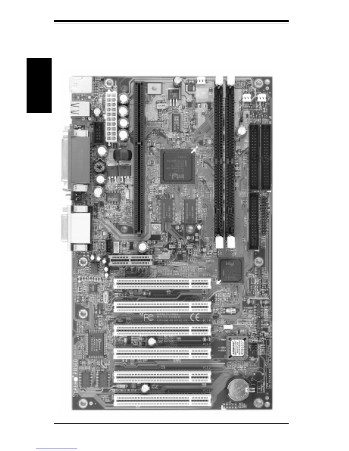
SUPER PIIISED
Figure 1-1. SUPER PIIISED Motherboard Image
Chapter 1: Introduction
1-5
Introduction
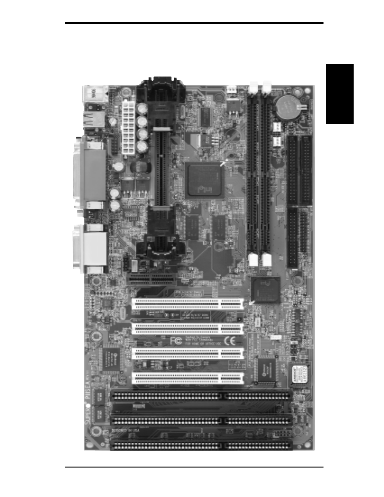
SUPER PIIISEA
Figure 1-2. SUPER PIIISEA Motherboard Image
SUPER PIIISED/PIIISEA Manual
1-6
Introduction
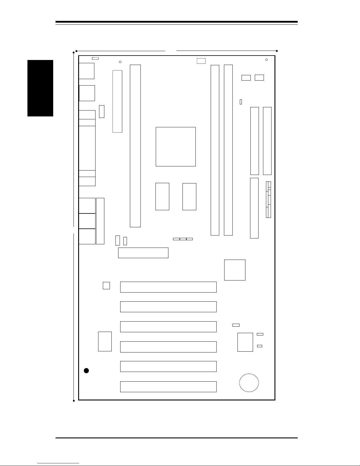
Figure 1-3. SUPER PIIISED Motherboard Layout
SUPER PIIISED
®
COM1
COM2
J30
KB/
MOUSE
J29
ATX POWER
J12
J13
J11
J32, J33
USB
FAN1
Bank0
Bank1
PCI 1
PCI 2
PCI 3
JF1
JF2
IR CON PW_ON
RESET
IDE LED/KEYLOCK/SPEAKER
JP26
J19
FLOPPY
IDE2
IDE1
11
J18
FA
N2: C
hassis Fan
1
WOL
FAN2
ICH
GMCH
J35
Parallel
Port
1
J28
11.6"
7.0"
J1
J9
BATTERY
JP
W
AK
E
1
1
1
LINE
OUT
LINE
IN
MIC
CD_1
DISPLAY
CACHE
CD
1
1
1
1
AMR
JBT1
BIOS
4 Mb
FWH
DISPLAY
CACHE
J4
VGA
GAME PORT
FAN
3: Therm
al C
ontrol Fan
FAN
1: C
P
U
Fan
CPU
J14
PCI 4
1
SUPER I/O
1
1
JOH
1
1
JP11
PCI 5
PCI 6
J11A
J12A
FAN3
1
JP28
JL1
1
JP12
AC'97 Audio
CODEC Chip

Chapter 1: Introduction
1-7
Introduction
Quick Reference
Jumpers Description Default Setting
JBT1 CMOS Clear (p. 2-11) Pin 1-2 (Normal)
JL1 Chassis Intrusion (p. 2-9) OFF (Disabled)
JP11, JP12 Front Side Bus Speed (p. 2-10) Both: Pins 1-2 (Auto)
JP28 AC'97 Enable/Disable (p. 2-11) Pin 1-2 (Enabled)
JPWAKE Keyboard Wake-Up (p. 2-11) Pin 1-2 (Disabled)
Connectors Description
AMR Audio Modem Riser (p. 2-14)
CD Audio CD Input (large connector) (p. 2-9)
CD_1 Audio CD Input (small connector) (p. 2-9)
COM1 COM1 Serial Port Connector (p. 2-8)
COM2 COM2 Serial Port Header (p. 2-8)
FAN1 CPU Fan Header (p. 2-8)
FAN2 Chassis Fan Header (p. 2-8)
FAN3 Thermal Control Fan Header (p. 2-8)
GAME Game Port
J18, J19 IDE Hard Disk Drive Connectors (p. 2-13)
J2 9 ATX Power Connector (p. 2-6)
J30 PS/2 Keyboard (lower)/Mouse (upper) (p. 2-7)
J32, J33 Universal Serial Bus Ports (p. 2-8)
J35 Parallel Printer Port (p. 2-13)
JF1, JF2 Front Control Panel (p. 2-5)
JOH Overheat LED Header (p. 2-9)
JP26 Floppy Disk Drive Connector (p. 2-13)
LINE IN Audio In Connector
LINE OUT Audio Out (Speaker) Connector
MIC Microphone Input
VGA (J4) Video (Monitor) Port
WOL Wake-on-LAN Header (p. 2-8)
Also see the figures on page 2-5 for the locations of the I/O ports
and Front Control Panel connectors.
SUPER PIIISED/PIIISEA Manual
1-8
Introduction
®
COM1
COM2
J30
KB/
MOUSE
J29
ATX POWER
J12
J13
J11
J32, J33
USB
FAN1
B
ank0
Bank1
PCI 1
JF1
JF2
IR CON PW_ON
RESET
IDE LED/KEYLOCK/SPEAKER
JP26
J19
FLOPPY
IDE2
IDE1
11
J18
FAN
2: C
hassis Fan
1
WOL
FAN2
ICH
GMCH
J35
Parallel
Port
1
J28
12"
7.0"
J1
J9
BATTERY
JP
W
A
K
E
1
1
1
LINE
OUT
LINE
IN
MIC
CD_1
DISPLAY
CACHE
CD
1
1
1
AMR
JBT1
BIOS
4 Mb
FWH
DISPLAY
CACHE
J4
VGA
GAME PORT
FAN
3: Therm
al C
ontrol Fan
FAN
1: C
PU
Fan
CPU
J14
PCI 2
1
SUPER I/O
1
1
1
JOH
1
1
JP11
PCI 3
PCI 4
U58
1
JP28
JL1
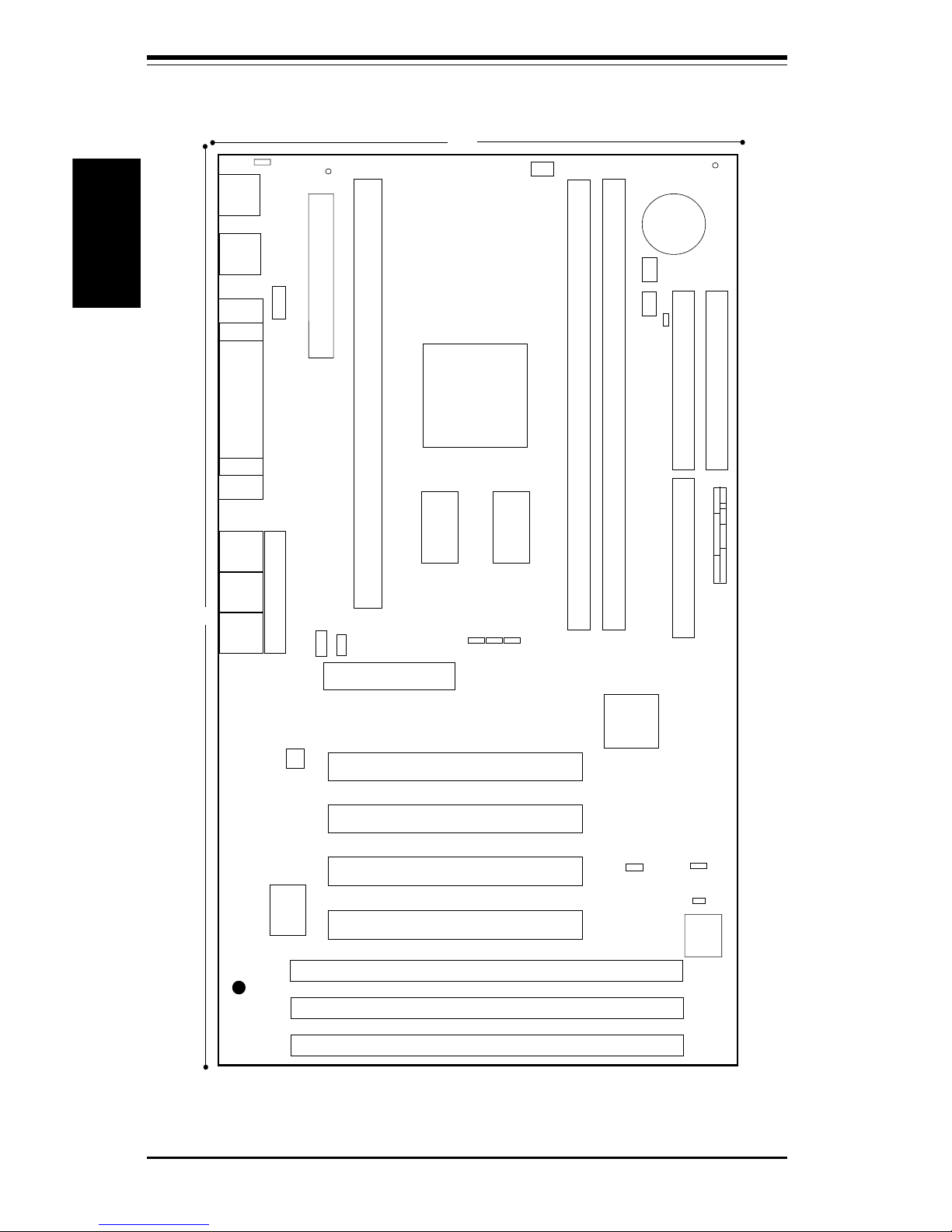
Figure 1-4. SUPER PIIISEA Motherboard Layout
SUPER PIIISEA
FAN3
1
1
JP12
ISA 1
1
ISA 2
ISA 3
U57
U56
AC'97 Audio
CODEC Chip

Chapter 1: Introduction
1-9
Introduction
Quick Reference
Jumpers Description Default Setting
JBT1 CMOS Clear (p. 2-11) Pin 1-2 (Normal)
JL1 Chassis Intrusion (p. 2-9) OFF (Disabled)
JP11, JP12 Front Side Bus Speed (p. 2-10) Both: Pins 1-2 (Auto)
JP28 AC'97 Enable/Disable (p. 2-11) Pin 1-2 (Enabled)
JPWAKE Keyboard Wake-Up (p. 2-11) Pin 1-2 (Disabled)
Connectors Description
AMR Audio Modem Riser (p. 2-14)
CD Audio CD Input (large connector) (p. 2-9)
CD_1 Audio CD Input (small connector) (p. 2-9)
COM1 COM1 Serial Port Connector (p. 2-8)
COM2 COM2 Serial Port Header (p. 2-8)
FAN1 CPU Fan Header (p. 2-8)
FAN2 Chassis Fan Header (p. 2-8)
FAN3 Thermal Control Fan Header (p. 2-8)
GAME Game Port
J18, J19 IDE Hard Disk Drive Connectors (p. 2-13)
J2 9 ATX Power Connector (p. 2-6)
J30 PS/2 Keyboard (lower)/Mouse (upper) (p. 2-7)
J32, J33 Universal Serial Bus Ports (p. 2-8)
J35 Parallel Printer Port (p. 2-13)
JF1, JF2 Front Control Panel (p. 2-5)
JOH Overheat LED Header (p. 2-9)
JP26 Floppy Disk Drive Connector (p. 2-13)
LINE IN Audio In Connector
LINE OUT Audio Out (Speaker) Connector
MIC Microphone Input
VGA (J4) Video (Monitor) Port
WOL Wake-on-LAN Header (p. 2-8)
Also see the figures on page 2-5 for the locations of the I/O ports
and Front Control Panel connectors.

SUPER PIIISED/PIIISEA Manual
1-10
Introduction
Figure 1-5. 810E Chipset:
System Block Diagram
GMCH
421 BGA
Pentium III/II
or
Celeron SEPP
CPU
ICH
241 BGA
SDRAM
133/100/66 MHz Host Bus
PCI Slots
USB
ATA66 IDE
Ports
BIOS 4Mb
FWH
4MB Display Cache
33 MHz PCI Bus
100 MHz SDRAM Bus
SuperI/O
LPC
1.5 Mb/sec
AC'97 AMR
133/100 MHz Bus
Note: This is a general block diagram and may not
represent the actual number of PCI/ISA slots on your
motherboard. See the following page for the actual
specifications of each motherboard.

Chapter 1: Introduction
1-11
Introduction
Features of the PIIISED/PIIISEA Motherboard
CPU
• Pentium III 450-600 MHz and Pentium II 350-450 MHz processors at 100
MHz bus speed and Pentium II 233-333 MHz and Celeron SEPP 266-466
MHz processors at 66 MHz bus speed.
Note: 133 MHz will be supported by future Intel 133 MHz FSB processors.
Memory
• Two 168-pin DIMM sockets supporting up to 512 MB unbuffered 3.3V
SDRAM
Note: Because the 810E chipset features a 100 MHz memory bus, the SDRAM must be PC-100
compliant DIMMs regardless of the front side bus speed being used.
Chipset
• Intel 810E (see page 1-13 for details)
Expansion Slots
PIIISED PIIISEA
• 6 PCI slots • 4 PCI slots
• 3 ISA slots (1 PCI/ISA slot shared)
• 1 AMR slot • 1 AMR slot
BIOS
• 4 Mb Firmware Hub AMI® Flash BIOS
• APM 1.2, DMI 2.1, PCI with PME support, ACPI 1.0, Plug and Play (PnP)
PC Health Monitoring
• Seven onboard voltage monitors for CPU core, chipset voltage, +3.3V,
±5V and ±12V
• Three-fan status monitor with firmware/software on/off control
• Environmental temperature monitor and control
• CPU fan auto-off in sleep mode
• Power-up mode control for recovery from AC power loss
• System overheat LED and control
• System resource alert
• Hardware BIOS virus protection
• Auto-switching voltage regulator for the CPU core
• SUPERMICRO Super Doctor

SUPER PIIISED/PIIISEA Manual
1-12
Introduction
ACPI/PC 98 Features
• Microsoft OnNow
• Slow blinking LED for suspend state indicator
• BIOS support for USB keyboard
• Real-time clock wake-up alarm
• Main switch override mechanism
• External modem ring-on
• STR (Suspend to RAM)
Onboard I/O
• 2 EIDE bus master interfaces support Ultra DMA/66 (backward
campatible with UDMA/33 and PIO)
• 1 floppy port interface (up to 2.88 MB)
• 2 Fast UART 16550A compatible serial ports
• 1 EPP (Enhanced Parallel Port) and ECP (Extended Capabilities Port)
supported parallel port
• PS/2 mouse and PS/2 keyboard ports
• 1 infrared port (slow IR)
• 2 USB (Universal Serial Bus) ports
Other
• Selectable CPU speed control (set in BIOS)
• Keyboard wake-up
• Internal/external modem ring-on
• AC'97 2.1 compliant link for audio and telephony CODECs
• Onboard Direct AGP graphics controller with D.V.M.T. and 4 MB display
cache (see GMCH on page 1-13)
• Control of recovery from AC power loss
• Wake-on-LAN (WOL)
• Multiple FSB clock frequency selections (set in BIOS)
CD Utilities
• BIOS flash upgrade utility
• SUPER Doctor utility
• Drivers for 810 chipset utilities and onboard audio and video
Dimensions
• SUPER PIIISED - ATX: 11.6" x 7" (295 x 178 mm)
• SUPER PIIISEA - ATX: 12" x 7" (305 x 178 mm)

Chapter 1: Introduction
1-13
Introduction
1-2 Chipset Overview
Intel's 810 chipset was developed to bring new features to value PC platforms. Integrated audio and graphics eliminate the cost of discrete components and free up space for additional peripheral cards. These onboard
features are based on the AC'97 2.1 compliant link for audio and telephony
CODECs and the onboard graphics controller chip. The main bridge of the
810 is the Graphics and Memory Controller Hub (GMCH), which enables a
66, 100 or 133 MHz front side bus speed. An I/O Hub Controller (ICH)
integrates PCI peripherals and I/O functions with a dedicated 33 MHz PCI
bus. This hub separates the I/O devices from the GMCH for improved
performance. The 810's accelerated hub interface provides a 266 MB/sec
bandwidth between the GMCH and ICH for smoother-streaming video and
audio.
Graphics Memory Controller Hub (GMCH)
The GMCH is the host bridge of the 810 chipset and provides the interconnect
between the SDRAM and the rest of the system logic. It includes a system
memory DRAM controller, which supports a 64-bit 100 MHz DRAM array, and
utilizes Direct AGP (integrated AGP) technology to create vivid 2D and 3D effects
and images. Direct AGP features D.V.M.T. (Dynamic Video Memory Technology), which provides richer graphics by dynamically utilizing memory to
meet changing graphic demands efficiently.
I/O Controller Hub (ICH)
The ICH is the I/O Controller Hub for the I/O subsystem and integrates many
of the functions required by today's PC platforms. It provides the interface
to the PCI Bus and communicates with the GMCH over a dedicated hub
interface. There are two versions of the ICH: the ICH and the ICH0. The
PIIISED/PIIISEA has the ICH version, which supports Ultra DMA/66.
Audio Modem Riser (AMR)
The AMR is a new modular specification that integrates the audio/modem
functions on the motherboard by assigning the analog I/O functions to a
riser card. Integration of the audio/modem function enhances system capabilities while reducing costs. The AMR interface is based on an AC-link that
is compliant with Intel’s Audio Codec ’97 version 2.1 specification.

SUPER PIIISED/PIIISEA Manual
1-14
Introduction
Firmware Hub (FWH)
The FWH is a component that brings added security and manageability to
the PC platform infrastructure. This device includes an integrated Random
Number Generator (RNG) to enable stronger encryption, digital signing and
security protocols. The FWH stores the system BIOS and video BIOS,
which eliminates a redundant nonvolatile memory component.
Suspend to RAM (STR)
When the system goes into a deep sleep (S3) state, power is removed from
most of the system components but remains supplied to RAM to quickly
restore the system to its previous state of operation. Because system
restoration happens in only ~5 seconds, applications that were open before
the sleep state can reopen for immediate access. In STR, all data in system
memory is stored in RAM when the system is suspended and system power
is turned off (the power supply fan also shuts off). You must be running
ACPI for this feature to take effect. See page 1-16 for details on initiating
ACPI. All drivers and add-on cards must be ACPI supported for STR to
function.
Recovery from AC Power Loss
BIOS provides a setting for you to determine how the system will respond
when AC power is lost and then restored to the system. You can choose
for the system to remain powered off (in which case you must hit the
power switch to turn it back on) or for it to automatically return to a power
on state. See the Power Loss Control setting in BIOS on page 4-20 of this
manual to change this setting. The default setting is Always OFF.
1-3 PC Health Monitoring
This section describes the PC health monitoring features of the SUPER
PIIISED/PIIISEA. The motherboard has an onboard System Hardware Monitor
chip that supports PC health monitoring.

Chapter 1: Introduction
1-15
Introduction
Seven Onboard Voltage Monitors for the CPU Core, Chipset
Voltage, +3.3V,
±±
±±
±5V and
±±
±±
±12V
The onboard voltage monitor will scan these seven voltages continuously.
Once a voltage becomes unstable, it will give a warning or send an error
message to the screen. Users can adjust the voltage thresholds to define
the sensitivity of the voltage monitor.
Three-Fan Status Monitor with Firmware/Software On/Off
Control
The PC health monitor can check the RPM status of the cooling fans. The
onboard 3-pin CPU and chassis fans are controlled by the power management
functions. The thermal fan is controlled by the overheat detection logic.
Environmental Temperature Control
The thermal control sensor monitors the CPU temperature in real time and will
turn on the thermal control fan whenever the CPU temperature exceeds a userdefined threshold. The overheat circuitry runs independently from the CPU. It
can continue to monitor for overheat conditions even when the CPU is in sleep
mode. Once it detects that the CPU temperature is too high, it will automatically
turn on the thermal control fan to prevent any overheat damage to the CPU. The
onboard chassis thermal circuitry can monitor the overall system temperature
and alert users when the chassis temperature is too high.
CPU Fan Auto-Off in Sleep Mode
The CPU fan activates when the power is turned on. It can be turned off when
the CPU is in sleep mode. When in sleep mode, the CPU will not run at full
power, thereby generating less heat.
CPU Overheat LED and Control
This feature is available when the user enables the CPU overheat warning function
in the BIOS (see page 4-18). This allows the user to define an overheat temperature. When this temperature is exceeded, both the overheat fan and the warning
LED are triggered.

SUPER PIIISED/PIIISEA Manual
1-16
Introduction
System Resource Alert
This feature is available when used with the Super Doctor utility program. It
is used to notify the user of certain system events, such as a user-defined
CPU temperature being exceeded, voltages sensed as being too high or
low, fan failure and chassis intrusion. (Utilizing chassis intrusion requires
a microswitch to be attached between the chassis and the JL1 header on
the motherboard.)
Hardware BIOS Virus Protection
The system BIOS is protected by hardware so that no virus can infect the
BIOS area. The user can only change the BIOS content through the flash
utility provided by SUPERMICRO. This feature can prevent viruses from
infecting the BIOS area and destroying valuable data.
Auto-Switching Voltage Regulator for the CPU Core
The auto-switching voltage regulator for the CPU core can support up to
20A current and auto-sense voltage IDs ranging from 1.3V to 3.5V. This
will allow the regulator to run cooler and thus make the system more stable.
1-4 ACPI/PC 98 Features
ACPI stands for Advanced Configuration and Power Interface. The ACPI
specification defines a flexible and abstract hardware interface that provides a standard way to integrate power management features throughout
a PC system, including its hardware, operating system and application software. This enables the system to automatically turn on and off peripherals
such as CD-ROMs, network cards, hard disk drives and printers. This also
includes consumer devices connected to the PC such as VCRs, TVs, telephones and stereos.
In addition to enabling operating system-directed power management, ACPI
provides a generic system event mechanism for Plug and Play and an operating system-independent interface for configuration control. ACPI leverages the Plug and Play BIOS data structures while providing a processor
architecture-independent implementation that is compatible with Windows
98. Note: 1. Windows NT 4.0 does not support ACPI. 2. To install Windows
98 with ACPI, enter DOS and type "setup /p j" at the CDROM prompt (usually
D:\) with the Windows 98 CD loaded. (Make sure you include the spaces

Chapter 1: Introduction
1-17
Introduction
after "setup" and "p".) Then hit <Enter>. You can check to see if ACPI has
been properly installed by looking for it in the Device Manager, which is
located in the Control Panel in Windows.
Microsoft OnNow
The OnNow design initiative is a comprehensive, system-wide approach to
system and device power control. OnNow is a term for a PC that is always
on but appears to be off and responds immediately to user or other requests.
Slow Blinking LED for Suspend-State Indicator
When the CPU goes into a suspend state, the chassis power LED will start
blinking to indicate that the CPU is in suspend mode. When the user presses
any key, the CPU will wake-up and the LED will automatically stop blinking and
remain on.
BIOS Support for USB Keyboard
If the USB keyboard is the only keyboard in the system, the USB keyboard will
work like a normal keyboard during system boot-up.
Real Time Clock Wake-Up Alarm
Although the PC may be perceived to be off when not in use, it is still capable
of responding to preset wake-up events. In the BIOS, the user can set a timer
to wake-up the system at a predetermined time (see page 4-14)
Main Switch Override Mechanism
When an ATX power supply is used, the power button can function as a
system suspend button. When the user depresses the power button, the
system will enter a SoftOff state. The monitor will be suspended and the
hard drive will spin down. Depressing the power button again will cause
the whole system to wake-up. During the SoftOff state, the ATX power
supply provides power to keep the required circuitry in the system alive. In
case the system malfunctions and you want to turn off the power, just
depress and hold the power button for 4 seconds. The power will turn off
and no power will be provided to the motherboard.

SUPER PIIISED/PIIISEA Manual
1-18
Introduction
External Modem Ring-On
Wake-up events can be triggered by a device such as the external modem
ringing when the system is in the SoftOff state. Note that external modem
ring-on can only be used with an ATX 2.01 (or above) compliant power
supply.
Wake-On-LAN (WOL)
Wake-On-LAN is defined as the ability of a management application to remotely power up a computer that is powered off. Remote PC setup, updates and asset tracking can occur after hours and on weekends so that
daily LAN traffic is kept to a minimum and users are not interrupted.
The motherboard has a 3-pin header (WOL) to connect to the 3-pin header
on a Network Interface Card (NIC) that has WOL capability. Note that WakeOn-Lan can only be used with an ATX 2.01 (or above) compliant power
supply.
1-5 Power Supply
As with all computer products, a stable power source is necessary for
proper and reliable operation. It is even more important for processors that
have high CPU clock rates of 300 MHz and above.
The SUPER PIIISED/PIIISEA accommodates ATX power supplies. Although
most power supplies generally meet the specifications required by the CPU,
some are inadequate.
It is strongly recommended that you use a high quality power supply that
meets ATX power supply Specification 2.01 or above. Additionally, in areas
where noisy power transmission is present, you may choose to install a
line filter to shield the computer from noise. It is recommended that you also
install a power surge protector to help avoid problems caused by power
surges.
Note: To support the keyboard wake-up function, your power supply must
be ATX 2.01 or higher and must provide a minimum standby voltage of 720
mA.

Chapter 1: Introduction
1-19
Introduction
1-6 Super I/O
The disk drive adapter functions of the Super I/O chip include a floppy disk
drive controller that is compatible with industry standard 82077/765, a data
separator, write pre-compensation circuitry, decode logic, data rate selection, a clock generator, drive interface control logic and interrupt and DMA
logic. The wide range of functions integrated onto the Super I/O greatly
reduces the number of components required for interfacing with floppy disk
drives. The Super I/O supports four 360 K, 720 K, 1.2 M, 1.44 M or 2.88 M
disk drives and data transfer rates of 250 Kb/s, 500 Kb/s or 1 Mb/s.
It also provides two high-speed, 16550 compatible serial communication
ports (UARTs), one of which supports serial infrared communication. Each
UART includes a 16-byte send/receive FIFO, a programmable baud rate
generator, complete modem control capability and a processor interrupt system. Both UARTs provide legacy speed with baud rate of up to 115.2 Kbps
as well as an advanced speed with baud rates of 250 K, 500 K, or 1 Mb/s,
which support higher speed modems.
The Super I/O supports one PC-compatible printer port (SPP), Bi-directional
Printer Port (BPP) , Enhanced Parallel Port (EPP) or Extended Capabilities Port
(ECP).
The IRQs, DMAs and I/O space resources of the Super I/O can flexibly
adjust to meet ISA PnP requirements, which suppport ACPI and APM (Advanced Power Management).
 Loading...