

Supermicro P4SC8, SuperServer 5013C-M8 Quick Reference
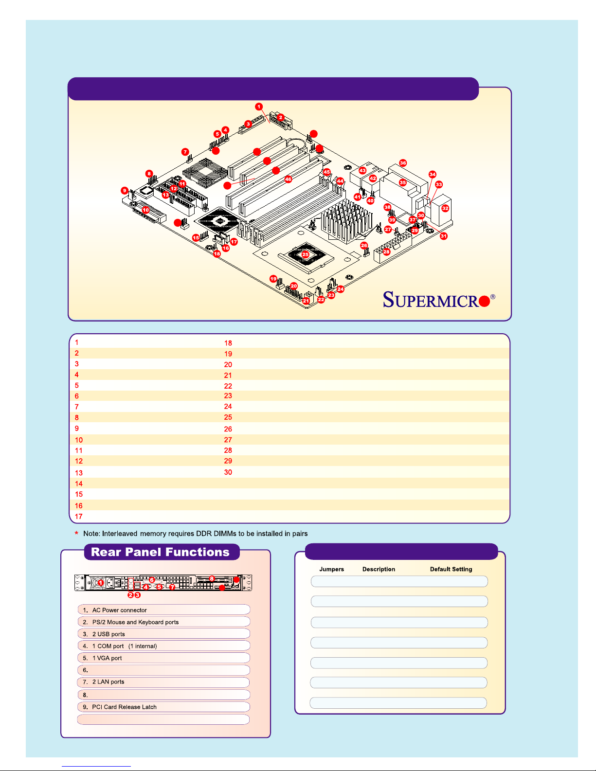
SuperServer 5013C-M8 Serverboard Components
51
6
52
14
49
48
47
50
P4SC8 serverboard
Ext. SCSI CH #B port
SCSI CH #B
J36: keylock enable/disable
J18: Speaker enable
J37: Serial ATA LED activity header
JPA3: SCSI enable/disable
USB 3/4 ports
Chassis Fan #3
SCSI CH #A
IDE #2
Floppy connector
IDE #1
Chassis fan #2
J16: infrared port
SATA 1 port
SATA 2 port
5013C-M8
Printer port
64-bit PCI-X 66MHz slot
10. External SCSI
JL1: chassis intrusion header
Chassis fan #4
JF1: front control panel header
J21: +12V 4-pin power connector
Chassis fan #1
J17: power LED
CPU fan
CPU 478 mPGA socket
JP8: Watchdog reset
J20: ATX power connector
JP20: system power force on
COM2
JPUSB: USB1/2 wake-up
JPWAKE: keyboard wake-up
31
Keyboard/mouse ports
32
USB 1/2 ports
33
COM1
34
9
10
35 Parallel port
36 VGA port
37 WOR: Wake-on-Ring
38, 39 JP1, JP2: CPU clock speed
40 JP3: OH fan force on
41 Overheat fan
42 Gigabit LAN #1
43 Gigabit LAN#2
44 Bank 0 (DIMM 0A & 0B)
45 Bank 1 (DIMM 1A & 1B)
46 PCI-X #1
47 PCI-X #2
48 PCI #1
49 PCI #2
50 JPL2: GLAN2 enable/disable
51 J33: VGA enable/disable
52 J15: System management bus
P4SC8 Quick Reference
J17 Power LED Closed (On)
JBT1 CMOS Clear Pad
J18 Speaker Pins 3-4 (Internal)
J33 VGA Enable/Disable Pins 1-2 (Enable)
J36 Keylock Enable/Disable Open (Disabled)
JP1, JP2 CPU Clock Speed Pins 1-2 (Auto)
JP3 OH Fan Force On Closed (On)
JP8 Watch Dog Reset Pins 1-2 (WD Reset)
JP20 Power Force On Open (Disabled)
JPA3 SCSI Enable/Disable Pins 1-2 (Enabled)
JPL2 GLAN2 Enable/Disable Pins 1-2 (Enabled)
JPUSB USB1/2 Wake Up En/Dis Pins 1-2 (Disabled)
JPWAKE Keyboard Wake-up Pins 1-2 (Disabled)
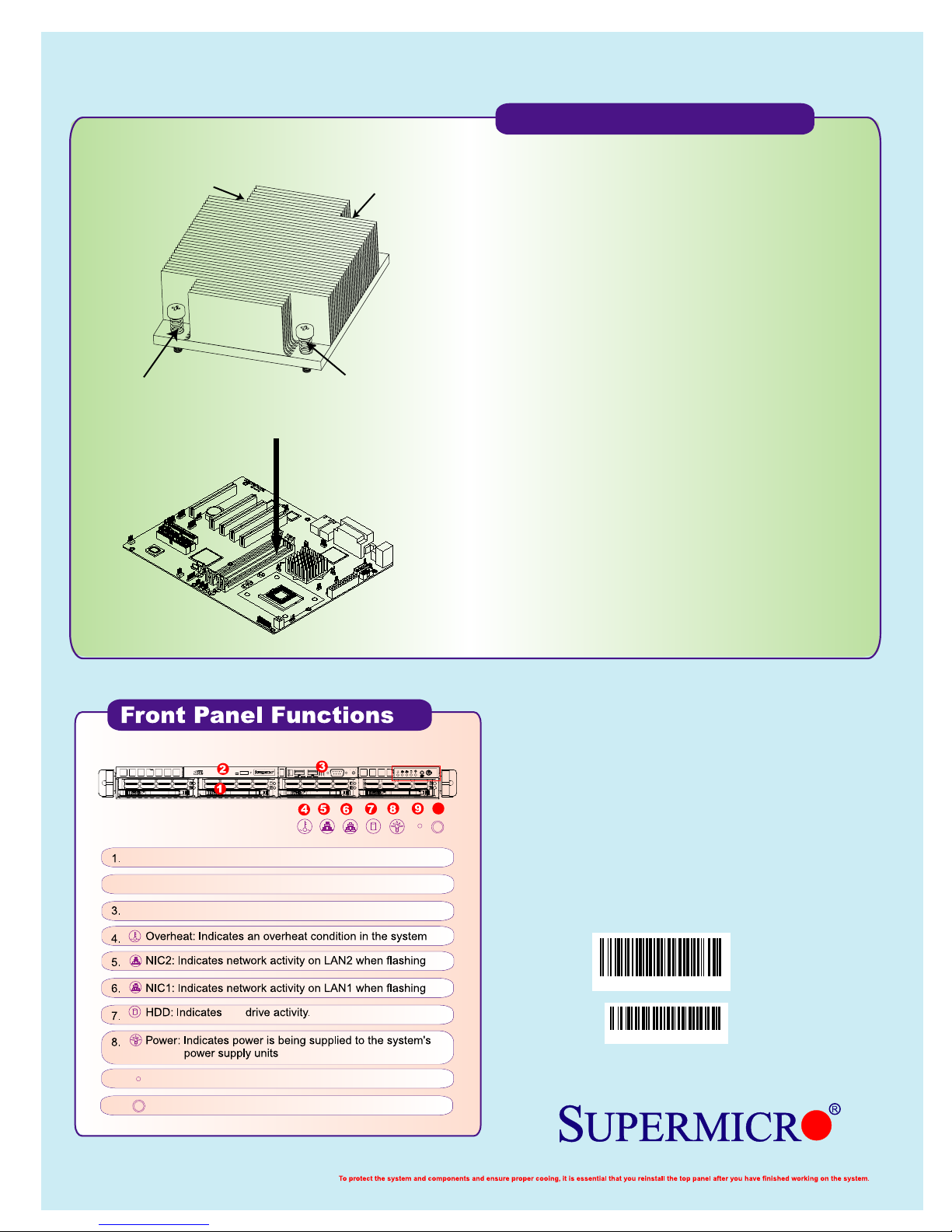
SNK-P0002
Heatsink Installation
No.1 Screw
No.3 Screw
No.4 Screw
No.2 Screw
Caution!
Do not apply any thermal grease to the heatsink; the
required amount of thermal grease has already been
applied.
1) Only those CPU heatsinks that are provided by Supermicro
should be used.
2) Do not apply any thermal grease to the heatsink - the required
amount has already been applied.
3) Place the heatsink on top of the CPU so that the four mounting
holes are aligned with those on the chassis.
4) Screw in two diagonal screws (ie. the #1 and #2 screws) until
just snug (do not fully tighten), then do the same with the
remaining two diagonal screws.
5) Finish by fully tightening all four screws.
5013C-M8
4 Hot-swap SCSI drive bays
2. CD-ROM drive
Front side 2 USB & 1 COM port
9. Reset button
10. Power button
10
LBL-0119
HD
REV 1.0
 Loading...