

Page 1

L2 / L3 Switches
Internet Protocol (IP)
Configuration Guide
Revision 1.0
Page 2

Supermicro L2/L3 Switches Configuration Guide
2
The information in this USER’S MANUAL has been carefully reviewed and is believed to be accurate. The vendor
assumes no responsibility for any inaccuracies that may be contained in this document, makes no commitment to
update or to keep current the information in this manual, or to notify any person organization of the updates.
Please Note: For the most up-to-date version of this manual, please see our web site at www.supermicro.com.
Super Micro Computer, Inc. (“Supermicro”) reserves the right to make changes to the product described in this
manual at any time and without notice. This product, including software, if any, and documentation may not, in
gf67cbbwhole or in part, be copied, photocopied, reproduced, translated or reduced to any medium or machine
without prior written consent.
IN NO EVENT WILL SUPERMICRO BE LIABLE FOR DIRECT, INDIRECT, SPECIAL, INCIDENTAL,SPECULATIVE OR
CONSEQUENTIAL DAMAGES ARISING FROM THE USE OR INABILITY TO USETHIS PRODUCT OR DOCUMENTATION,
EVEN IF ADVISED OF THE POSSIBILITY OF SUCHDAMAGES. IN PARTICULAR, SUPERMICRO SHALL NOT HAVE
LIABILITY FOR ANY HARDWARE,SOFTWARE, OR DATA STORED OR USED WITH THE PRODUCT, INCLUDING THE
COSTS OFREPAIRING, REPLACING, INTEGRATING, INSTALLING OR RECOVERING SUCH HARDWARE,SOFTWARE, OR
DATA.
Any disputes arising between manufacturer and customer shall be governed by the laws of Santa Clara County in
the State of California, USA. The State of California, County of Santa Clara shall be the exclusive venue for the
resolution of any such disputes. Super Micro's total liability for all claims will not exceed the price paid for the
hardware product.
FCC Statement: This equipment has been tested and found to comply with the limits for a Class A digital device
pursuant to Part 15 of the FCC Rules. These limits are designed to provide reasonable protection against harmful
interference when the equipment is operated in a commercial environment. This equipment generates, uses, and
can radiate radio frequency energy and, if not installed and used in accordance with the manufacturer’s instruction
manual, may cause harmful interference with radio communications. Operation of this equipment in a residential
area is likely to cause harmful interference, in which case you will be required to correct the interference at your
own expense.
California Best Management Practices Regulations for Perchlorate Materials: This Perchlorate warning applies only
to products containing CR (Manganese Dioxide) Lithium coin cells. Perchlorate Material-special handling may
apply. See http://www.dtsc.ca.gov/hazardouswaste/perchlorate/ for further details.
Manual Revision 1.0
Release Date: September 26, 2013
Unless you request and receive written permission from Super Micro Computer, Inc., you may not copy any part of
this document.
Information in this document is subject to change without notice. Other products and companies referred to
herein are trademarks or registered trademarks of their respective companies or mark holders.
Copyright © 2013 by Super Micro Computer, Inc.
All rights reserved.
Printed in the United States of America
Page 3

Supermicro L2/L3 Switches Configuration Guide
3
Contents
1 IP Configuration Guide .......................................................................................................................... 4
1.1 IP Overview ................................................................................................................................... 4
1.2 Layer 3 Interface ........................................................................................................................... 5
1.2.1 Physical L3 Interface ............................................................................................................. 5
1.2.2 Layer 3 VLAN Interface .......................................................................................................... 7
1.2.3 Loopback Interface ................................................................................................................ 9
1.3 Inter-VLAN Routing ..................................................................................................................... 10
1.4 Static Route ................................................................................................................................. 12
1.5 ARP .............................................................................................................................................. 14
1.6 DHCP ........................................................................................................................................... 16
1.6.1 DHCP Server ........................................................................................................................ 17
1.6.2 DHCP Client ......................................................................................................................... 25
1.6.3 DHCP Relay Agent ............................................................................................................... 27
1.7 VRRP ............................................................................................................................................ 29
Page 4

Supermicro L2/L3 Switches Configuration Guide
4
1 IP Configuration Guide
This document describes the system features supported in Supermicro Layer 2 / Layer 3 switch products.
This document covers the system configurations for the below listed Supermicro switch products.
Top of Rack Switches
• SSE-G24-TG4
• SSE-G48-TG4
• SSE-X24S
• SSE-X3348S
• SBM-GEM-X2C
• SBM-GEM-X2C+
• SBM-GEM-X3S+
• SBM-XEM-X10SM
Blade Switches
• SSE-X3348T
The majority of this document applies to the above listed Supermicro switch products. In any particular
sub section however, the contents might vary across these product models. In those sections the
differences are clearly identified with reference to a particular model(s). If any particular model is not
referenced, the reader can safely assume that the content is applicable to all the above listed models.
Throughout this document, the common term “switch” refers to any of the above listed
Supermicro switch models unless a particular model is noted.
1.1 IP Overview
Internet Protocol (IP), the foundation of the IP protocol suite, is a packet-based protocol used for the
exchange of data over computer networks. IP is a network layer that contains addressing and control
information to allow routing of data packets. IP handles addressing, fragmentation, reassembly, and
protocol de-multiplexing.
Supermicro switches support both TCP and UDP at the transport layer for maximum flexibility in
services.
• Transmission Control Protocol (TCP) is a connection-oriented protocol built upon the IP layer.
TCP specifies the format of data and acknowledgments used in the transfer of data and also the
Page 5

Supermicro L2/L3 Switches Configuration Guide
5
procedures used to ensure that the data arrives in correct order. With TCP, multiple applications
on a system can communicate concurrently as it handles all de-multiplexing of the incoming
traffic among the application programs.
• With UDP, applications can send messages(also called datagrams) to other hosts on an IP
network without prior setup of transmission channels or data paths. UDP is suitable when error
checking and correction is either not necessary or performed in the application, avoiding the
overhead of such processing at the network interface level.
The following features of IP implementation in Supermicro switches are covered in this document.
• Layer3 Interface
• Inter-VLAN routing
• Static Route
• ARP
• DHCP
• VRRP
1.2 Layer 3 Interface
The network layer, or Layer 3,handles the routing of data in packets acrosslogical internetwork paths.
The data link layer, or Layer 2,contains protocols that control the physical layer (Layer 1) and data
framing for transmission on the physical medium. The Layer 2 function of filtering and forwarding data
in frames between two segments on a LAN is known as bridging.
Supermicro switches support three types of Layer 3 interfaces.
• The Layer 3VLAN Interface combines the functionality of routing and bridging.
• The physical Layer 3 interface allows the switch to be configured like a traditional router. It is
also referred as a Routed Interface.
• The Loopback Interface is a logical interface that is “always up”. It is not tied to any physical
interface therefore it does not go down unless it is administratively shut down.
The Layer3 interface is used to:
• Allow traffic to be routed between VLANs.
• Provide Layer 3 IP connectivity to the switch.
1.2.1 Physical L3 Interface
The physical Layer 3 interfaces support functionalities similar to a traditional router. Routed ports are
physical ports on the switch that act like a router interface with an IP address configured; they do not
belong to any VLAN.
Supermicro switches support Secondary IP addresses, which are used when the same physical segment
of the switch interface that is connected serves multiple logical networks.
Page 6

Supermicro L2/L3 Switches Configuration Guide
6
Step 1
configure terminal
Enters the configuration mode
Step 2
interface
<
interface
-
type
><
interface
-id>
Enters
the interface configuration
Step 3
no switchport
Configure
s the
router port
Step 4
ip address [<ip
-
address> | <ip
-
address>/prefix
-
Configure
s the
IP address.
Follow the steps below to configure a Physical Layer3 Interface.
Step Command Description
or
interface range <interface-type><interface-id> ….
mode.
1.2.2
interface-type – may be any of the
following:
gigabitethernet – gi
extreme-ethernet – ex
qx-ethernet – qx
1.2.3
interface-id is in slot/port format for all
physical interfaces.
To configure multiple interfaces, use
the “interface range …” command. To
provide a range use a hyphen (-)
between the start and end interface
numbers. E.g.: int range gi 0/1-10
length] [<subnet-mask>] [secondary]
1.2.4
To provide multiple interfaces or
ranges, separate with a comma (,).
E.g.: int range gi 0/1-10, gi 0/20
1.2.5
If multiple interfaces are provided, the
next step will perform the particular
configuration on all these interfaces.
ip-address – A valid IPv4 address.
ip-address/prefix-length - A valid IPv4
Page 7

Supermicro L2/L3 Switches Configuration Guide
7
a
ddress with a prefix length of value 1
-
Step 5
end Exi
ts the configuration mode.
Step 6
show
ip interface
Displays the
Layer 3
interface
IP Routing is enabled by default in Supermicro switches.
32.
subnet-mask – A valid IP subnet mask.
1.2.6
Secondary - Assigns multiple IP
addresses to network interfaces.
1.2.7
information.
The “switchport” command deletes the Physical Layer 3 interface and the interface is reset
as a Layer2 interface.
The example below shows the commands used to configure a Physical Layer3 Interface.
SMIS# configure terminal
SMIS(config)# interface Gi 0/22
SMIS(config-if)# no switchport
SMIS(config-if)# ip address 20.20.20.1 255.255.255.0
SMIS(config-if)# end
SMIS# show ip interface
Gi0/22 is up, line protocol is up
Internet address is 20.20.20.1/24
Broadcast address is20.20.20.255
mgmt is up, line protocol is down
Internet address is 192.168.100.102/24
Broadcast address is192.168.100.255
Gateway 0.0.0.0
1.2.8 Layer 3 VLAN Interface
VLANs typically operate at Layer 2. When aLayer2 VLAN is configured with an IP address, it behaves as a
logical Layer 3 VLAN interface. A L3 VLAN interface provides logical routing interfaces to VLANs on Layer
Page 8

Supermicro L2/L3 Switches Configuration Guide
8
Step 1
configure terminal
Enters the co
nfiguration mode
Step 2
Create a Layer 2 VLAN and add all required ports.
For details on configuring
a
Layer 2
Step 3
interface
vlan<vlan
-
id (1
-
4069)>
Entersthe
interface configuration mode
Step 4
ip address [<ip
-
address> | <ip
-
address>/prefix
-
Configure
s the
IP address.
Step
5 end Exits the configuration mode.
Step
6 show
ip interface
Displays the Layer 3 interface
The “
no ip address [<ip_addr>]
”
command
deletes the
L
ayer 3 VLAN interface and
resets
it
2 switches.It is also called aSwitch Virtual Interface (SVI )and handles processing for all the packets
associated with that VLAN.
Follow the steps below to configure a Logical Layer3 Interface.
Step Command Description
VLAN, refer to the ‘VLAN Config. guide’
at www.supermicro.com
to specify the interface to be
configured as a Layer 3 interface.
length] [<subnet-mask>] [secondary]
ip-address – A valid IPv4 address.
ip-address/prefix-length - A valid IPv4
address with a prefix length of value 1-
32.
subnet-mask – A valid IP subnet mask.
Secondary - Assigns multiple IP
addresses to network interfaces.
information.
as a Layer2 VLAN.
The example below shows the commands used to configure a Logical Layer3 interface.
SMIS# configure terminal
SMIS(config)# vlan 10
SMIS(config-vlan)# ports Gi 0/22 untagged
SMIS(config-vlan)# exit
SMIS(config)# interface vlan 10
SMIS(config-if)#ip address 10.10.10.1 255.255.255.0
SMIS(config-if)# end
Page 9

Supermicro L2/L3 Switches Configuration Guide
9
Step 1
configure terminal
Enters the configuration mode
Step
2 interface
loopback <interface
-
id (1
-
100)>
Enters
interface configuration mode
to
Step
3 ip address [<ip
-
address> | <ip
-
address>/prefix
-
Configure IP address.
Step 4
no shutdown
Enable the
l
oopback interface
S
tep 5
end Exits the configuration mode.
Step
6 show ip interface
Displays the
Layer 3 interface
SMIS# show ip interface
mgmt is up, line protocol is down
Internet address is 192.168.100.102/24
Broadcast address is 192.168.100.255
Gateway 0.0.0.0
vlan10 is up, line protocol is up
Internet address is 10.10.10.1/24
Broadcast address is 10.10.10.255
1.2.9 Loopback Interface
Supermicro switches support a loopback interface, which is a virtual interface and is not connected to
any other device. Loopback interfaces are very useful since they will never go down unless the entire
router goes down. This is useful for managing routers because there will always be at least one active
interface on the routers: the loopback interface.
Follow the steps below to configure loopback interface.
Step Command Description
specify the interface to be configured
as a Layer 3 interface.
length] [<subnet-mask>]
ip-address – A valid IPv4 address.
ip-address/prefix-length - A valid IPv4
address with a prefix length of value 1-
32.
subnet-mask – A valid IP subnet mask.
NOTE: Subnet mask should be 32-bit for
loopback interface.
show interface loopback <1-100>
configuration.
Display the loopback interface
Page 10

Supermicro L2/L3 Switches Configuration Guide
10
configuration.
IP Routing is not supported on
l
oopback
i
nterfaces.
The “nointerface loopback <interface-id (1-100)>” command deletes the loopback
interface.
SMIS# configure terminal
SMIS(config)# interface loopback 1
SMIS(config-if)# ip address 100.1.1.1/32
SMIS(config-if)# no shutdown
SMIS(config-if)# end
SMIS# show interface loopback 1
Interface Status Protocol Description
--------- ------ -------- ----------loopback1upup
SMIS# show ip interface
mgmt is up, line protocol is down
Internet address is 192.168.100.102/24
Broadcast address is 192.168.100.255
Gateway 0.0.0.0
loopback1 is up, line protocol is up
Internet address is 100.1.1.1/32
Broadcast address is 100.1.1.1
1.3 Inter-VLAN Routing
VLANs enable splitting traffic across several manageable broadcast domains. Devices within a VLAN can
communicate with one another without requiring routing. Whenever hosts in one VLAN need to
communicate with hosts in another VLAN, the traffic must be routed between them. This is known as
Inter-VLAN Routing.
Supermicro switches use application-specific integrated circuits (ASICs), which are hardware chips that
can route traffic at very high speeds. These ASICs are installed on the switching engine of a Layer 3
switch, which traditionally switches frames at Layer 2. The ASICs allow the switching engine to also
switch frames that contain packets sent between different VLANs. Each ASIC is programmed with the
information required to route traffic from one VLAN to another, without having to pass the traffic
through the CPU of the routing engine.
Advantages of Inter-VLAN routing in L3 switches:
Page 11
Supermicro L2/L3 Switches Configuration Guide
11
To WAN via Router
• Layer 3 switches are much more cost effective than routers for delivering high-speed inter-VLAN
routing.
• Layer 3 switches are enhanced Layer 2 switches, and therefore have the same high port
densities as Layer 2 switches. Routers on the other hand typically have a much lower port
density.
• Layer 3 switches can be configured to operate as a normal Layer 2 switch or Layer 3 switch as
required.
Application of Inter-VLAN routing:
The network can be divided based on the group or function of itsdevices. For example, an engineering
department VLAN would only have devices associated with the engineering department, while an HR
VLAN would only have HR related devices. With Inter-VLAN routing, the devices in each VLAN can talk to
one another without all the devices being in the same broadcast domain.
VLAN 300
VLAN 100
VLAN 200
Layer3
Figure IP-1: Inter-VLAN Routing
Follow the steps below to configure Inter-VLAN routing.
1. Create two Layer 3 interface VLANs.
2. Configure an IP address for both interfaces of these Layer 3 VLANs.
3. Execute show ip route to check if the VLAN routes specified by VLAN IP address are displayed as
connected routes. The routing table has an entry for each VLAN interface subnet, therefore,
devices in VLAN 10 can communicate with devices in VLAN 20 and vice versa.
The example below shows the commands used to configure Inter-VLAN routing.
SMIS# configure terminal
Page 12

Supermicro L2/L3 Switches Configuration Guide
12
SMIS(config)# vlan 10
SMIS(config-vlan)# ports Gi 0/21 untagged
SMIS(config-vlan)# exit
SMIS(config)# interface vlan 10
SMIS(config-if)#ip address 10.10.10.1 255.255.255.0
SMIS(config-if)# exit
SMIS(config)# vlan 20
SMIS(config-vlan)# ports Gi 0/22 untagged
SMIS(config-vlan)# exit
SMIS(config)# interface vlan 20
SMIS(config-if)# ip address 20.20.20.1255.255.255.0
SMIS(config-if)# end
SMIS# show ip interface
mgmt is up, line protocol is down
Internet address is 192.168.100.102/24
Broadcast address is 192.168.100.255
Gateway 0.0.0.0
vlan10 is up, line protocol is up
Internet address is 10.10.10.1/24
Broadcast address is 10.10.10.255
vlan20 is up, line protocol is up
Internet address is 20.20.20.1/8
Broadcast address is 20.255.255.255
SMIS# show ip route
C 10.10.10.0/24 is directly connected, vlan10
C 20.0.0.0/8 is directly connected, vlan20
C 192.168.100.0/24 is directly connected, mgmt
1.4 Static Route
A static route defines an explicit path between two routers. Manual reconfiguration of static routes is
required whenever network changes occur. Static routes use less bandwidth than dynamic routes. No
CPU cycles are used to calculate and analyze routing updates.
Routers forward packets using either route information from manually configured route table entries or
by using the route information calculated with dynamic routing algorithms.
Use of Static Routes:
Page 13

Supermicro L2/L3 Switches Configuration Guide
13
Step 1
configure terminal
Enters the configuration mode
Step 2
ip route <prefix><mask> {<next
-
hop> | Vlan<vlan
-
Configure
s the
static route. The VLAN id
Step 3
end Exits the configuration mode.
Step 4
show ip route [ { <ip
-
address> [<mask>] | bgp |
Displays the
route information
W
hen an interface goes down, static routes through that interface are removed
from the IP
• Static routes can be used in environments where network traffic is predictable and the network
design is simple.
• Static routes are also useful for specifying a gateway of last resort (a default router to which all
non-routable packets are sent).
Follow the steps below to configure a static route.
Step Command Description
id (1-4069)> | <interface-type><interface-id> |
null0 } [<distance (1-255)>] [ private ]
and interface for this static route.
Prefix –The destination network IP
address the route leads to.
Mask – A valid IP subnet mask
1.4.1
Next-hop – specifies the next-hop IP
address.
Null - Specifies a null interface
1.4.2
Distance – Specifies the administrative
distance in the range of 1 to 255. The
default is 1.
Private- Specifies whether this route
can be shared with other routes when
RIP is enabled.
connected | ospf | rip | static | summary } ]
routing table.
When the next hop for the address is unreachable, the static route is removed from the IP
routing table.
The “no ip route <prefix><mask> { <next-hop> | Vlan<vlan-id(1-4069)> | <interface
-type><interface-id> | null0 } [private]” command deletes the static route.
Page 14

Supermicro L2/L3 Switches Configuration Guide
14
The example below shows the commands used to configure a static route.
SMIS# configure terminal
SMIS(config)# vlan 10
SMIS(config-vlan)# ports Gi 0/21 untagged
SMIS(config-vlan)# exit
SMIS(config)# interface vlan 10
SMIS(config-if)# ip address 10.10.10.1
SMIS(config-if)# exit
SMIS(config)# ip route 200.200.200.0 255.255.255.0 10.10.10.2
SMIS(config)# end
SMIS# show ip route static
S 200.200.200.0/24 [1] via 10.10.10.2
1.5 ARP
The Address Resolution Protocol (ARP) feature finds the hardware address, also known as the Media
Access Control (MAC) address, of a host from its known IP address. This mapping of MAC addresses to IP
addresses is stored in a table called the ARP cache.
ARP is part of all Supermicro switches systems that run IP. Though Supermicro switches are Layer 3
switches that forward packets based on IP address, ARP is required for certain cases like default
gateways or for pinging within the same subnet.
1.5.1.1 Cache Timeout
The ARP cache can contain both dynamic (learned) entries and static (user-configured) entries. Dynamic
ARP entries are created in the ARP cache when the Layer 3 switch learns a device’s MAC address from
an ARP request or from the ARP reply from a device. ARP entries are refreshed periodically, otherwise
they will time out and be deleted from the ARP cache.
1.5.1.2 ARP Request Retry
ARP requests can be resent by a device before confirming the host as unreachable. The number of times
ARP requests can be retransmitted is user configurable in Supermicro switches.
1.5.1.3 Static ARP
For hosts that do not support dynamic Address Resolution Protocol(ARP), static entries can be added by
defining the static mapping between an IP address (a 32-bit address) and a Media Access Control (MAC)
address (a 48-bit address). Static ARP entries in the ARP cache never time out. The entries remain in the
ARP table until they are removed by the user configuration.
Page 15

Supermicro L2/L3 Switches Configuration Guide
15
ARP request retr
ies 3
ARP cache timeout
300
Static ARP entrie
s None
Step 1
configure terminal
Enters the configuration mode
Step 2
arp timeout <seconds (30
-
86400)>
(Optional)
Sets the length of time, in
Step 3
arp<ip address><hardware address> {Vlan<vlan
-
(Optional)
Globally associates an IP
Step
4 iparp max
-
retries <value (2
-
10)>
(Optional)
Sets the maximum number
Step
5 end Exits the configuration mode.
Step
6 show iparp
Displays the
ARP table
entries.
Defaults
Parameter Default Value
Follow the steps below to configure the ARP.
Step Command Description
seconds, an Address Resolution
Protocol (ARP) cache entry stays in the
cache. The range is 30-86400 seconds.
Note: If there are frequent changes to
cache entries in a network ,a shorter
ARP timeout is recommended.
id(1-4069)> | <interface-type><interface-id> |
Linuxvlan<interface-name>| Cpu0}
show iparp summary
show iparp information
address with a MAC address in the ARP
cache.
ip-address—IP address in four-part
dotted decimal format corresponding
to the local data-link address.
hardware-address—Local data-link
address (a 48-bit address).
Linuxvlan - Interface name of a Linux
VLAN interface.
Cpu0 - Out-of-band management
interface
of ARP request retries in the range of 2-
10.
Displays a summary of the ARP table,
including dynamic and static entries.
Displays the ARP configuration details.
Page 16

Supermicro L2/L3 Switches Configuration Guide
16
These commands delete values or reset to default values, as applicable:
no arp timeout
no arp<ip address>
no iparp max-retries
The example below shows the commands used to configure the ARP.
SMIS# configure terminal
SMIS(config)# arp timeout 800
SMIS(config)# iparp max-retries 10
SMIS(config)# arp 10.0.0.0 48:2C:6A:1E:59:3D vlan 1
SMIS(config)# end
SMIS# show iparp
Address Hardware Address Type Interface Mapping
------- ---------------- ---- --------- -------
10.0.0.0 48:2c:6a:1e:59:3d ARPA vlan1 Static
SMIS# show iparp summary
1 IP ARP entries, with 0 of them incomplete
SMIS# show iparp information
ARP Configurations:
-------------------
Maximum number of ARP request retries is 10
ARP cache timeout is 800 seconds
1.6 DHCP
The Dynamic Host Configuration Protocol (DHCP) is based on the Bootstrap Protocol (BOOTP), which can
automatically allocate reusable network addresses and configuration options to Internet hosts. DHCP is
built on a client/server model where designated DHCP servers allocate network addresses and deliver
configuration parameters to DHCP clients.
When a DHCP client requests an IP address from a DHCP server, the client sends a DHCPDISCOVER
broadcast message to locate a DHCP server. A relay agent forwards the packets between the DHCP
client and the server. A DHCP server offers configuration parameters (such as an IP address, MAC
address, domain name, and a lease for the IP address) to the client in a DHCPOFFER unicast message.
Page 17

Supermicro L2/L3 Switches Configuration Guide
17
Supermicro switches support Dynamic Host Configuration Protocol (DHCP) server, DHCP client and DHCP
relay agent functionality.
1.6.1 DHCP Server
The DHCP server implementation in Supermicro switches maintains a database of available IP addresses
and configuration information. When the DHCP server receives a request from a DHCP client, the DHCP
server determines the network to which the DHCP client is connected. The DHCP server then allocates
an IP address or prefix that is appropriate for the client. DHCP servers typically grant IP addresses to
clients only for a limited interval. DHCP clients must either renew their IP address before that interval
has expired or must stop using the address once the interval has expired. The DHCP server can also be
configured to assign additional parameters like default routers, the IP address of the Domain Name
System (DNS) server,etc. The DHCP server can accept broadcasts from locally attached LAN segments or
from DHCP requests that have been forwarded by other DHCP relay agents within the network.
DHCP
Figure IP-2: DHCP Server
DHCP Discover
DHCP Offer
DHCP Request
DHCP Ack
DHCP
Client
1.6.1.1 DHCP Address Pool
The DHCP server in Supermicro switches accepts requests for address assignment and renewals. It
assigns the addresses from predefined groups of addresses contained within DHCP address pools. These
address pools can also be configured to supply additional information to the requesting client such as
the IP address of the DNS server, the default router, and other configuration parameters.
1.6.1.2 Additional Parameter - Default Router & DNS
The DHCP server can be configured to assign additional parameters to the DHCP clients such as the IP
address of the Domain Name System (DNS) server and the default router.
Page 18

Supermicro L2/L3 Switches Configuration Guide
18
DHCP server
status
Disabled
DHCP
s
erver IP address
None
The default route IP address should be on the same subnet as the client. When a DHCP client requests
an IP address, the DHCP server accesses the default router list to select another router that the DHCP
client is to use as the first hop for forwarding messages.
1.6.1.3 Excluding IP Addresses
By default, the DHCP Server assumes all IP addresses in the configured DHCP address pool are available
for assigning to DHCP clients. If a particular address or range of addresses should not be assigned to
DHCP clients, users can configure these as excluded IP addresses.
1.6.1.4 Utilization Threshold
A DHCP address pool has a threshold associated with it. If a pool’s outstanding addresses exceed the
high utilization threshold and SNMP trap signaling is enabled, SNMP is notified.
1.6.1.5 Lease
DHCP supports three mechanisms for IP address allocation:
• Automatic allocation: the DHCP server assigns a permanent IP address to a client.
• Dynamic allocation: the DHCP server assigns an IP address to a client from the address pool for either a
limited period of time called a lease or until the client relinquishes the address.
• Manual allocation: the network administrator assigns an IP address to a client and DHCP is used simply
to convey the assigned address to the client.
1.6.1.6 Options and Sub-options
Configuration parameters and control information are available inthe options field of the DHCP
message. This can be used when additional information need not be stored in DHCP client, rather it can
be transmitted by the DHCP server to the client.
Some DHCP clients send a client identifier (DHCP option 61) in the DHCP packet to the DHCP server.
Configuring manual bindings for such clients is done in the client-identifier DHCP pool configuration. To
configure manual bindings for clients who do not send a client identifier option, configure the hardwareaddress DHCP pool configuration.
1.6.1.7 Boot File
The boot file is used to store the boot image for the client. The boot image is generally the operating
system the Dynamic Host Configuration Protocol (DHCP)client uses to load.
1.6.1.8 DHCP Ping
The DHCP server pings a pool address twice before assigning a particular address to a requesting client.
If the ping is unanswered, the DHCP server assumes that the address is not in use and assigns the
address to the requesting client.
1.6.1.9 DHCP Server Configuration
Defaults
Parameter Default Value
Page 19

Supermicro L2/L3 Switches Configuration Guide
19
DHCP pool index
None
DHCP network IP
None
Excluded
address
None
Domain
n
ame None
DNS server
None
NetBIOS name server
None
NetBIOS node type
None
DHCP option
None
Lease
3600
Utilization
t
hreshold
75
Default router
None
Hardware
a
ddress
None
Client ID
None
Bootfile
None
Next
-
server
None
DHC
P ping
None
Offer reuse
5
Step 1
configure terminal
Enters the configuration mode.
Step 2
service dhcp
-
server
Enable
the
DHCP server.
Step 3
end Exits the configuration mode.
Step 4
show ipdhcp server information
Displays the DHCP server configuration
The
DHCP
r
elay must be disabled before enabling
the
DHCP
s
erver.
Step 1
configure terminal
Enters the configuration mode.
Step 2
ipdhcp pool <index (1
-
214
7483647)>
Creates a name for the DHCP server
1.6.1.9.1 Enabling a DHCP Server
The DHCP server is disabled by default in Supermicro switches. Follow the steps below to enable a DHCP
server.
Step Command Description
details.
The ‘noservice dhcp-server’ command disables the DHCP server.
1.6.1.9.2 Configuring the DHCPPool
Follow the steps below to configure the DHCP server pool.
Step Command Description
Page 20

Supermicro L2/L3 Switches Configuration Guide
20
address pool and enters
the
DHCP poo
l
Step 3
network <network
-
IP> [ { <mask> | / <prefix
-
Specifies the subnet network number
Step 4
excluded
-
address <low
-
address><
high-
address >
(Optional)
Specif
ies the range of
IP
Step 5
domain
-
name <domain (63)>
(Optional)
Specifies the domain name
Step 6
dns-server <ip address>
(Optional) Specifies the IP address of a
Step 7
netbios
-
name
-
server <ip address>
(Optional) Specifies the NetBIOS WINS
Step 8
netbios
-
node
-
type { <0
-
FF> | b
-
node | h
-
node |
(Optional) Specifies the NetBIOS node
Step 9
option <code (1
-
2147483647
)> { ascii<string> |
(Optional) Configures
the
DHCP server
configuration mode.
length (1-31)> } ] [<start-ip> [<end-ip>]]
and mask of the DHCP address pool.
Network-ip – A valid IPv4 address.
prefix-length - A valid IPv4 address with
a prefix length value of 1-32.
mask – A valid IP subnet mask.
start-ip and end-ip specifies the address
pool range
addresses that the DHCP server must
not assign to DHCP clients in the range
of low-address to high-address.
for the client.
DNS server that is available to a DHCP
client.
server that is available to a Microsoft
DHCP client.
m-node | p-node }
hex <Hex String> | ip<address> }
type for a Microsoft DHCP client.
1.6.2
b-node – Broadcast node
h-node – Hybrid node
m-node – Mixed node
p-node – Peer to peer node
options.
1.6.3
Configurable DHCP options with their
Page 21

Supermicro L2/L3 Switches Configuration Guide
21
corresponding
length values
:
Step 10
lease { <days (0
-
365)> [<hours (0
-
23)> [<minutes
(Optional) Specifies the duration of the
Step 11
utilization threshold { <integer (0
-
100)> }
(Optional) Configures the utilization
Step 12
default
-
router <ip address>
(Optional) Specifies the IP address of
Step 13
host hardw
are-type <type (1
-
2147483647)>
(Optional)
S
pecif
ies the hardware MAC
- Options 19, 20, 27, 29, 30, 31, 34, 36,
39, 46 must have a length of 1
- Options 12, 14, 15, 17, 18, 40, 43, 47,
64, 66, 67 must have a length >1
- Option 16 must have minimum length
of 4 and the value must be an IP
address
- Option 25 can have a length of 2 or
2*n
- Option 68 must have length of 4 and
the value must be an IP address
(0-59)>]] | infinite }
- Options 1-11, 41, 42, 44, 45, 48, 49,
65, 69, 70-76 must have a length of 4
and the value must be an IP address
- Options 21, 33 must have a minimum
length as 8 or 8*n
-Options 0, 255, 50-60 are nonconfigurable options
lease. The “infinite” keyword specifies
that the duration of the lease is
unlimited.
mark of the current address poolsize.
the default router for a DHCP client.
client-identifier <mac-address> option <code (1-
2147483647)> { ascii<string> | hex <Hex String> |
ip<address> }
address of the DHCP client.
1.6.4
Page 22

Supermicro L2/L3 Switches Configuration Guide
22
mac-address
-
Specifies
the
MAC
Step 14
end Exits the configuration mode.
Step 15
show
ip
dhcp server pools
Displays the DHCP pool configuration.
The “
no ipdhcp pool <index (1
-
2147483647)>
”
command
deletes the DHCP pool
address of a DHCP client in dotted
hexadecimal notation.
1.6.5
string - ASCII-format representation of
a MAC address
1.6.6
address - Specifies the IP address and
network mask for a manual binding to a
DHCP client.
configuration.
These commands delete values or reset to default values, as applicable:
no network
no excluded-address <low-address> [<high-address>]
no domain-name
no dns-server
no netbios-name-server
no netbios-node-type
no default-router
no option <code (1-2147483647)>
no lease
no utilization threshold
no host hardware-type <host-hardware-type (1-2147483647)> client-identifier <clientmac-address> option <code (1-2147483647)>
1.6.6.1.1 Configuring Other Parameters
Follow the steps below to configure the DHCP server parameters.
Step Command Description
Page 23

Supermicro L2/L3 Switches Configuration Guide
23
Step 1
configure terminal
Enters the configuration mode
.
Step
2 ipd
hcpbootfile<bootfile (63)>
(Optional) Specifies the name of the
Step
3 ipdhcp next
-
server <ip address>
(Optional) Configures the next server in
Step
4 ipdhcp option <code (1
-
2147483
647)> {
This option can be used to configure
Step
5 ipdhcp { ping packets | server offer
-
reuse
(Optional)
Specif
ies that the
DHCP
Step
6 end Exits the configuration mode.
Step
7 show ipdhcp server information
Displays the
DHCP server configuration
These commands delete values or reset
s the
default values, as applicable:
default boot image for a DHCP client.
the boot process of a DHCP client.
ascii<string> | hex <Hex String> | ip
the DHCP options for all pools.
<address> }
<timeout (1-120)> }
server should ping a pool address
before assigning it.
Server offer-reuse - Specifies the
maximum timeframe after which an
offered IP address can be returned to
the pool of free addresses.
show ipdhcp server statistics
details.
Displays DHCP packet statistics.
no ipdhcpbootfile
no ipdhcp next-server
no ipdhcp option <code (1-2147483647)>
no ipdhcp { ping packets | server offer-reuse | binding <ip address> }
The example below shows the commands used to configure DHCP Server.
SMIS# configure terminal
SMIS(config)# service dhcp-server
SMIS(config)# ipdhcp server 100.100.100.1
SMIS(config)# ipdhcp pool 1
SMIS(dhcp-config)# network 200.200.0.0 255.255.0.0
SMIS(dhcp-config)# excluded-address 200.200.20.20 200.200.20.30
SMIS(dhcp-config)# dns-server 10.10.10.1
SMIS(dhcp-config)# domain-name supermicro.com
SMIS(dhcp-config)# netbios-name-server 172.16.1.3
SMIS(dhcp-config)# netbios-node-type h-node
SMIS(dhcp-config)# option 19 hex 1
Page 24

Supermicro L2/L3 Switches Configuration Guide
24
SMIS(dhcp-config)# lease infinite
SMIS(dhcp-config)# utilization threshold 50
SMIS(dhcp-config)# host hardware-type 1 client-identifier 00:A0:23:C9:12:FF option 10 IP 10.10.10.1
SMIS(dhcp-config)# default-router 192.168.1.10
SMIS(dhcp-config)# exit
SMIS(config)#ipdhcpbootfileabcboot
SMIS(config)# ipdhcp next-server 172.17.10.3
SMIS(config)# ipdhcp ping packets
SMIS(config)# end
SMIS# show ipdhcp server information
DHCP server status: Enabled
Send ping packets: Enabled
Debug level: None
Server address reuse timeout: 5 secs
Next server address: 172.17.10.3
Boot file name: abcboot
SMIS# show ipdhcp server pools
Pool Id: 1
------------------------------------------Subnet: 200.200.0.0
Subnet mask: 255.255.0.0
Lease time: 2147483647 secs
Utilization threshold: 50%
Start Ip: 200.200.0.1
End Ip: 200.200.255.255
Exclude address start IP: 200.200.20.20
Exclude address end IP: 200.200.20.30
Subnet Options
-------------Code: 1, Value: 255.255.0.0
Code: 3, Value: 192.168.1.10
Code: 6, Value: 10.10.10.1
Code: 15, Value: supermicro.com
Code: 19, Value: 1
Code: 44, Value: 172.16.1.3
Code: 46, Value: 8
Host Options
------------
Page 25

Supermicro L2/L3 Switches Configuration Guide
25
Hardware type: 1
Client identifier: 00:a0:23:c9:12:ff
Code: 10, Value: 10.10.10.1
SMIS# show ipdhcp server statistics
Address pools: 1
Message Received
------- -------DHCPDISCOVER 0
DHCPREQUEST 0
DHCPDECLINE 0
DHCPRELEASE 0
DHCPINFORM 0
Message Sent
------- ---DHCPOFFER 0
DHCPACK 0
DHCPNAK 0
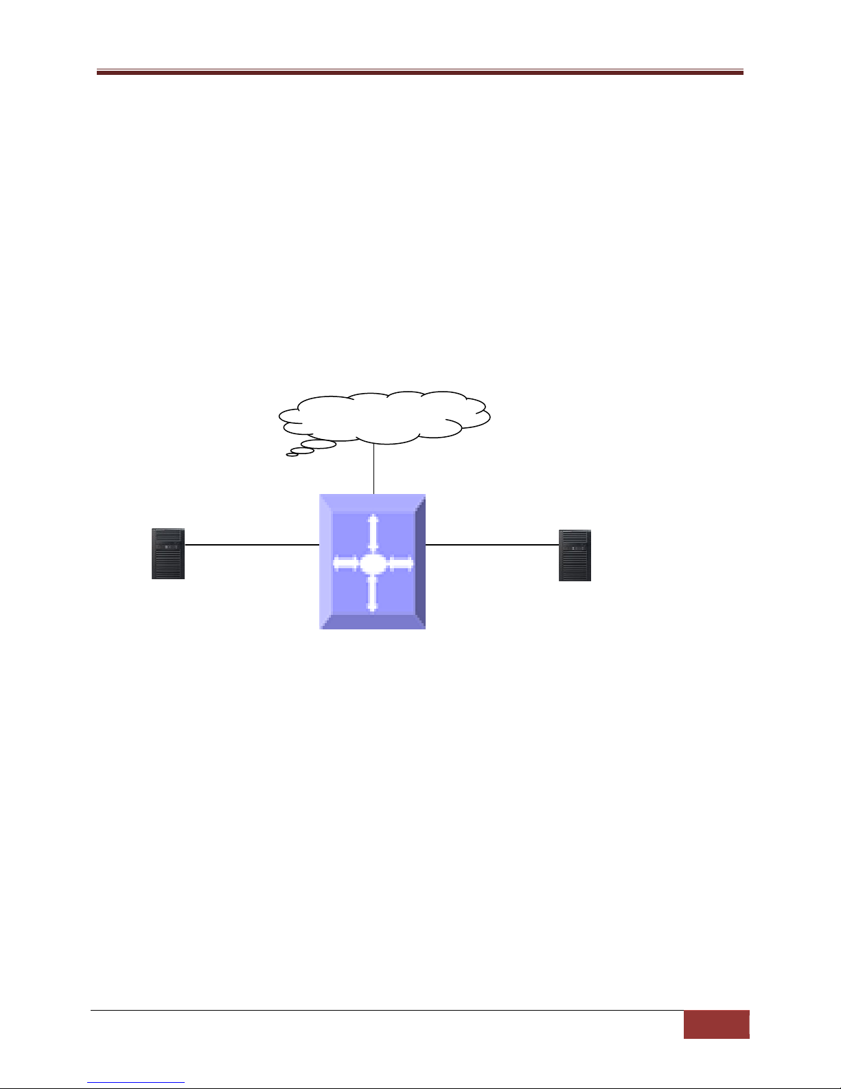
1.6.7 DHCP Client
Supermicro switches can function as a Dynamic Host Configuration Protocol (DHCP) client to obtain
configuration parameters such as an IP address from the DHCP server.
DHCP
Figure IP-3: DHCP Client
1.6.7.1 Release Client
The release dhcpcommand starts the process to immediately release a DHCP lease for the specified
interface. After the lease is released, the interface address is de-configured.
DHCP Discover
DHCP Offer
DHCP Request
DHCP Ack
DHCP
Server
Page 26

Supermicro L2/L3 Switches Configuration Guide
26
Step 1
configure
terminal
Enters the configuration mode
Step 2
interface
vlan<vlan
-
id (1
-
4069)>
|
interface
E
nters
the
interface configuration
Step 3
no sw
itchport
Configure
s the
router port.
Step 3
ip address dhcp
Specif
ies which
DHCP client to obtain
Step 4
exit Exit
s the
interface configuration mode
Step 5
renew dhcp [{ vlan<vlan
-
id (1
-
4069)> | <interface
-
(Optional) Configure
s the
DHCP client
Step 6
release dhcp [{ vlan<vlan
-
id (1
-
4069)> | <interface
-
(Optional) Configure
s the
DHCP client
Step 7
end Exits the configuration
mode.
Step 8
show ip interface
Display
the
Layer 3 interface
The
VLAN should be created before configuring
the
VLAN client on that particular VLAN.
1.6.7.2 Renew Client
The DHCP client lease can be renewed by user configuration. The renew dhcp command advances the
DHCP lease timer to the next stage, after which a DHCP REQUEST packet is sent to renew or rebind the
lease.
• If the lease is currently in a BOUND state, the lease is advanced to the RENEW state and a
DHCPRENEW request is sent. If there is no response to the RENEW request, the interface remains in the
RENEW state and the lease timer will advance to the REBIND state beforesending a REBIND request. If a
NAK response is sent in response to the RENEW request, the interface IP address is de-configured. The
original IP address for the interface must then be assigned by the DHCP server.
• If the lease is currently in a RENEW state, the timer is advanced to the REBIND state and a
DHCPREBIND request is sent.
Follow the steps below to configure the DHCP Client.
Step Command Description
loopback <interface-id (1-100)>
type><interface-id> }]
type><interface-id> }]
The “no ip address dhcp” command deletes the DHCP client configuration.
mode to specify the interface to be
configured as a Layer 3 interface or
loopback.
the IP address from the DHCP server.
lease renew procedure.
release procedure.
configuration.
The example below shows the commands used to configure a DHCP Client.
SMIS(config)# interface Gi 0/22
SMIS(config-if)# no switchport
SMIS(config-if)# ip address dhcp
Page 27

Supermicro L2/L3 Switches Configuration Guide
27
DHCP Ack
DHCP Offer
DHCP Ack
DHCP Reques
t
DHCP Discover
DHCP Offer
DHCP Discover
DHCP Request
SMIS(config-if)# end
SMIS# show ip interface
Gi0/22 is up, line protocol is up
Internet Address is 192.168.1.6/24
Broadcast address is 192.168.1.255
IP address allocation method is dynamic
IP address allocation protocol is dhcp
mgmt is up, line protocol is down
Internet address is 192.168.100.102/24
Broadcast address is 192.168.100.255
Gateway is 0.0.0.0
1.6.8 DHCP RelayAgent
In small networks with only one IP subnet, DHCP clients can communicate directly with DHCP servers. In
large networks, DHCP servers provide IP addresses for multiple subnets. In such cases, a DHCP client
that has not yet obtained an IP address from the DHCP server cannot communicate with the DHCP
server using IP routing. A DHCP relay agent forwards DHCP packets between clients and servers when
they are not on the same physical subnet.
DHCP
Client
DHCP Relay Agent
(Optional)
DHCP
Server
Figure IP-4: DHCP Relay Agent
The relay agent receives the broadcast from the DHCP client and unicasts it to one or more DHCP
servers. The relay agent stores its own IP address in the GIADDR field of the DHCP packet. The DHCP
server uses the GIADDR to determine the subnet on which the relay agent received the broadcast and
allocates an IP address on that subnet. When the DHCP server replies to the client, it unicasts the reply
to the GIADDR address. The relay agent then retransmits the response on the local network.
Page 28

Supermicro L2/L3 Switches Configuration Guide
28
DHCP Relay status
Disabled
Relay Information Option
Disabled
Circuit ID
None
R
emote ID
None
Step 1
configure terminal
Enters the configuration mode
Step 2
service dhcp
-
relay
Enable
s the
DHCP relay.
Step 3
ipdhcp server <ucast_addr>
Configure
s the DHC
P server IP address.
Step 4
ipdhcp relay information option
(Optional)
Enables
the
DHCP relay
Step 5
ipdhcp relay circuit
-
id <circuit
-
id> (Optional)
Specif
ies the Circuit ID sub
-
Step
6 ipdhcp relay remote
-
id <remote
-
id name>
(Optional)
Specif
ies Remote ID sub
-
Step
7 end Exits the configuration mode.
Step
8 show ipdhcp relay information
Displays the
DHCP relay configuration
The
DHCP Server must be disabled before enabling
the
DHCP
r
elay.
1.6.8.1 Relay Agent Information Option
The relay agent information option (option 82) includes additional information about the DHCP relay
agent when forwarding client-originated DHCP packets to a DHCP server. The relay agent will
automatically add the circuit identifier sub-option and the remote ID sub-option to the relay agent
information option and forward it to the DHCP server.
1.6.8.2 Circuit-ID Sub-option
In a Circuit ID agent, sub-option 1 is an ASCII string that identifies the interface on which a client DHCP
packet is received.
1.6.8.3 Remote-ID Sub-option
In a Remote ID agent, sub-option 2 is an ASCII string assigned by the relay agent that securely identifies
the client.
Defaults
Parameter Default Value
Follow the steps below to configure the DHCP relay.
Step Command Description
agent information option to be sent by
the DHCP relay agent.
option
option
These commands delete values or reset default values, as applicable:
noservice dhcp-relay
Page 29

Supermicro L2/L3 Switches Configuration Guide
29
no ipdhcp server <ip address>
no ipdhcp relay information option
no ipdhcp relay circuit-id
no ipdhcp relay remote-id
The example below shows the commands used to configure the DHCP relay.
SMIS# configure terminal
SMIS(config)# service dhcp-relay
SMIS(config)# ipdhcp server 172.1.3.15
SMIS(config)#ipdhcp relay information option
SMIS(config)# end
SMIS# show ipdhcp relay information
DHCP Relay: Enabled
DHCP Relay Servers only: Enabled
DHCP server 1: 172.1.3.15
DHCP Relay RAI option: Enabled
Debug Level: 0x0
No of Packets inserted RAI option: 0
No of Packets inserted circuit ID suboption: 0
No of Packets inserted remote ID suboption: 0
No of Packets inserted subnet mask suboption: 0
No of Packets dropped: 0
No of Packets which did not have an RAI option inserted: 0
1.7 VRRP
There are several ways a LAN client can determine which router should be the first hop to a particular
remote destination. The client can use a dynamic process or a static configuration.
Examples of dynamic router discovery are Proxy ARP, routing protocol(s), and ICMP Router Discovery
Protocol (IRDP) client. The drawback to dynamic discovery protocols is that they incur some
configuration and processing overhead on the LAN client. Also, in the event of a router failure, the
process of switching to another router can be slow.
Page 30

Supermicro L2/L3 Switches Configuration Guide
30
VR1 - Backup, VR2 - Master
Client1
Gateway = SW-A
Switch A (SW-A)
Figure IP-4: VRRP
Client2
Gateway = SW-B
Switch B (SW-B)
VR1 – Master, VR2 - Backup
Client3
Gateway = SW-A
Client4
Gateway = SW-B
An alternative to dynamic discovery protocols is to statically configure a default router on the client. This
approach simplifies client configuration and processing but creates a single point of failure. If the default
gateway fails, the LAN client is limited to communicating only on the local IP network segment and is cut
off from the rest of the network.
VRRP can solve the static configuration problem. VRRP enables a group of routers to form a single virtual
router. The LAN clients can then be configured with the virtual router as their default gateway.
Virtual Router Redundancy Protocol (VRRP) is an election protocol that dynamically assigns
responsibility for one or more virtual routers to the VRRP routers on a LAN, allowing several routers on a
multi-access link to utilize the same virtual IP address. In a VRRP configuration, one router is elected as
the virtual router master with the other routers acting as backups in case the virtual router master fails.
1.7.1.1 Priority
The VRRP priority determines the role of each VRRP router. If a VRRP router owns the virtual IP address
and the IP address of the physical interface, this router functions as the master. The priority of the
Page 31

Supermicro L2/L3 Switches Configuration Guide
31
VRRP Status
Dis
abled
VRID
0
Priority
100
master is 255.Priority also determines the backup router in case the master fails;the backup router with
next highest priority is elected as the master.
For example, if Router A, the master in a LAN topology, fails, VRRP must determine if backups B or C
should take over. If Router B has priority 101 and Router C has default priority of100, VRRP selects
Router B to become the master because it has the higher priority. If routers B and C have default priority
of 100, VRRP selects the backup with the higher IP address to become the master.
1.7.1.2 Preemption
VRRP uses preemption to determine what happens after a VRRP backup router becomes the master.
With preemption enabled by default, VRRP switches to a backup if that backup comes online with
ahigher priority than the new master.
For example, if Router A is the master and fails, VRRP selects Router B (next in order of priority). If
Router C comes online with a higher priority than Router B, VRRP selects Router C as the new master
even though Router B has not failed. If preemption is disabled, VRRP switches only if the original master
recovers or the new master fails.
1.7.1.3 Periodic Advertisement
The VRRP master sends VRRP advertisements to other VRRP routers in the same group to communicate
the priority and state of the master. Supermicro switches encapsulate the VRRP advertisements in IP
packets and send them to the IP multicast address assigned to the VRRP group. Supermicro switches
send the advertisements once every second by default, but you can configure a different advertisement
interval.
1.7.1.4 Authentication
VRRP supports the following authentication functions:
• No authentication
• Plain text authentication
VRRP rejects packets in any of the following cases:
• The authentication schemes differ on the router and in the incoming packet.
• Text authentication strings differ on the router and in the incoming packet.
VRRP is not a replacement for existing dynamic protocols.
Defaults
Parameter Default Value
Page 32

Supermicro L2/L3 Switches Configuration Guide
32
Authentication
None
Pre-empt
Dis
abled
Advertisement interval
1
Step 1
configure terminal
Enters the configuration mode
Step 2
router vrrp
Enables VRRP in the switch
Step 3
interface [{ vlan<vlan
-
id (1
-
4069)> | <interface
-
Specif
ies the
interface on which VRRP is
Step 4
vrrp<vrid(1
-
255)> ipv4 <ucast_addr> [secondary]
Configures the virtual IPv4 address for
Step 5
vrrp<vrid(1
-
255)> priority <priority(1
-
254)>
Sets the priority level used to select the
Step 6
vrrp<vrid(1
-
255)> preempt
(Optional)
Enable
s preemption.
Step 7
vrrp<vrid(1
-
255)> text
-
authentication
(Optional)
Assigns the simple text
Step 8
vrrp<vrid(1
-
255)> timer <interval(1
-
255)secs>
(Optional)
Sets the
VRRP advertisement
Step
9 end Exits the configuration mode.
Step
10 show vrrp
Displays the VRRP configuration.
These commands delete
values or reset
todefault values, as applicable:
Follow the steps below to configure VRRP.
Step Command Description
type><interface-id> }]
<password>
to be configured.
the specified VRRP group. This address
should be in the same subnet as the
IPv4address of the interface.
Secondary –Specifies VRRP routers to
accept the packets sent to the virtual
router's IP address
active router in a VRRP group.
The default is 100 for backups and 255
for a master that has an interface IP
address equal to the virtual IP address.
authentication option and specifies the
keyname password. The keyname
range is from 1 to 255 characters. We
recommend that you use at least 16
characters. The text password is up to
eight alphanumeric characters.
show vrrp detail
no router vrrp
interval time.
Displays the VRRP configuration with
additional details like advertisement
timer, authentication details, etc.
Page 33

Supermicro L2/L3 Switches Configuration Guide
33
no interface [{ Vlan<vlan
-
id (1
-
4069)> | <interface
-
type><interface
-
id> }]
no vrrp<vrid(1-255)> ipv4 [<ucast_addr> [secondary]]
no vrrp<vrid(1-255)> priority
no vrrp<vrid(1-255)> preempt
no vrrp<vrid(1-255)> text-authentication
no vrrp<vrid(1-255)> timer
The example below shows the commands used to configure a VRRP.
SMIS# configure terminal
SMIS(config)# vlan 10
SMIS(config-vlan)# ports Gi 0/15 untagged
SMIS(config-vlan)# exit
SMIS(config)# interface vlan 10
SMIS(config-if)# ip address 172.1.10.1
SMIS(config-if)# end
SMIS# configure terminal
SMIS(config)# router vrrp
SMIS(config-vrrp)# interface vlan 10
SMIS(config-vrrp-if)#vrrp 200 ipv4 10.10.10.1
SMIS(config-vrrp-if)# vrrp 200 preempt
SMIS(config-vrrp-if)# vrrp 200 priority 100
SMIS(config-vrrp-if)# vrrp 200 text-authentication pwd1
SMIS(config-vrrp-if)# vrrp 200 timer 255
SMIS(config-vrrp-if)# vrrp 100 ipv4 100.100.100.1
SMIS(config-vrrp-if)# vrrp 100 priority 254
SMIS(config-vrrp-if)# vrrp 100 text-authentication pwd2
SMIS(config-vrrp-if)# vrrp 100 timer 100
SMIS(config-vrrp-if)# end
SMIS# show vrrp
“P”indicates configured to preempt
Interface vrID Priority P State Master AddrVRouterAddr
--------- ---- -------- - ----- ----------- ------------
vlan10 100 254 P Init 0.0.0.0 100.100.100.1
vlan10 200 100 P Init 0.0.0.0 10.10.10.1
SMIS# show vrrp detail
vlan10 -vrID 100
---------------
Page 34

Supermicro L2/L3 Switches Configuration Guide
34
State is Init
Virtual IP address is 100.100.100.1
Virtual MAC address is 00:00:5e:00:01:64
Master router is 0.0.0.0
Associated IP addresses:
----------------------
100.100.100.1
Advertise time is 100 secs
Current priority is 254
Configured priority is 254, may preempt
Configured Authentication
Authentication key is pwd2
vlan10 -vrID 200
-------------- State is Init
Virtual IP address is 10.10.10.1
Virtual MAC address is 00:00:5e:00:01:c8
Master router is 0.0.0.0
Associated IP addresses:
----------------------
10.10.10.1
Advertise time is 255 secs
Current priority is 100
Configured priority is 100, may preempt
Configured Authentication
Authentication key is pwd1
-END-
 Loading...