

Supermicro AOC-SIM1U Add-on Card User Manual
AOC-SIM1U Add-on Card
1
SIM1U
User’s Manual
Revison 1.1c

AOC-SIM1U Add-on Card User’s Manual
The information in this User’s Manual has been carefully reviewed and i s believed to be accurate. The
vendor assumes no responsibility for any inaccuracies that may be contained in this document, makes no
commitment to update or to keep current the information in this manual, or to not ify any person or
organization of the u pdates. Plea se Note: For the most up-to-date version of this manual, please see
our web site at www.supermicro.com.
Super Micro Computer, Inc. (“Supermicro”) reserves the right to make changes to the product described
in this manual at any time and without notice. This product, including software, if any, and documentation
may not, in whole or in part, be copied, photocop ied, re produced, translated or redu ced t o any medi um or
machine without prior written consent.
IN NO EVENT WILL SUPERMICRO BE LIABLE FOR DIRECT, INDIRECT, SPECIAL, INCIDENTAL,
SPECULATIVE OR CONSEQUENTIAL DAMAGES ARISING FROM THE USE OR INABILITY TO USE
THIS PRODUCT OR DOCUMENTATION, EVEN IF ADVISED OF THE POSSIBILITY OF SUCH
DAMAGES. IN PARTICULAR, SUPERMICRO SHALL NOT HAVE LIABILITY FOR ANY HARDWARE,
SOFTWARE, OR DATA STORED OR USED WITH THE PRODUCT, INCLUDING THE COSTS OF
REPAIRING, REPLACING, INTEGRATING, INSTALLING OR RECOVERING SUCH HARDWARE,
SOFTWARE, OR DATA.
Any disputes arising between manufacturer and cu stomer shall be governed by the laws of Santa Clara
County in the State of California, USA. The State of California, Co unty of Santa Clara shall be the
exclusive venue for the resolution of any such disputes. Super Micro's total liabilit y for all claims will not
exceed the price paid for the hardware product.
FCC State ment: This equipment has been tested and found to comply with the limits for a Class A digital
device pursuant to Part 15 of the FCC Rules. These limits are designed to provide reasonable protection
against harmful interference when the equipment is operated in a commercial environment. This
equipment generates, uses, and can radiate radio frequency energy and, if not installed and used in
accordance with the manufacturer’s instruction manual, may cause harmful interference with radio
communications. Operation of this equipment in a residential area is likely to cause harmful interference,
in which case you will be required to correct the interference at your own expense.
California Best Management Practices Regulations for Perchlorate Materials: This Perchlorate warning
applies only to products containing CR (Manganese Dioxide) Lithium coin cells. Perchlorate
Material-special handling may apply. See www.dtsc.ca.gov/hazardouswaste/perchlorate for further
details.
WARNING: HANDLING OF LEAD SOLDER MATERIALS USED IN THIS
PRODUCT MAY EXPOSE YOU TO LEAD, A CHEMICAL KNOWN TO THE
STATE OF CALIFORNIA TO CAUSE BIRTH DEFECTS AND OTHER
REPRODUCTIVE HARM.
Manual Revison 1.1c
Release Date: March 25, 2009
Unless you request and receive written permission from Super Micro Computer, Inc., you may not copy
any part of this document. Information in this document is subject to change without notice.
LSI, Integrated Mirroring, Integrated RAID, Integrated Striping, Fusion-MPT, and MegaRAID are
trademarks or registered trademarks of LSI Corporation. Other produ cts and comp anies referred to herein
are trademarks or registered trademarks of their respective companies or mark holders.
Portions of this document © 2006-2007 LSI Corporation
Copyright © 2009 by Super Micro Computer, Inc.
All rights reserv ed .
Printed in the United States of America
ii

Table of Contents
Chapter 1 Safety Guidelines..........................................................1-1
1-1 ESD Safety Guidelines.....................................................................1-1
1-2 General Safety Guidelines...............................................................1-1
1-3 An Important Note to Users.............................................................1-1
Chapter 2 Technical Specifications and Hardware
Installation.................................................................................................2-1
2-1 Connecting the AOC-SIM1U/AOC-SIM 1 U+ an d AOC -USB2RJ45
Add-On Cards
2-2 Components.......................................................................................2-2
Mini USB Connector (J3)........................................................................2-3
RISC CPU Reset (JP5).......................... .......................................... ... ....2-3
2-3 LED Indicators ...................................................................................2-4
Dedicated LAN LED Indicators on the AOC-USB2RJ45 ........................2-4
Standby Power LED Indicator (D3).........................................................2-5
Heartbeat LED Indicator .........................................................................2-5
...........................................................................................2-1
2-4 Block Diagram ...................................................................................2-5
2-5 Installation ..........................................................................................2-6
SMC Motherboards with AOC-SIM1U/AOC-SIM1U+ Support................2-6
SIM1U Slot Locations ....................... .......................................... .. ... .......2-6
Chapter 3 Software Application and Usage.........................3-1
3-1 Introduction.........................................................................................3-1
3-2 Configuring IP/MAC Addresses and other Network Settings ....3-1
3-3 Accessing the AOC-SIM1U/AOC-SIM1U+ Add-on Card............3-3
3-4 Logging In...........................................................................................3-4
Home Page Screen.................................................................................3-5
3-5 Home Page Functions......................................................................3-6
Remote Control.......................................................................................3-6
KVM Console.......................................................................................3-7
SOL Console.................................................. ......................................3-8
Remote Power .....................................................................................3-9
Virtual Media.......................................... ...............................................3-10
Floppy Disk ........................................................................................3-10
CD-ROM Image .................................................................................3-12
iii

AOC-SIM1U Add-on Card User’s Manual
Drive Redirection................................................................................3-14
Virtual Media Options......... ... .......................................... ... ... .............3-15
System Health.......................................................................................3-17
Chassis Control..................................................................................3-17
Monitor Sensor...................................................................................3-19
System Event Log..............................................................................3-21
Alert Settings......................................................................................3-22
User Management ................................................................................3-23
Change Password..............................................................................3-23
Users & Groups..................................................................................3-24
Permissions........................................................................................3-26
KVM Settings........................................................................................3-27
User Console .....................................................................................3-27
Keyboard/Mouse................................................................................3-30
Device Settings............................................... ......................................3-31
Network..............................................................................................3-31
Dynamic DNS.....................................................................................3-33
Security..............................................................................................3-35
Certificate...........................................................................................3-38
Date/Time...........................................................................................3-40
Event Log.................................... .......................................................3-42
Maintenance .........................................................................................3-44
Device Information.............................................................................3-44
Event Log.................................... .......................................................3-45
Update Firmware............................ .......................................... ..........3-46
Unit Reset ..........................................................................................3-47
3-6 Remote Console Screen Contro ls................................................3-48
Drive Redirection Controls....................................................................3-49
Options Menu........................................................................................3-50
Chapter 4 Frequently Asked Questions..................................4-1
iv

Preface
About this Manual
This user's guide is written for system integrators, PC technicians and knowledgeable
PC users who intend to integrate Supermicro's unique IPMI 2.0 Management Utility with
support of KVM-over-LAN into their systems. It provides detailed information for the
application and use of the AOC-SIM1U/SIM1U+ that supports remote access for system
monitoring, diagnosis and management. With the most advanced technologies built-in,
the AOC-SIM1U/SIM1U+ offers a complete, efficient, and cost-effective remote server
management.
NOTE: KVM-over-LAN is only for the AOC-SIM1U+ only.
Overview
The AOC-SIM1U/SIM1U+ is a highly efficient, highly compatible and easy-to-use IPMI
card that allows the user to take advantage of the BMC, a baseboard management
controller installed on a server motherboard and the IPMIView, an IPMI-compliant
management application software loaded in a PC, to provide serial links between the
main processor and other system components, allowing for network interfacing via
remote access. With an independent Raritan KIRA100 processor built-in, the
AOC-SIM1U/SIM1U+ provides the user with a solution to ease the complex and
expensive systems, allowing an administrator to access, monitor, diagnose and manage
network interfacing anywhere, anytime.
IPMI Version 2.0
The AOC-SIM1U/SIM1U+ supports the functionality of IPMI Version 2.0. The key
features include the following:
• Supports IPMI 2.0
• Supports serial over LAN
• Supports KVM over LAN
• Supports LAN alerting-SNMP trap
• Supports an event log
• Offers OS (Operating System) independency Operating Systems Supported
Remote Hardware Health Monitoring
The AOC-SIM1U/SIM1U+ provides remote hardware health monitoring via IPMI. Key
features include the following:
i

AOC-SIM1U/SIM1U+ Add-on Card User’s Manual
• Temperature monitoring
• Fan speed monitoring
• Voltage monitoring
• Power status monitoring
• Chassis intrusion monitoring
• Remote power control to power-on, power-off or reboot a system
• Remote access to text-based, graphic-based system information, including BIOS
configurations and OS operation information (KVM)
• Remote management of utility/software applications
Network Management Security
The AOC-SIM1U/SIM1U+ provides network management security via remote access/
console redirection. Key features include:
• User authentication enhancement
• Encryption support enhancement, allowing for password configuration security to
protect sensitive data transferring via Serial over LAN
• Supports the following Management tools: IPMIView, CLI (Command Line Interface)
• Supports RMCP and protocols
Product Features
The AOC-SIM1U/SIM1U+ series (IPMI 2.0 with a dedicated LAN) features the following:
• Slim size (4.6" W x 1.3" H) (116.84 mm W x 25.41 mm H)
• Supports IPMI over LAN
• Supports 1U and above
• Supports dedicated LAN
NOTE: For motherboards with the Intel NIC 82573 chip, you must use a
dedicated LAN if you have to use KVM-over LAN.
ii

Shipping List
If your shipping package came with missing or damaged parts, please see the Returning
Merchandise for Service section of this manual. Please refer to the following checklist
when contacting us:
• AOC-SIM1U/SIM1U+ add-on card
• Bracket: One bracket (SKT-0240L, including the AOC-USB2RJ45 Add-On Card,
the CBL-0165L Cable, Full and Low Profile I/O Brackets.) The SKT-0240L is
included in the SIM1U+ shipping package only.
• CDR-SIMIPMI: One installation CD-ROM disc
• White Box with Correct barcode label (showing AOC-SIM1U/SIM1U+).
An Important Note to Users
All images and layouts shown in this user's guide are based upon the latest PCB
Revision available at the time of publishing. The card you have received may or may not
look exactly the same as the graphics shown in this manual.
:
Returning Merchandise for Service
A receipt or copy of your invoice marked with the date of purchase is required before
any warranty service will be rendered. Y ou can obtain service by calling your vendor for
a Returned Merchandise Authorization (RMA) number. When returning to the
manufacturer, the RMA number should be prominently displayed on the outside of the
shipping carton, and mailed prepaid or hand-carried. Shipping and handling charges
will be applied for all orders that must be mailed when service is complete.
For faster service, RMA authorizations may be requested online at
http://www.supermicro.com/support/rma/
Whenever possible, repack the add-on card in the original Supermicro box, using the
original packaging materials. If these are no longer available, be sure to pack the add-on
card in an anti-static bag and inside the box. Make sure that there is enough packaging
material surrounding the add-on card so that it does not become damaged during
shipping.
This warranty only covers normal consumer use and does not cover damages incurred
in shipping or from failure due to the alteration, misuse, abuse or improper maintenance
of products.
During the warranty period, contact your distributor first for any product problems.
iii

AOC-SIM1U/SIM1U+ Add-on Card User’s Manual
Contacting SuperMicro
Headquarters
Address: Super Micro Computer , Inc.
980 Rock Ave.
San Jose, CA 95131 U.S.A.
Tel: +1 (408) 503-8000
Fax: +1 (408) 503-8008
Email: marketing@supermicro.com (General Information)
support@supermicro.com (Technical Support)
Web Site: www.supermicro.com
Europe
Address: Super Micro Computer B.V.
Het Sterrenbeeld 28, 5215 ML
‘s-Hertogenbosch, The Netherlands
Tel: +31 (0) 73-6400390
Fax: +31 (0) 73-6416525
Email: sales@supermicro.nl (General Information)
support@supermicro.nl (Technical Support)
rma@supermicro.nl (Customer Support)
9
Asia-Pacific
Address: Super Micro Computer , Inc.
4F, No. 232-1, Liancheng Rd.
Chung-Ho 235, Taipei County
Taiwan, R.O.C.
Tel: +886-(2) 8226-3990
Fax: +886-(2) 8226-3991
Web Site: www.supermicro.com.tw
Technical Support:
Email: support@supermicro.com.tw
Tel: +886-2-8228-1366, ext. 132 or 139
iv

Chapter 1
Safety Guidelines
To avoid personal injury and property damage, carefully follow all the safety steps listed
below when accessing your system or handling the components.
1-1 ESD Safety Guidelines
Electric Static Discharge (ESD) can damage electronic components. T o prevent damage
to your system, it is important to handle it very carefully. The following measures are
generally sufficient to protect your equipment from ESD.
• Use a grounded wrist strap designed to prevent static discharge.
• Touch a grounded metal object before removing a component from the antistatic
bag.
• Handle the add-on card by its edges only; do not touch its components, peripheral
chips, memory modules or gold contacts.
• When handling chips or modules, avoid touching their pins.
• Put the card and peripherals back into their antistatic bags when not in use.
1-2 General Safety Guidelines
• Always disconnect power cables before installing or removing any components from
the computer.
• Disconnect the power cable before installing or removing any cables from the
system.
• Make sure that the add-on card is securely and properly installed on the
motherboard to prevent damage to the system due to power shortage.
1-3 An Important Note to Users
All images and layouts shown in this user's guide are based upon the latest PCB
Revision available at the time of publishing. The card you have received may or may not
look exactly the same as the graphics shown in this manual.
1-1

AOC-SIM1U Add-on Card User’s Manual
Notes
1-2
Chapter 2
Technical Specifications and
Hardware Installation
2-1 Connecting the AOC-SIM1U/AOC-SIM1U+ and
AOC-USB2RJ45 Add-On Cards
The AOC-SIM1U/AOC-SIM1U+ add-on cardis connected to a dedicated LAN Ethernet
port located on the AOC-USB2RJ45 add-on card via an SMC proprietary cable
(CBL-0165L) for external LAN access. One end of the CBL-0165L cable is connected to
the mini USB connector (J3) located on the AOC-SIM1U/AOC-SIM1U+ card and the
other end to that of the AOC-USB2RJ45 card. There are two LEDs located on the LAN
port to indicate network links and activities.
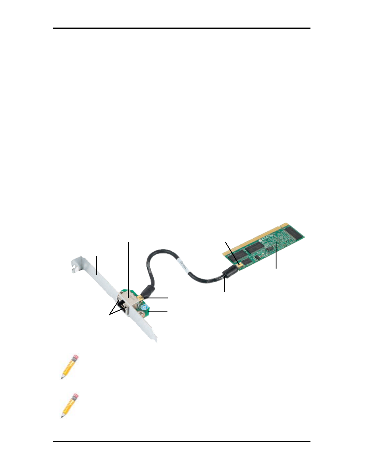
Refer to Figure 2-1 below for the configuration the entire SKT-0240L package and
AOC-SIM1U/AOC-SIM1U+ add-on card.
Figure 2-1. SKT-0240L Package and AOC-SIM1U/AOC-SIM1U+ Add-on Card
Dedicated Ethernet
(LAN) Port
Bracket
LAN LEDs
NOTE: You can also use LAN1 on the motherboard if you do not need the
dedicated LAN support. However, dedicated LAN is recommended for better
graphic support when the KVM feature is used.
NOTE: The SKT-0240L is included in the AOC-SIM1U/AOC-SIM1U+ shipping
package only.
Mini-USB
Connector (J3)
Mini-USB
Connector
AOC-USB2RJ45
CBL-0165L Cable
AOC-SIM1U(+)
Add-On Card
2-1
AOC-SIM1U/AOC-SIM1U+ Add-on Card User’s Manual
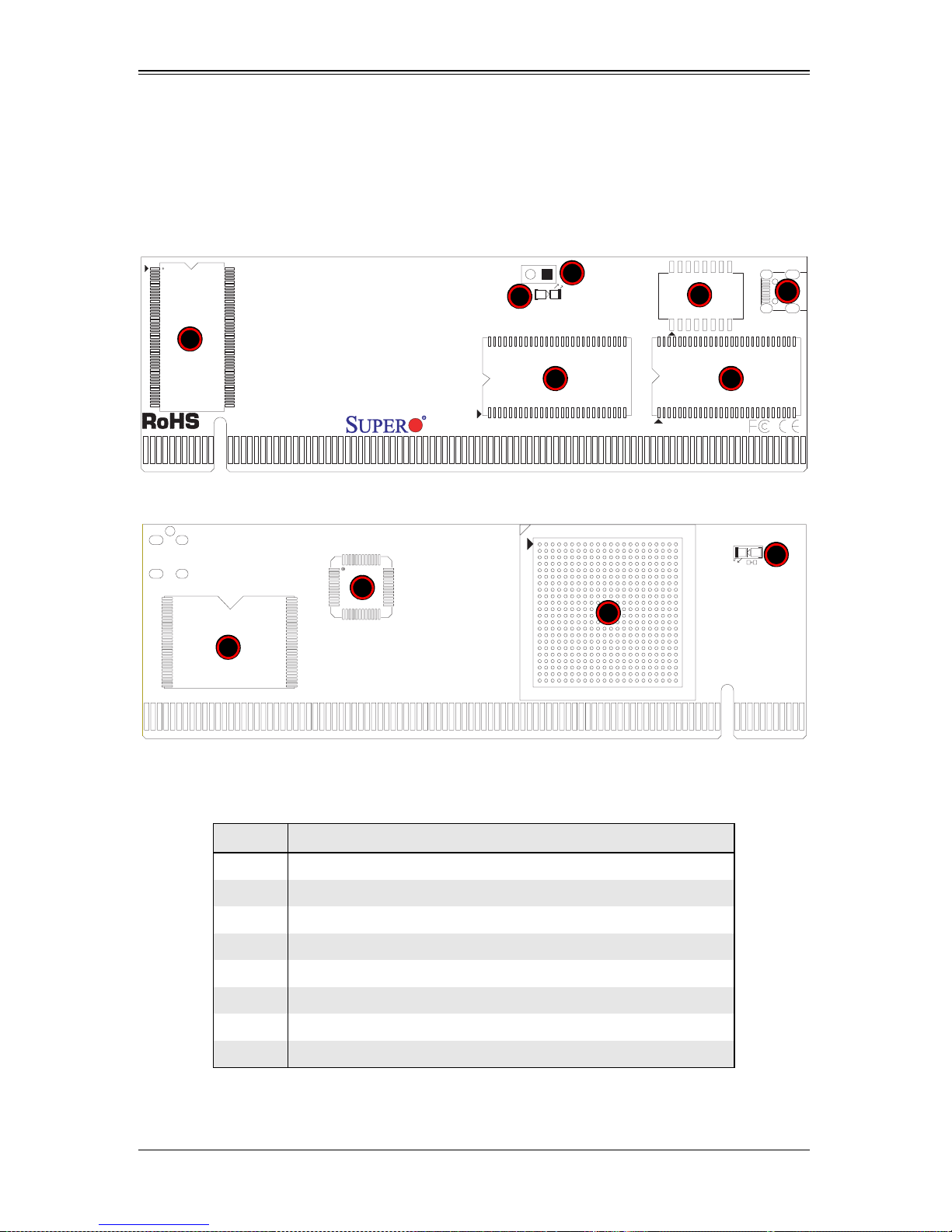
2-2 Components
The front components of the AOC-SIM1U/AOC-SIM1U+ add-on card are shown in
Figure 2-2. Rear components are shown in Figure 2-3.
Figure 2-2. AOC-SIM1U/AOC-SIM1U+ Add-on Card – Front View
1
5
6
1
SIM1U
Figure 2-3. AOC-SIM1U/AOC-SIM1U+ Add-on Card – Rear View
3
4
22
9
7
8
Table 2-1 lists all the AOC-SIM1U/AOC-SIM1U+ add-on card’s components.
Table 2-1. AOC-SIM1U/AOC-SIM1U+ Add-on Card Components
Number Description
1 V-RAM (64 Mb/166 MHz)
2 SDRAM (128 Mb/133 MHz)
3 Transformer
4 J3: Mini USB 9-pin Connector
5 JP5: Kira 100 Processor Reset
6 D3: Standby Power LED Indicator
10
7 Raritan's Kira 100 RISC System on Chip
8 Flash Memory
2-2
Chapter 2: Technical Specifications and Hardware Installation
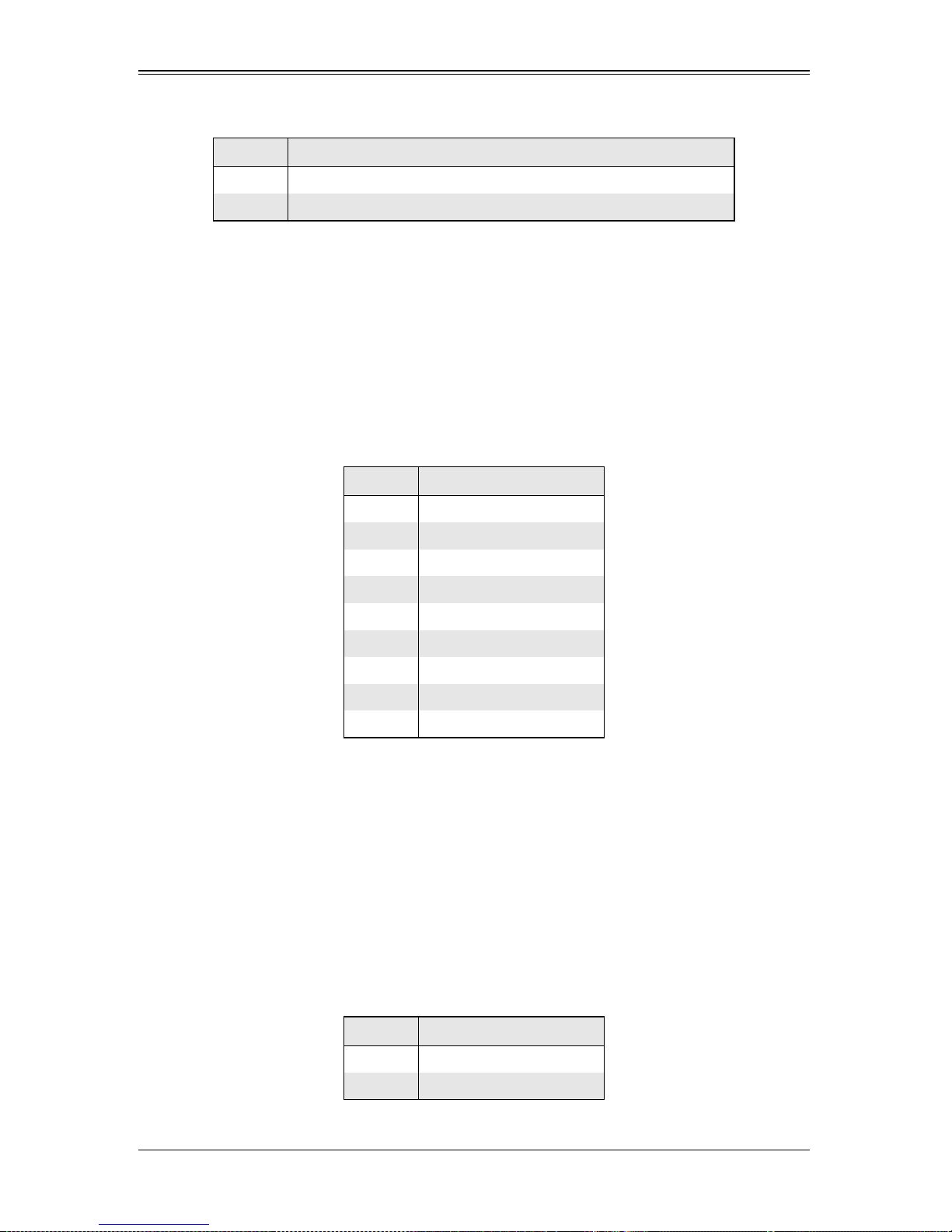
Table 2-1. AOC-SIM1U/AOC-SIM1U+ Add-on Card Components (Continued)
Number Description
9PHY LAN
10 Heartbeat LED
Mini USB Connector (J3)
There is a mini USB connector (J3) located on the AOC-SIM1U/AOC-SIM1U+ add-on
card and another mini USB connector is located on the AOC-USB2RJ45. Use Cable
CBL-0165L to connect the two mini USB connectors on both add-on cards for external
LAN access.
Refer to Section 2-1: "Connecting the AOC-SIM1U/AOC-SIM1U+ and AOC-USB2RJ45
Add-On Cards" on page 2-1 for details. See Table 2-2 for the pin definitions.
Table 2-2. Mini USB Pin Definitions (J3)
Pin # Definition
1Eth-TX_H
2 Eth-TX_L
3 Phy-100
4 Eth-RX_L
5Eth-RX_H
6 Phy-ACT
7 Dedicated LAN-Detected
8 3V-duall
9 Ground
RISC CPU Reset (JP5)
Jumper JP5 is used to reset the Kira 100 Processor, NIC, and R.T. Close Pin 1 and
Pin 2 to enable this function. After a reset or AC power-on, the AOC-SIM1U/
AOC-SIM1U+ add-on card will automatically detect if a cable (CBL-0165L) is connected.
If a cable is not detected, the AOC-SIM1U/AOC-SIM1U+ will transfer the Remote
Control function to LAN1 on the motherboard. If a cable is detected, the AOC-SIM1U/
AOC-SIM1U+ uses the dedicated LAN attached to it via the mini USB connector to
manage motherboard activities via the Remote Console. See Table 2-3 for jumper
settings.
Table 2-3. RISC CPU Reset
Setting Description
Open Disabled (Def ault)
Close Enabled
2-3
AOC-SIM1U/AOC-SIM1U+ Add-on Card User’s Manual
NOTE: The SKT-0240L is included in the AOC-SIM1U/AOC-SIM1U+ shipping
package only.
2-3 LED Indicators
Led indicators are described in this section below.
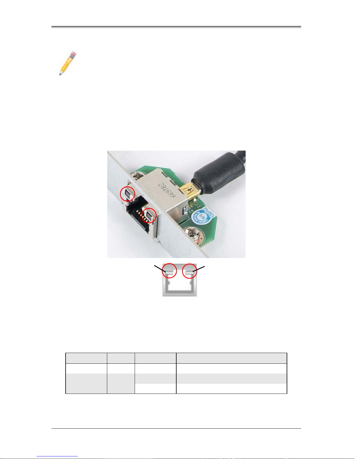
Dedicated LAN LED Indicators on the AOC-USB2RJ45
Figure 2-4. AOC-USB2RJ45 Dedicated LAN LED Indicators
Activity LED Link LED
There are two LAN LED Indicators located on the (Dedicated) LAN port on the
AOC-USB2RJ45 Add-On Card (see Figure 2-4). The green LED indicates activity, while
the power LED may be green or off to indicate the speed of the Ethernet connection.
See Table 2-4 for more information.
Table 2-4. AOC-USB2RJ45 Dedicated LAN LED Indicators
LED Color Activity Description
Activity LED Amber Flashing Active
Link LED Green
Off No Connection or 10 Mb/s
Green 100 Mb/s
2-4
Chapter 2: Technical Specifications and Hardware Installation
Standby Power LED Indicator (D3)
When this LED is on, the standby power is on. Be sure to remove power cables before
installing or removing components.
Heartbeat LED Indicator
The Heartbeat LED, located on the rear side of the AOC-SIM1U/AOC-SIM1U+ add-on
card, indicates the functionality and activity of the add-on card. This LED blinks when
the AOC-SIM1U/AOC-SIM1U+ is active.
However, when the Linux OS and the drivers are being loaded after each AC power-on
or reset, the Heartbeat LED is off for about a minute. It then goes on again to indicate
that the AOC-SIM1U/AOC-SIM1U+ is active. See Table 2-5 for details.
Table 2-5. Heartbeat LED
Activity Description
On (Blinking) AOC-SIM1U/AOC-SIM1U+ active
Off (for 1 minute) Loading Firmware
Off (Continuously) AOC-SIM1U/AOC-SIM1U+ is not active
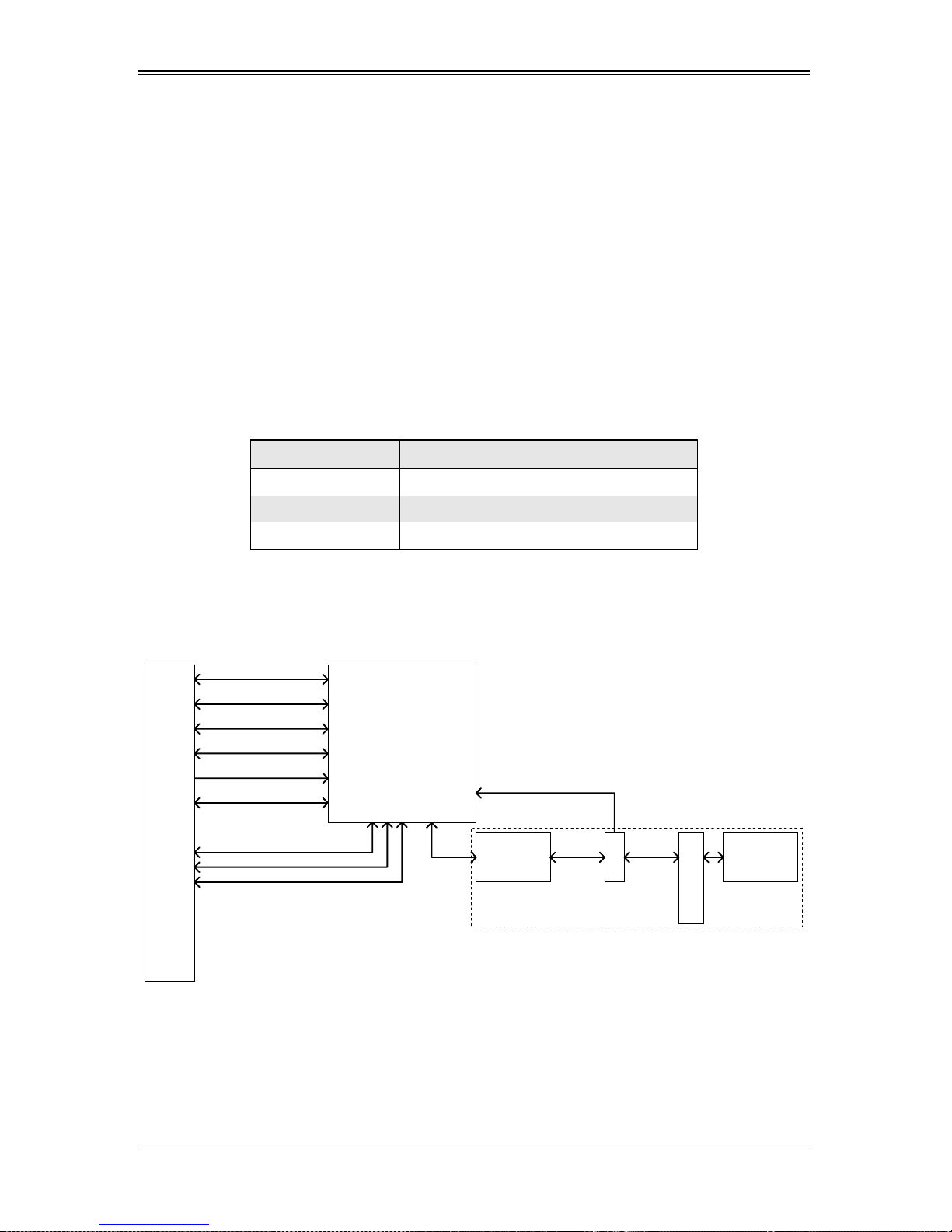
2-4 Block Diagram
Figure 2-5. AOC-SIM1U/AOC-SIM1U+ Add-on Card Block Diagram
UART Interface
USB Interface
LPC Interface
FML Interface
DVO interface
RMII
Mother Board SMDATA
Mother Board SMCLK
IPMI-200 Connector
Mother Board SMALT#
KIRA100
CABLE detection (Lo active)
GPIO24
Ethernet PHY
PIN 7
miniUSB
SIM1U only
RJ45
Dedicated LAN
mini USB cable
The block diagram for the AOC-SIM1U/AOC-SIM1U+ add-on card is shown in
Figure 2-5.
2-5
AOC-SIM1U/AOC-SIM1U+ Add-on Card User’s Manual
2-5 Installation
This section covers installation of the AOC-SIM1U/AOC-SIM1U+ add-on card into your
system.
SMC Motherboards with AOC-SIM1U/AOC-SIM1U+ Support
The following Supermicro motherboards support the AOC-SIM1U/AOC-SIM1U+ add-on
card:
• The X7DB8/X7DBE/X7DB8+/X7DBE+/X7DB8-X/X7DBE-X/X7DB3 Series
• The X7DA8/X7DAE/X7DVA-8/X7DVA-E/X7DVL-3/i Series (see Note below)
• The X7DVL-E Series
• The PDSM4+/PDSME+ Series
NOTE: KVM-over-LAN is not supported by the X7DA8, X7DAE or X7DVL-3/i
motherboards.
SIM1U Slot Locations
To properly use the AOC-SIM1U/AOC-SIM1U+ add-on card, be sure to install it in the
right slot. Refer to the motherboard layouts below for AOC-SIM1U/AOC-SIM1U+ slot
locations.
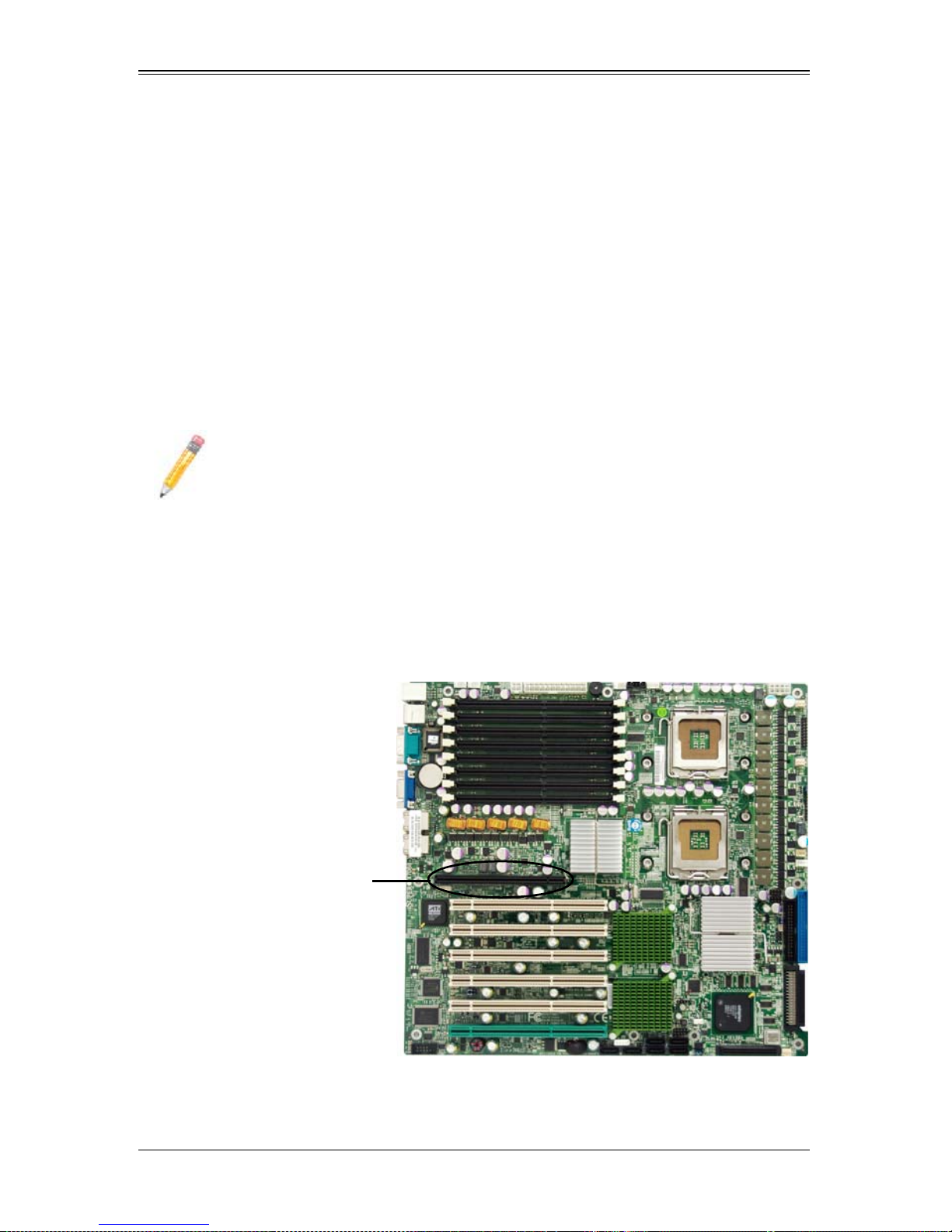
Figure 2-6. X7DB8/X7DBE/X7DB8+/X7DBE+/X7DB8-X/X7DBE-X/X7DB3 Series
SIM1U Slot (Slot 7)
2-6
Chapter 2: Technical Specifications and Hardware Installation
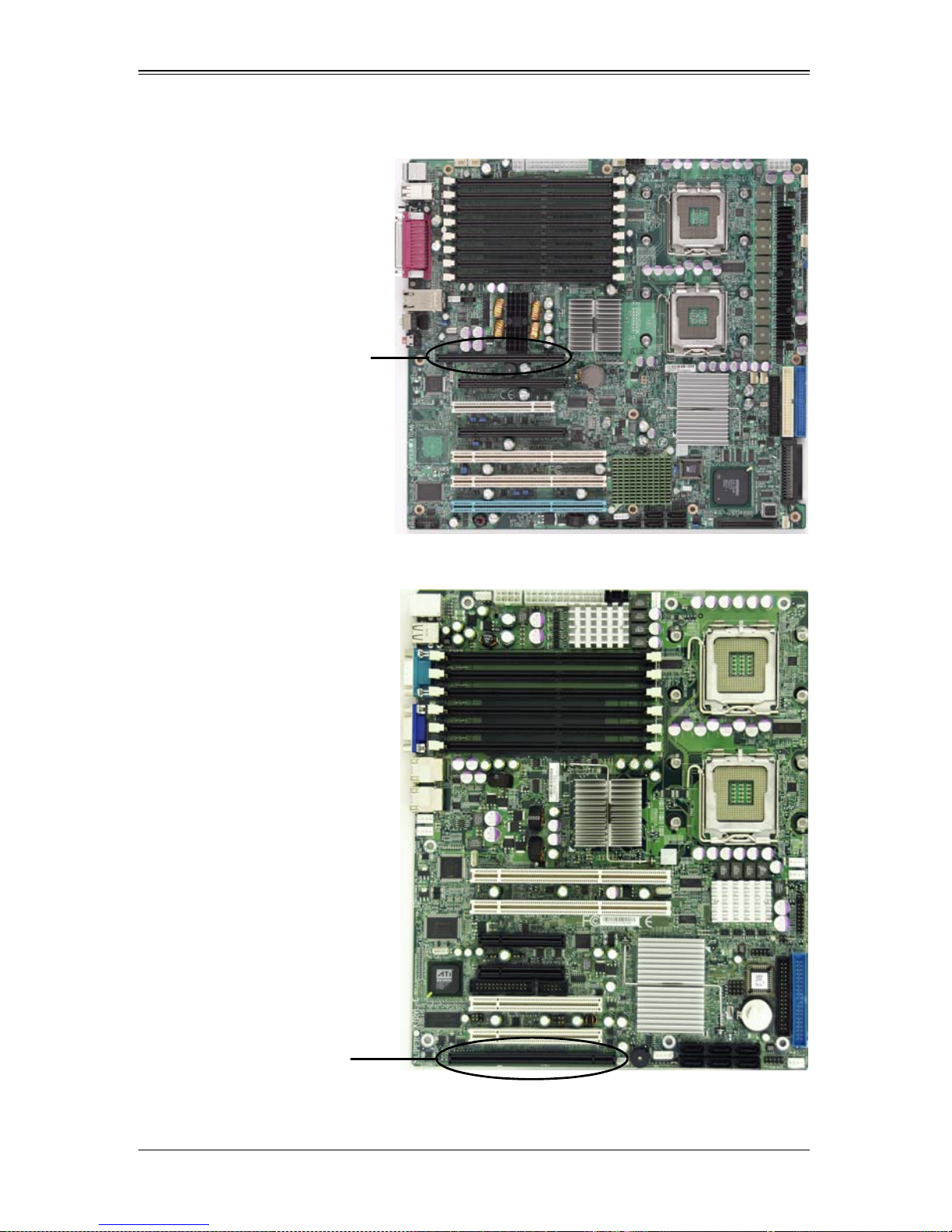
Figure 2-7. X7DA8/X7DAE/X7DVA-8/X7DVA-E/X7DVL-3/i Series
SIM1U Slot (Slot 7)
Figure 2-8. X7DVL-E
SIM1U Slot
2-7

AOC-SIM1U/AOC-SIM1U+ Add-on Card User’s Manual
Figure 2-9. PDSM4+/PDSME+ Series
SIM1U Slot
2-8

Chapter 3
Software Application and Usage
3-1 Introduction
With an independent I/O processor embedded in Raritan's Kira 100 RISC System Chip,
the AOC-SIM1U/AOC-SIM1U+ add-on card allows you to access, monitor, manage and
interface with systems that are in remote locations via LAN. The necessary utilities for
the access and configuration of the add-on card are included on the Supermicro
bootable CDs that came with your card. This section provides information on the
configuration and the access of the IPMI card on the network.
NOTE: KVM-over-LAN is available on the AOC-SIM1U+ only. All features and
options related to the functionality of KVM-over-LAN are supported by the
AOC-SIM1U+ only. In addition, KVM-over-LAN is not supported by the
following motherboards:
• X7DA8/X7DAE
• X7DVL-3/X7DVL-i.
3-2 Configuring IP/MAC Addresses and other Network
Settings
To configure IP/MAC addresses and other IPMI network settings using the IPMICFG
utility, use the procedure below.
Configuring an IP/MAC Address or Other IPMI
1. Run the IPMICFG utility from the bootable CD that came with your shipment.
2. Refer to the table below to configure the IP/MAC addresses.
Board IPMI MAC IP
X7 Series with LAN
82563EB, 82575
X7 Series with LAN
82573
H8 DDR2 Memory SIM1U IPMI Card Available IP/DHCP
H8QM3/i-x SIM1U
SIM1U
SIM1U
IPMI Card
Available IP/DHCP
LAN1 LAN1 on Mainboard
IPMI Card
Available IP/DHCP
LAN1 LAN1 on Mainboard
IPMI Card Available IP/DHCP Dedicated LAN
LAN1 LAN1 LAN1 on Mainboard
Communication
Through
Dedicated LAN
Dedicated LAN
Dedicated LAN
LAN1 on Mainboard
3-1

AOC-SIM1U/AOC-SIM1U+ Add-on Card User’s Manual
NOTE: When the SIM1U/+ card is used with the on-board 82573 LAN the HTTP
function of the SIM1U and KVM-over-LAN functions will not work.
3. Follow the instructions given in the Readme.txt file to configure Gateway IP/
Netmask IP addresses, to enable/disable DHCP and to configure other IPMI
settings.
NOTE: The Readme.txt file is included in the CD that came with your shipment.
A copy of the Readme.txt file, dated 07/11/2008, is also included below.
IPMICFG Version 1.10 (Build 080711) Copyright 2008 SuperMicro
Computer Inc.
Usage: IPMICFG params (Example: IPMICFG -m 192.168.1.123)
-m Show IP and MAC
-m IP Set IP (format: ###.###.###.###)
-a MAC Set MAC (format: ##:##:##:##:##:##)
-k Show Subnet Mask
-k Mask Set Subnet Mask (format: ###.###.###.###)
-dhcp Get the DHCP status
-dhcp on Enable the DHCP
-dhcp off Disable the DHCP
-g Show Gateway IP
-g IP Set Gateway IP (format: ###.###.###.###)
-r BMC cold reset
-garp on Enable the Gratuitous ARP
-garp off Disable the Gratuitous ARP
-fd Reset to the factory default
-ver Get Firmware revision
-vlan Get VLAN status
-vlan on [VLANtag] Enable the VLAN and set the VLAN tag
If VLANtag is not given it uses previously
.....................saved value.
-vlan off Disable the VLAN
-raw Send a RAW IPMI request and print response.
Format: NetFn LUN Cmd [Data1 ... DataN]
3-2

Chapter 3: Software Application and Usage
3-3 Accessing the AOC-SIM1U/AOC-SIM1U+ Add-on
Card
Use the procedure below to access the AOC-SIM1U/AOC-SIM1U+ add-on card from a
computer.
Using the Onboard LAN1 Connection
1. Choose a computer that is connected to the same network and open the IPMIView
utility.
2. Go to F
D
3. Select the system from the IPMI Domain. Type the LOGIN ID and PASSWORD in the
appropriate blanks to log into the IPMIView utility.
Using the Dedicated LAN
1. Choose a computer that is connected to the same network and open the browser.
2. Type in the IP address of each server that you want to connect in the address bar in
your browser.
3. Once the connection is made the L
ILE>NEW>SYSTEM. Type SYSTEM NAME, IP ADDRESS OF LAN1, and
ESCRIPTION in the appropriate blanks and press the ENTER key.
OGIN screen appears, as shown in Figure 3-1.
3-3
AOC-SIM1U/AOC-SIM1U+ Add-on Card User’s Manual
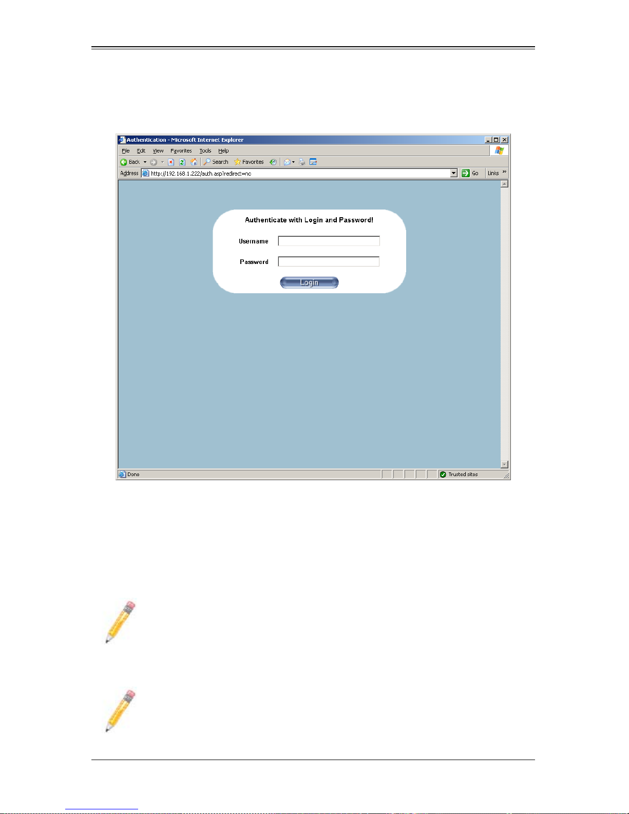
3-4 Logging In
Figure 3-1. Login Screen
Once you are connected to the remote server, the LOGIN screen appears (Figure 3-1).
To login, use the procedure below.
Logging In to the IPMICFG Utility using the Login Screen:
1. Type in your Username in the U
2. Type in your Password in the P
SERNAME box.
ASSWORD box and click on the LOGIN button.
NOTE: The default username is ADMIN. The default password is ADMIN.
OME PAGE screen (Figure 3-2) appears.
The H
NOTE: KVM-over-LAN is available on the AOC-SIMLP-B+ and AOC-SIMLP-3+
AOC-SIM1U/AOC-SIM1U+ add-on card only.
3-4
Chapter 3: Software Application and Usage
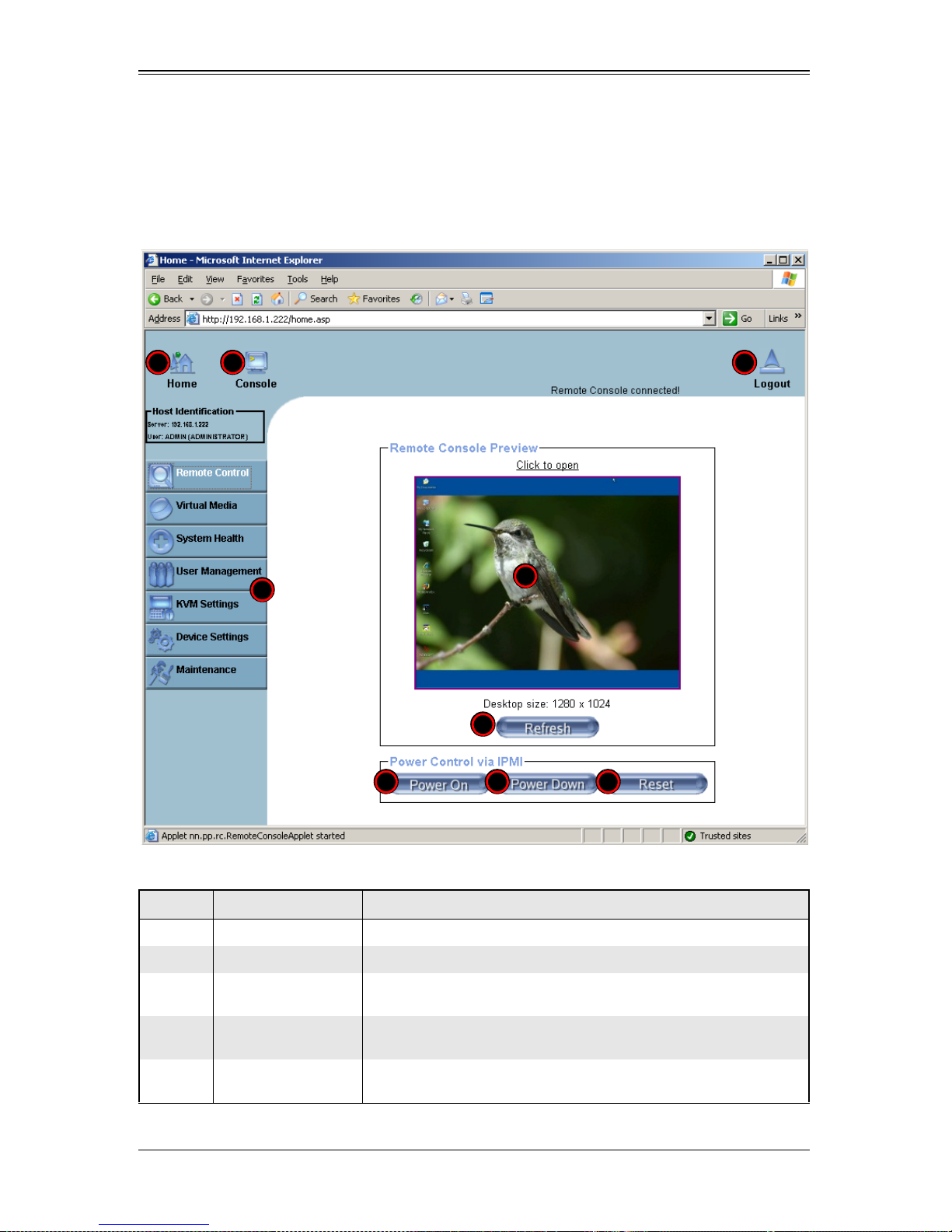
Home Page Screen
The HOME PAGE screen (Figure 3-2) appears after login. Table 3-1 lists and describes its
components.
Figure 3-2. Home Page Screen
1 2 4
9
6 7 8
3
5
Table 3-1. Home Page Screen Components
Item Name Description
1 Home Icon Click this icon to return to the HOME PAGE screen.
2 Console Icon Click this icon to go to the REMOTE CONSOLE screen.
3
Remote Console
Screen
Displayed in the window is the R
this window to go to the R
EMOTE CONSOLE screen.
EMOTE CONSOLE screen. Click on
4 Logout Icon
5 Refresh Button
Click on this icon to log out of the system. This will display the LOGIN
screen again (Figure 3-1).
Click on this icon to refresh the screen of the remote console
preview.
3-5
 Loading...