

Page 1
SUPER
®
AOC-SAT2-MV8
USER'S GUIDE
Rev. 1.0
Page 2

AOC-SAT2-MV8 User's Guide
The information in this User’s Guide has been carefully reviewed and is believed to be
accurate. The vendor assumes no responsibility for any inaccuracies that may be
contained in this document, makes no commitment to update or to keep current the
information in this manual, or to notify any person or organization of the updates.
Please
Note: For the most up-to-date version of this manual, please see our
web site at www.supermicro.com.
SUPERMICRO COMPUTER reserves the right to make changes to the product described in
this manual at any time and without notice. This product, including software, if any, and
documentation may not, in whole or in part, be copied, photocopied, reproduced, translated
or reduced to any medium or machine without prior written consent.
IN NO EVENT WILL SUPERMICRO COMPUTER BE LIABLE FOR DIRECT, INDIRECT,
SPECIAL, INCIDENTAL, OR CONSEQUENTIAL DAMAGES ARISING FROM THE USE OR
INABILITY TO USE THIS PRODUCT OR DOCUMENTATION, EVEN IF ADVISED OF THE
POSSIBILITY OF SUCH DAMAGES. IN PARTICULAR, THE VENDOR SHALL NOT HAVE
LIABILITY FOR ANY HARDWARE, SOFTWARE, OR DATA STORED OR USED WITH THE
PRODUCT, INCLUDING THE COSTS OF REPAIRING, REPLACING, INTEGRATING,
INSTALLING OR RECOVERING SUCH HARDWARE, SOFTWARE, OR DATA.
Any disputes arising between manufacturer and customer shall be governed by the laws of
Santa Clara County in the State of California, USA. The State of California, County of
Santa Clara shall be the exclusive venue for the resolution of any such disputes.
Supermicro's total liability for all claims will not exceed the price paid for the hardware
product.
Unless you request and receive written permission from SUPER MICRO COMPUTER, you
may not copy any part of this document.
Information in this document is subject to change without notice. Other products and
companies referred to herein are trademarks or registered trademarks of their respective
companies or mark holders.
Copyright © 2005 by SUPER MICRO COMPUTER INC.
All rights reserved.
Printed in the United States of America
2
Page 3
Table of Contents
Table of Contents
1. Introduction..................................................................4
1.1. Overview..................................................................................4
1.2. Technical Specifications.......................................................... 5
1.3. LED Indicators and Pin Definitions ........................................ 7
1.4. Connectors and Pin Definitions .............................................. 8
2. Safety Guidelines.........................................................9
3. Installing the SAT2-MV8 Driver....................................10
3.1. Creating the driver floppy disk .............................................10
3.2. Adding the Driver into an Existing System.........................10
3.3. Installing the driver into a new system ..............................12
4. Troubleshooting.................................................... ..... 18
5. Contacting Supermicro............................................... 21
3
Page 4
AOC-SAT2-MV8 User's Guide
1. Introduction
This manual is written for system integrators, PC technicians and
knowledgeable PC users who intend to integrate Supermicro's SAT2-MV8
SATA Controller into their system. It provides detailed information for the
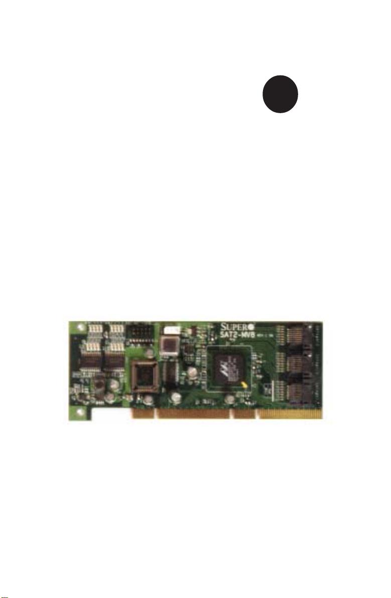
installation and use of the SAT2-MV8 card. The Supermicro SAT2-MV8 offers an innovative, complete and cost effective solution to the ever-increasing demands of disk density and data integrity of today's servers.
1.1 Overview
The SAT2-MV8 is a highly efficient, highly compatible and easy-to-use SATA
RAID Controller that allows the user to configure RAID functions by using
Marvell's 88SX6081 8-port Serial ATA Host Controller, offering 64-bit PCI-X
bus interface with high performance features. With the SATA physical
interface support at 1.5 and 3.0 Gbps, the SAT2-MV8 is a high speed, high
bandwidth RAID Controller that can integrate multiple high capacity drives to
provide the user with maximum storage space.
Product Features
• Low profile Form Factor (w/ the PCB size of 2.5" H x 6.4" W)
• Marvell's 88SX6081 8-port Serial ATA Host Controller
• Eight SATA ports @ 1.5 or 3.0 Gigabits per second (Gbps)
• 64-bit, 133 MHz PCI-X bus
• Flash BIOS Interface
• Presence LED Indicator and Activity Indicator for each port
• Software RAID 0, RAID 1, RAID 10 and JBOD (-simple volume) supported
(*Note: Some operating systems might not support Software RAID.)
• Bootability from a single drive.
Operating Systems supported
• Windows 2000, XP, 2003, XP EM64T, 2003 EM64T
• Linux: (-source code provided)--the driver disks currently available:
• RedHat 9 (2.4.20-6 and 2.4.20-8)
• RedHat Enterprise Linux 3 Update 2, Update 3, and Update 4.
• RedHat Enterprise Linux 3 EM64T/X86_64 Update 3 and Update 4.
• RedHat Enterprise Linux 4 and RedHat Enterprise Linux 4 EM64T/X86_64.
• SuSE 9.1, 9.2 and SuSE Linux Enterprise Server 9.
• Fedora Core 3.
An Important Note to the User
• All images and layouts shown in this user's guide were based upon
the latest revision available at the time of publishing. The card you've
received may or may not look exactly the same as the ones shown in
this manual.
4
Page 5
Technical Specifications
1.2 Technical Specifications
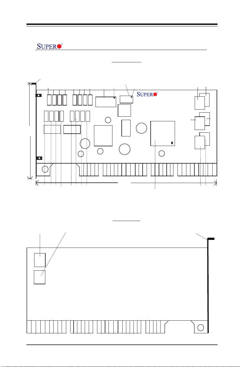
SAT2-MV8 Card Layout and Jumper Locations
Front view
C
Pin 1
SATA I2C
50CN3
6.4”
2
SATA I
JS10
LCX
16373
Pin 1
SAT2-MV8
Rev. 1.0
88SX6081
Marvell SATA
Controller
SATA
CTLR
SATA
3.14”
bracket
Act.7 LED
Act.6 LED
ACT 7
ACT 6
PRE 6
PRE7
LVC245A
PRE. 6 LED
PRE. 7 LED
Act.5 LED
Act.3 LED
Act.4 LED
ACT 5
ACT 4
ACT 3
PRE 3
PRE 4
PRE 5
LVC245A
PRE. 5 LED
PRE. 4 LED
PRE. 3 LED
Act.0 LED
Act.1 LED
Act.2 LED
Ext. ACT LED
ACT 2
ACT 1
ACT0
PRE 0
PRE 2
PRE 1
PRE. 0 LED
PRE. 1 LED
PRE. 2 LED
Ext.Act.LED
JS9
BIOS Chip
SATA 4
JS3
SATA 4
JS2
SATA 2
JS1
SATA 0
SATA 0
SATA 5
SATA 5
SATA 3
SATA 3
SATA 1
SATA 1
JS8
JS7
SATA 7
SATA6
SATA 6SATA 7
PCI X 133
Rear view
bracket
Rear View
5
Page 6
AOC-SAT2-MV8 User's Guide
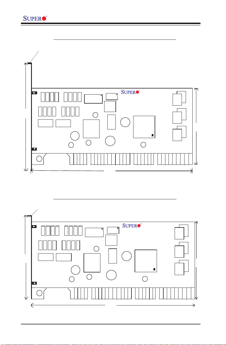
Front view (SAT2-MV8 w/Full-Height Bracket)
Full-Height bracket
ACT 2
PRE 2
ACT 1
PRE 1
ACT0
PRE 0
Ext. ACT LED
4.75”
ACT 7
PRE 6
PRE7
LVC245A
ACT 6
PRE 5
ACT 5
ACT 4
PRE 4
LVC245A
ACT 3
PRE 3
JS9
BIOS Chip
SATA I2C
JS10
50CN3
6.4”
LCX
SAT2-MV8
Rev. 1.0
16373
88SX6081
Marvell SATA
Controller
JS3
SATA 5
SATA 4
JS2
SATA 3
SATA 2
2.5”
JS1
SATA 1
SATA 0
Front view (SAT2-MV8 w/Low-Profile Bracket)
Low-Profile bracket
ACT 7
ACT 6
ACT 5
PRE 4
PRE 5
PRE 6
PRE7
3.14”
LVC245A
LVC245A
ACT 4
ACT 3
PRE 3
ACT 2
PRE 2
PRE 1
ACT 1
PRE 0
Ext. ACT LED
ACT0
SATA I2C
JS9
BIOS Chip
JS10
50CN3
LCX
6.4”
6
SAT2-MV8 Rev. 1.0
16373
88SX6081
Marvell SATA
Controller
JS3
SATA 5
SATA 4
JS2
SATA 3
SATA 2
2.5”
JS1
SATA 1
SATA 0
Page 7

LED Indicators and Pin Definitions
1.3 LED Indicators and Pin Definitions
SATA Presence LED
Indicators
Serial ATA Presence LED Indicators (DS0-DS7) indicate the presence of SATA ports (0-7). See the
Table on the right for pin definitions.
SATA Activity LED
Indicators
Serial ATA Activity LED Indicators
(DS8-DS15) indicate the activity
status of SATA ports (0-7). See
the table on the right for pin definitions.
SATA Presence LED Indidators
Pin Definitions (DS0-DS7)
DS # Definition
DS0 SATA0_Present
DS1 SATA1_Present
DS2 SATA2_Present
DS3 SATA3_Present
SATA Activity LED Indidators
Pin Definitions (DS8-DS15)
DS# Definition
DS8 SATA0_Act
DS9 SATA1_Act
DS10 SATA2_Act
DS11 SATA3_Act
DS# Definition
DS4 SATA4_Present
DS5 SATA5_Present
DS6 SATA6_Present
DS7 SATA7_Present
DS# Definition
DS12 SATA4_Act
DS13 SATA5_Act
DS14 SATA6_Act
DS15 SATA7_Act
(*Refer to the layout on Page 5 for the locations of Connectors and
the LED Indicators.)
7
Page 8

AOC-SAT2-MV8 User's Guide
1.4 Connectors and Pin Definitions
Extended Activity LED
Connectors
Extended Activity LED Connector
(JS9) indicates the status of Extended Activity of SATA ports.
This connector is only compatible
with Supermicro's SATA panel
and requires SATA Cables such
as CBL-0069, CBL-0055, CBL0056, or CBL-0057 installed to
function properly.
RAID SMB (I2 C) Connector
RAID SMB I2 C Connector (JS10),
monitors the status of RAID for
Serial ATA ports. See the table
on the right for pin definitions.
4
C
8K
Extended ACT. LED Pin
Definitions (JS9)
Pin#
1-8
Activity Output for
Common Ground
C
K
3
SATA RAID I2C Pin
Definitions (JS10)
Pin#
1
2
3
7
Definition
Drives 0-7
Unused
1
2
Definition
Data
Ground
Clock
23
6
1
5
SATA Connections
The following onboard connectors
(JS1-3, JS7-8) support Serial ATA
Ports (#0-7). See the table on the
right for detailed information.
JS1 SATA Ports 0, 1
JS2 SATA Ports 2, 3
JS3 SATA Ports 4, 5
SATA Port Connections
(JS 1-3, JS 7-8)
JS# Port#
JS# Port#
JS7 SATA Port 6
JS8 SATA Port 7
(*Refer to the layout on Page 5 for the locations of Connectors and
the LED Indicators.)
8
Page 9

Safety Guidelines
2. Safety Guidelines
To avoid personal injury and property damage, please carefully
follow all the safety steps listed below when accessing your
system or handling the components:
ESD Safety Guidelines
Electric Static Discharge (ESD) can damage electronic components. To
prevent damage to your system. it is important to handle it very carefully. The
following measures are generally sufficient to protect your equipment from
ESD.
• Use a grounded wrist strap designed to prevent static discharge.
• Touch a grounded metal object before removing a component from the
antistatic bag.
• Handle the RAID card by its edges only; do not touch its components,
peripheral chips, memory modules or gold contacts.
• When handling chips or modules, avoid touching their pins.
• Put the card and peripherals back into their antistatic bags when not in
use.
General Safety Guidelines
• Always disconnect power cables before installing or removing any components from the computer, including the RAID card.
• Use only the correct type of bracket for the chassis. Please use a fullheight bracket for a 1U, 3U, 4U, Tower, or a Pedestal system. Use a lowprofile bracket for a 2U or some of the proprietary chassis. Make sure to
secure the bracket in the host system cabinet. (*Note: When used in a 1U
system, the card with a full-height bracket is mounted into the riser card.)
• Disconnect the power cable before removing the Extended LED, data or
I2C cables from the riser card.
• Make sure that the card is securely seated in the PCI slot to prevent
damage to the system due to power shortage.
• Do not force a cable connector onto the controller or a drive.
9
Page 10

AOC-SAT2-MV8 User's Guide
3. Installing the SAT2-MV8 Driver
3.1 Creating the driver floppy disk:
A CDROM that contains the drivers for the Windows OS, Linux OS, and the
Controller BIOS is included in the shipping package. Please locate the
CDROM before installing the driver. (*Note: this CDROM does not perform
Auto-boot or auto-play.)
For the Windows 32-bit Operating System:
• Copy all files from the folder: \Windows_3_4_1\build\Windows\i386\Free
into a blank, formatted floppy disk.
For the Windows 64-bit Operating System:
• Copy all files from the folder: \Windows_3_4_1\build\Windows\amd64
\Free into a blank, formatted floppy disk.
For the Linux Operating System:
For an existing system:
• Use the source code from the folder: \Linux_3_4_0 to compile.
For a new system:
• Use the tool- rawwritewin.exe to write the driver images stored in the
folder: \DiskImag\linux to create a driver disk. (*Note: The folder\DiskImag\linux is included in Supermicro's CD ROM that came with your
shipping. However, the file-rawwritewin.exe is not included.)
3.2 Adding the driver into an existing system
(*Note: An existing system is a system that has an operating system
already installed and the SAT2-MV8 driver is being installed as a
Secondary Controller.)
For the Windows Operating System
a. Install the controller and make sure that the BIOS screen as shown be-
low displays:
10
Page 11

Installing the SAT2-MV8 Driver
b. Start the Windows OS. The Windows OS will launch the "Found New
Hardware Wizard" and search for the installer driver.
c. Insert the driver floppy disk that you've created into the floppy drive,
select the floppy drive as the source, and press the <enter> key.
d. Continue clicking <Next> until the driver is successfully installed.
e. Remove the driver disk from the FDD drive and restart the system to
complete the installation process.
For the Linux Operating System
a. Insert the CDROM that contains the Linux OS driver in the CD drive.
b. At the # prompt, type: mount /dev/cdrom /mnt/cdrom and press <enter> to
mount the CDROM directory into the system directory.
c. At the # prompt, type: cd /mnt/cdrom/Linux_3_4_0 and press <enter> to
change the directory to the CDROM directory.
d. Read the README.txt file and exit.
e. At the # prompt, type: cd /mnt/cdrom/Linux_3_4_0/Docs/ and press <en-
ter>.
f. Read the documents included carefully and follow the instructions given
to create the driver and install it into the system.
11
Page 12

AOC-SAT2-MV8 User's Guide
3.3 Installing the driver into a new system
(*Note: A new system is a system that has no operating system
installed yet, and the SAT2-MV8 driver installation is a part of the OS
installation.)
For the Windows Operating System
a. Install the controller and make sure that the BIOS screen displays as
shown on the previous page.
b. Insert the Windows Setup CD and boot from it.
c. When prompted at the bottom of the screen to install a third party driver,
press the <F6> key. (*Note: You have only 5 seconds to press <F6>. If
you miss it, you will need to restart the system and repeat this step
again.)
d. Insert the driver disk into the system, and wait until you are prompted to
install a driver. Press <S> to specify that the driver is included in an
additional device--the floppy disk, and press <Enter>.
e. When the Marvell's driver disk--"Marvell Serial ATA PCI-X Adapter" is
located, press <Enter>.
f. Press <Enter> again to continue with the Windows OS installation.
12
Page 13

Installing the SAT2-MV8 Driver
For the Red Hat Linux Operating System
a. Insert the Linux Driver into your floppy disk drive and press <Enter>. A
Linux bootup screen will display as shown below:
b. At the boot prompt, type: linux dd as shown in the screen below.
c. After you've typed: linux dd at the prompt, press <Enter>. The system
starts initializing the driver. Then, follow the instructions when prompted
to complete the installation process.
13
Page 14

AOC-SAT2-MV8 User's Guide
For the SuSE Linux Operating System
(*Note: The screen shot shown below was taken from a system based on
the SuSE Linux 9.2 Installation. Other SuSE systems may display screens
that are different from the ones included in the manual. However, the
installation procedures listed below apply to all SuSE Linux systems.)
a. Extract the image driver from \DiskImag\Linux\x86_32 into a blank, for-
matted disk.
b. Boot up the system from SuSE Linux Installation CD ROM.
c. When the screen as shown below displays, highlight "Installation", press
<F6> ( to add the Installation Driver), and hit <Enter>.
d. Follow the instructions given at the prompt to complete the installation
process.
14
Page 15

Troubleshooting
4. Troubleshooting
1. Problem: The SAT2-MV8's BIOS does not show up in DOS.
Recommended Solutions:
• Make sure that the system has enough expansion ROM to initialize the
card. Remove other add-in cards if possible.
• Make sure that the card is properly and fully seated in the PCI slot.
• Check if the motherboard's BIOS is updated. (You can download a updated BIOS from our web site at: www.supermicro.com.)
2. Problem: I cannot see the card in the operating system.
Recommended Solutions:
• Make sure that the card is shown in the BIOS. If the card is shown in the
BIOS, a screen shown below will display. If it is not shown in the BIOS,
please find out the root cause of the problem by following the steps
listed above.
• Make sure that the driver for the card is installed in the system.
15
Page 16

AOC-SAT2-MV8 User's Guide
3. Problem: I cannot see the hard drives that are connected to
the controller.
Recommended Solutions:
• Make sure that there is power supply to the hard drives.
• Check the SATA cable to make sure that there are no loose connections
between the card and the hard drives.
• If the hard drives are connected through a SATA back panel, make sure
that there is power supply to the back panel, and there are no loose
connections between the back panel and the controller. Also make sure
that the hard drives are properly seated in the drive bay.
• If possible, swap the drives around to determine if the drive connections
or the controller is bad.
4. I cannot create software RAID in the operating system.
Recommended Solutions:
• Make sure that the operating system supports software RAID. If not sure,
please check with the software company that produces the OS.
• Make sure that more than one drives are seen by the OS.
Contacting Supermicro's Technical Support:
If you still have problems after trying out all the recommended solutions,
please contact our Tech. Support @ (408)503-8000 or visit our web site
@ www.supermicro.com/support/.
16
Page 17

5. Contacting Supermicro
Headquarters
Address: SuperMicro Computer, Inc.
980 Rock Ave.
San Jose, CA 95131 U.S.A.
Tel: +1 (408) 503-8000
Fax: +1 (408) 503-8008
Email: marketing@supermicro.com (General Information)
support@supermicro.com (Technical Support)
Web Site: www.supermicro.com
Europe
Address: SuperMicro Computer B.V.
Het Sterrenbeeld 28, 5215 ML
's-Hertogenbosch, The Netherlands
Tel: +31 (0) 73-6400390
Fax: +31 (0) 73-6416525
Email: sales@supermicro.nl (General Information)
support@supermicro.nl (Technical Support)
rma@supermicro.nl (Customer Support)
Asia-Pacific
Address: SuperMicro, Taiwan
4F, No. 232-1 Liancheng Road
Chung-Ho 235, Taipei Hsien, Taiwan, R.O.C.
Tel: +886-(2) 8226-3990
Fax: +886-(2) 8226-3991
Web Site: www.supermicro.com.tw
Technical Support:
Email: support@supermicro.com.tw
Tel: 886-2-8228-1366, ext.132 or 139
17
Page 18

AOC-SAT2-MV8 User's Guide
6. Product Compliance Information
The SAT2-MV8 is compliant with the following safety standards/
requirements:
* USA: FCC 47 CFR, Part 15, subpart B
* European Union: EN 55022
EN 55024
18
 Loading...