

Supermicro 7047A-73, Supero 7047A-73, Supero 7047A-T User Manual
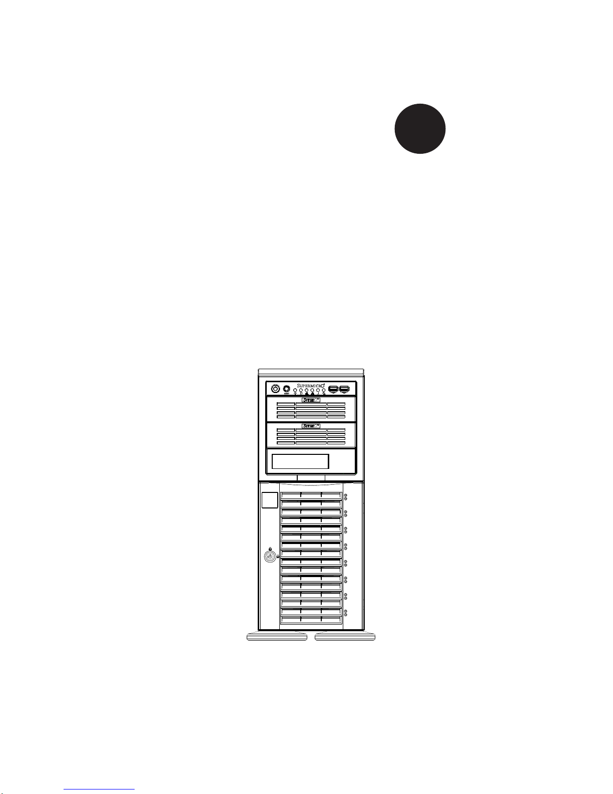
SUPER
SuperWorkstation
7047A-73
7047A-T
®
USER’S MANUAL
1.0

The information in this User’s Manual has been carefully reviewed and is believed to be accurate.
The vendor assumes no responsibility for any inaccuracies that may be contained in this document,
makes no commitment to update or to keep current the information in this manual, or to notify any
person or organization of the updates. Please Note: For the most up-to-date version of this
manual, please see our web site at www.supermicro.com.
Super Micro Computer, Inc. ("Supermicro") reserves the right to make changes to the product
described in this manual at any time and without notice. This product, including software and documentation, is the property of Supermicro and/or its licensors, and is supplied only under a license.
Any use or reproduction of this product is not allowed, except as expressly permitted by the terms
of said license.
IN NO EVENT WILL SUPERMICRO BE LIABLE FOR DIRECT, INDIRECT, SPECIAL, INCIDENTAL,
SPECULATIVE OR CONSEQUENTIAL DAMAGES ARISING FROM THE USE OR INABILITY TO
USE THIS PRODUCT OR DOCUMENTATION, EVEN IF ADVISED OF THE POSSIBILITY OF
SUCH DAMAGES. IN PARTICULAR, SUPERMICRO SHALL NOT HAVE LIABILITY FOR ANY
HARDWARE, SOFTW ARE, OR DA TA STORED OR USED WITH THE PRODUCT, INCLUDING THE
COSTS OF REPAIRING, REPLACING, INTEGRATING, INSTALLING OR RECOVERING SUCH
HARDWARE, SOFTWARE, OR DATA.
Any disputes arising between manufacturer and customer shall be governed by the laws of Santa
Clara County in the State of California, USA. The State of California, County of Santa Clara shall
be the exclusive venue for the resolution of any such disputes. Super Micro's total liability for all
claims will not exceed the price paid for the hardware product.
FCC Statement: This equipment has been tested and found to comply with the limits for a Class A
digital device pursuant to Part 15 of the FCC Rules. These limits are designed to provide reasonable
protection against harmful interference when the equipment is operated in a commercial environment. This equipment generates, uses, and can radiate radio frequency energy and, if not installed
and used in accordance with the manufacturer’s instruction manual, may cause harmful interference
with radio communications. Operation of this equipment in a residential area is likely to cause harmful
interference, in which case you will be required to correct the interference at your own expense.
California Best Management Practices Regulations for Perchlorate Materials: This Perchlorate warning applies only to products containing CR (Manganese Dioxide) Lithium coin cells. “Perchlorate
Material-special handling may apply. See www.dtsc.ca.gov/hazardouswaste/perchlorate”
WARNING: Handling of lead solder materials used in this
product may expose you to lead, a chemical known to the
State of California to cause birth defects and other reproductive harm.
Manual Revision 1.0
Release Date: March 13, 2012
Unless you request and receive written permission from Super Micro Computer, Inc., you may not
copy any part of this document.
Information in this document is subject to change without notice. Other products and companies
referred to herein are trademarks or registered trademarks of their respective companies or mark
holders.
Copyright © 2012 by Super Micro Computer, Inc.
All rights reserved.
Printed in the United States of America

Preface
About This Manual
This manual is written for professional system integrators and PC technicians. It
provides information for the installation and use of the SuperWorkstation 7047A73/7047A-T. Installation and maintenance should be performed by experienced
technicians only.
The SuperWorkstation 7047A-73/7047A-T is a high-end system based on the
SC743TQ-1200B-SQ tower/4U rackmount chassis and the X9DA7 (7047A-73) or
X9DAi (7047A-T) serverboard.
Preface
Manual Organization
Chapter 1: Introduction
The fi rst chapter provides a checklist of the main components included with the
system and describes the main features of the X9DA7 and X9DAi serverboards
and the SC743TQ-1200B-SQ chassis.
Chapter 2: Server Installation
This chapter describes the steps necessary to setup the SuperWorkstation 7047A73/7047A-T into a rack and check out the server confi guration prior to powering
up the system. If your system was ordered without processor and memory components, this chapter will refer you to the appropriate sections of the manual for
their installation.
Chapter 3: System Interface
Refer here for details on the system interface, which includes the functions and
information provided by the control panel on the chassis as well as other LEDs
located throughout the system.
iii

SuperWorkstation 7047A-73/7047A-T User's Manual
Chapter 4: System Safety
You should thoroughly familiarize yourself with this chapter for a general overview
of safety precautions that should be followed when installing and servicing the
SuperWorkstation 7047A-73/7047A-T.
Chapter 5: Advanced Serverboard Setup
Chapter 5 provides detailed information on the X9DA7/X9DAi serverboard, including the locations and functions of connections, headers and jumpers. Refer to this
chapter when adding or removing processors or main memory and when reconfi g-
uring the serverboard.
Chapter 6: Advanced Chassis Setup
Refer to Chapter 6 for detailed information on the SC743TQ-1200B-SQ chassis.
You should follow the procedures given in this chapter when installing, removing
or reconfi guring SAS or peripheral drives and when replacing system power supply
units and cooling fans.
Chapter 7: BIOS
The BIOS chapter includes an introduction to BIOS and provides detailed information on running the CMOS Setup Utility.
Appendix A: BIOS Error Beep Codes
Appendix B: System Specifi cations
iv

Notes
Preface
v

SuperWorkstation 7047A-73/7047A-T User's Manual
Table of Contents
Chapter 1 Introduction
1-1 Overview .........................................................................................................1-1
1-2 Serverboard Features .....................................................................................1-2
Processors ......................................................................................................1-2
Memory ...........................................................................................................1-2
Onboard SAS (7047A-73 only) .......................................................................1-2
SATA ..............................................................................................................1-2
PCI Expansion Slots ....................................................................................... 1-2
Onboard Controllers/Ports ..............................................................................1-3
1-3 Chassis Features ............................................................................................1-3
System Power ................................................................................................. 1-3
SAS Subsystem .............................................................................................. 1-3
Front Control Panel .........................................................................................1-3
Cooling System ............................................................................................... 1-3
1-4 Contacting Supermicro ....................................................................................1-5
Chapter 2 Installation
2-1 Overview .........................................................................................................2-1
2-2 Unpacking the System .................................................................................... 2-1
2-3 Preparing for Setup .........................................................................................2-1
Choosing a Setup Location ............................................................................. 2-2
Rack Precautions ............................................................................................ 2-2
Server Precautions .......................................................................................... 2-2
Rack Mounting Considerations .......................................................................2-3
Ambient Operating Temperature ................................................................ 2-3
Reduced Airfl ow .........................................................................................2-3
Mechanical Loading ................................................................................... 2-3
Circuit Overloading .....................................................................................2-3
Reliable Ground ......................................................................................... 2-3
2-4 Installing the System into a Rack ................................................................... 2-4
Identifying the Sections of the Rack Rails ...................................................... 2-4
Installing the Chassis Rails .............................................................................2-5
Installing the Rack Rails .................................................................................2-6
Installing the System into the Rack ................................................................ 2-7
vi

Table of Contents
Chapter 3 System Interface
3-1 Overview .........................................................................................................3-1
3-2 Control Panel Buttons ..................................................................................... 3-1
Power ..............................................................................................................3-1
Reset ...............................................................................................................3-1
3-3 Control Panel LEDs ........................................................................................3-2
Power ..............................................................................................................3-2
HDD .................................................................................................................3-2
NIC1 ................................................................................................................3-2
NIC2 ................................................................................................................3-2
Overheat/Fan Fail ........................................................................................... 3-2
Power Fail .......................................................................................................3-3
3-4 Drive Carrier LEDs ..........................................................................................3-3
Chapter 4 System Safety
4-1 Electrical Safety Precautions .......................................................................... 4-1
4-2 General Safety Precautions ............................................................................4-2
4-3 ESD Precautions ............................................................................................. 4-3
4-4 Operating Precautions .................................................................................... 4-4
Chapter 5 Advanced Serverboard Setup
5-1 Handling the Serverboard ............................................................................... 5-1
Precautions .....................................................................................................5-1
Unpacking .......................................................................................................5-2
5-2 Serverboard Installation ..................................................................................5-2
5-3 Connecting Cables .......................................................................................... 5-3
Connecting Data Cables ................................................................................. 5-3
Connecting Power Cables ..............................................................................5-3
Connecting the Control Panel ......................................................................... 5-3
5-4 I/O Ports ..........................................................................................................5-4
5-5 Processor and Heatsink Installation................................................................5-5
Installing an LGA 2011 Processor ................................................................... 5-5
Installing a CPU Heatsink ............................................................................... 5-8
Removing the Heatsink ................................................................................... 5-9
5-6 Installing Memory Modules ........................................................................... 5-10
Installing & Removing DIMMs ....................................................................... 5-10
5-7 Adding PCI Add-On Cards ............................................................................ 5-15
5-8 Serverboard Details ...................................................................................... 5-16
X9DA7/X9DAi Quick Reference .................................................................... 5-17
5-9 Connector Defi nitions ................................................................................... 5-19
vii

SuperWorkstation 7047A-73/7047A-T User's Manual
5-10 Jumper Settings ............................................................................................5-25
5-11 Onboard Indicators ........................................................................................5-28
5-12 SAS and SATA Ports ................................................................................... 5-29
5-13 Installing Software ......................................................................................... 5-30
SuperDoctor III .............................................................................................. 5-31
Chapter 6 Advanced Chassis Setup
6-1 Static-Sensitive Devices ..................................................................................6-1
Precautions .....................................................................................................6-1
Unpacking .......................................................................................................6-1
6-2 Front Control Panel .........................................................................................6-3
6-3 System Fans ...................................................................................................6-4
Fan Failure ...................................................................................................... 6-4
Replacing Chassis Cooling Fans .................................................................... 6-4
6-4 Drive Bay Installation ......................................................................................6-6
SAS/SATA Backplane ...................................................................................... 6-7
Installing Components in the 5.25" Drive Bays .............................................. 6-8
6-5 Power Supply .................................................................................................. 6-9
Power Supply Failure ......................................................................................6-9
Chapter 7 BIOS
7-1 Introduction ...................................................................................................... 7-1
Starting BIOS Setup Utility .............................................................................. 7-1
How To Change the Confi guration Data ......................................................... 7-1
Starting the Setup Utility ................................................................................. 7-2
7-2 Main Setup ...................................................................................................... 7-2
7-3 Advanced Setup Confi gurations......................................................................7-3
7-4 Event Logs .................................................................................................... 7-20
7-5 Boot ............................................................................................................... 7-22
7-6 Secur it y ......................................................................................................... 7-23
7-7 Save & Exit ................................................................................................... 7-24
Appendix A BIOS Error Beep Codes
Appendix B System Specifi cations
viii

Chapter 1: Introduction
Chapter 1
Introduction
1-1 Overview
The 7047A-73/7047A-T is a high-end workstation comprised of two main subsystems: the SC743TQ-1200B-SQ tower/4U chassis and the X9DA7/X9DAi dual
Intel® Xeon® processor serverboard. Please refer to our web site for information
on operating systems that have been certifi ed for use with the SuperWorkstation
7047A-73/7047A-T (www.supermicro.com).
In addition to the serverboard and chassis, various hardware components have been
included with the SuperWorkstation 7047A-73/7047A-T, as listed below:
• Two 8-cm hot-swap PWM "SuperQuiet" chassis fans (FAN-0104L4)
• One 9-cm PWM "SuperQuiet" exhaust fan (FAN-0103L4)
• Two active CPU heatsinks (SNK-P0050AP4)
• SAS/SATA Accessories
One SAS/SATA backplane (CSE-SAS-743TQ)
One iPass cable (CBL-0118L-03)
Eight hot-swap drive carriers [CSE-PT17L(B)]
• Optional:
Two 8-cm PWM fans (FAN-0104L4)
One rackmount kit [CSE-PT26L-(B)]
1-1

SuperWorkstation 7047A-73/7047A-T User's Manual
1-2 Serverboard Features
At the heart of the SuperWorkstation 7047A-73/7047A-T lies the X9DA7/X9DAi, a
dual processor serverboard based on the Intel® C600 chipset. Below are the main
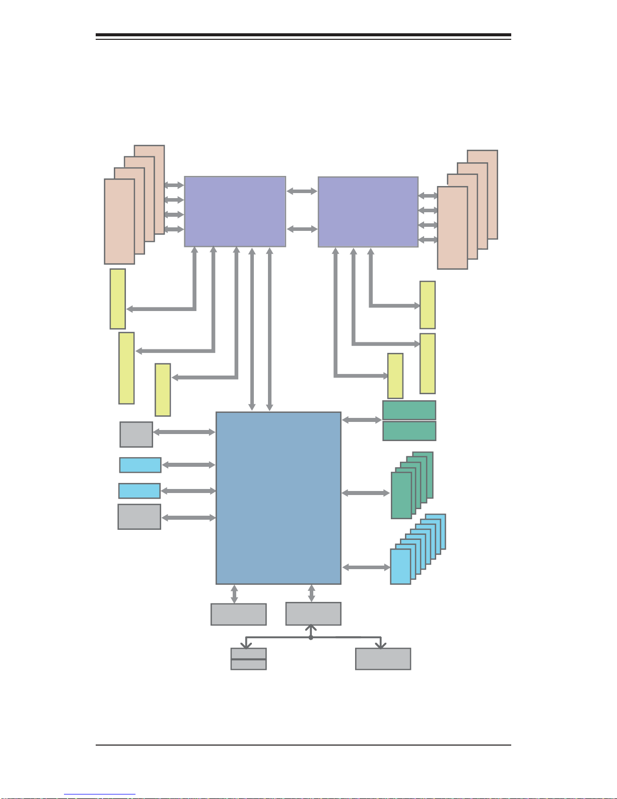
features of the X9DA7/X9DAi. (See Figure 1-1 for a block diagram of the chipset).
Processors
The X9DA7/X9DAi supports single or dual Intel E5-2600 processors in LGA 2011
sockets. Please refer to the serverboard description pages on our web site for a
complete listing of supported processors (www.supermicro.com).
Memory
The X9DA7/X9DAi has sixteen DIMM slots that can support up to 512 GB of
registered/unbuffered ECC DDR3-1600/1333/1066/800 LRDIMMs (load-reduced
DIMMs). See Chapter 5 for details.
Onboard SAS (7047A-73 only)
The X9DA7 includes an LSI 2308 SAS controller, which supports eight SAS2 ports.
The hot-swap SAS drives are connected to a backplane that provides power, bus
termination and confi guration settings.
Note: The operating system you use must have RAID support to enable the hot-swap
capability and RAID function of the SAS drives. RAID 0, 1, 5 and 10 are supported (RAID
5 is not supported with Linux OS). Refer to the following ftp site for setup guidelines
<ftp://ftp.supermicro.com/driver/SAS/LSI/LSI_SAS_EmbMRAID_SWUG.pdf>.
SATA
A SATA controller is integrated into the chipset to provide a Serial ATA subsystem
that supports RAID 0, 1, 5 and 10 (RAID 5 is not supported with Linux OS). The
SATA drives are hot-swappable units. The 7047A-73 (X9DA7) supports two SATA
3.0 and four SATA 2.0 ports while the 7047A-T (X9DAi) supports six SATA 3.0 and
four SATA 2.0 ports.
Note: The operati ng system yo u use must h ave R AID su ppor t to e nable t he hotswap capability and RAI D function of the Serial ATA drives.
PCI Expansion Slots
The X9DA7/X9DAi has three PCI-E 3.0 x16, two PCI-E 3.0 x8 and one PCI-E 3.0
x4 slots. Note that the expansion slots are enabled with CPUs, therefore if a CPU
1-2

Chapter 1: Introduction
socket is empty the PCI slos associated with it cannot be used. See Chapter 5 for
details.
Onboard Controllers/Ports
The color-coded I/O ports include one COM port, six USB 2.0 ports, PS/2 mouse and
keyboard ports, two Gb Ethernet ports and six HDA (High Defi nition Audio) ports.
1-3 Chassis Features
The SC743TQ-1200B-SQ is an ATX form factor chassis that can be used as a tower
or mounted in a 4U rackmount confi guration. The following is a general outline of
the main features of the SC743TQ-1200B-SQ chassis.
System Power
The 7047A-73/7047A-T features a single 1200W power supply. This power supply
unit has been designed to operate at a low noise level to make it ideal for use in
a workstation environment.
SAS Subsystem
The SC743TQ-1200B-SQ chassis was designed to support eight SAS or SAT A hard
drives , whic h are hot- swapp able uni ts. (SAS is w ith 70 47A-73 only).
Front Control Panel
The control panel on the SuperWorkstation 7047A-73/7047A-T provides you with
system monitoring and control. LEDs indicate system power, HDD activity, network
activity, overheat conditions and power supply failure. A main power button and a
system reset button are also included.
Note: the power supply fail LED indicates the power supply fan has failed.
Cooling System
The SC743TQ-1200B-SQ chassis has an innovative "Super Quiet" cooling design
that provides suffi cient cooling at very low noise level - ideal for a workplace envi-
ronment. The chassis includes two 8-cm hot-plug PWM (Pulse Width Modulation)
system cooling fans located in the middle of the chassis. A 9-cm PWM exhaust fan
is also located at the rear of the chassis.
1-3
SuperWorkstation 7047A-73/7047A-T User's Manual
Figure 1-1. Intel C600 Chipset:
System Block Diagram
Note: This is a general block diagram. Please see Chapter 5 for details.
#1-4
#1-3
#1-2
#1-1
DDR3
800/1066/1333
PCI-E X16 G3
SLOT 3
PCI-E X16
PCI-E X4 G3
SLOT 2
PCI-E X4 in x8
LAN
82580
PCI-E x16 G3
SLOT 1
PCI-E X16
PCI-E X4
LGA 2011-R
8 SNB CORE
DDR-III
#1
#2
#3
DMI2
4GB/s
LANE1/2/3/4
DMI2
PCI-E X4 G3
DMI2
P0
P1
QPI
8GT/s
QPI
8GT/s
LGA 2011-R
P1
8 SNB CORE
P0
#3
#2
PCI-E x8 G3
SAS
DDR-III
#1
PCI-Ex8 G3
PCI-Ex16 G3
PCI-E x8
SAS
Ports#0~3
SAS
Ports#4~7
PCI-E x8
PCI-E x16
SLOT 4
#2-4
#2-3
#2-2
#2-1
DDR3
800/1066/1333
SLOT 6
SLOT 5
USB 3.0
USB 3.0
AOCWIPMI
PCI-E X1
PCI-E X1
PCI
LANE7
LANE8
SPI
MS
KB
PCH
C600-A
SSB-D
SIO
W83627
3.0 Gb/S
6.0 Gb/S
for Port 0/1
USB 2.0
COM1
External
#0~#5
SATA
USB
#0~#7
1-4

Chapter 1: Introduction
1-4 Contacting Supermicro
Headquarters
Address: Super Micro Computer, Inc.
980 Rock Ave.
San Jose, CA 95131 U.S.A.
Tel: +1 (408) 503-8000
Fax: +1 (408) 503-8008
Email: marketing@supermicro.com (General Information)
support@supermicro.com (Technical Support)
Web Site: www.supermicro.com
Europe
Address: Super Micro Computer B.V.
Het Sterrenbeeld 28, 5215 ML
's-Hertogenbosch, The Netherlands
Tel: +31 (0) 73-6400390
Fax: +31 (0) 73-6416525
Email: sales@supermicro.nl (General Information)
support@supermicro.nl (Technical Support)
rma@supermicro.nl (Customer Support)
Asia-Pacifi c
Address: Super Micro Computer, Inc.
4F, No. 232-1, Liancheng Rd.
Chung-Ho 235, Taipei County
Taiwan, R.O.C.
Tel: +886-(2) 8226-3990
Fax: +886-(2) 8226-3991
Web Site: www.supermicro.com.tw
Technical Support:
Email: support@supermicro.com.tw
Tel: 886-2-8226-5990
1-5

SuperWorkstation 7047A-73/7047A-T User's Manual
Notes
1-6

Chapter 2: Installation
Chapter 2
Installation
2-1 Overview
This chapter provides a quick setup checklist to get your SuperWorkstation 7047A73/7047A-T up and running. Following these steps in the order given should enable
you to have the system operational within a minimum amount of time. This quick
setup assumes that your system has come to you with the processor and memory
preinstalled. If your system is not already fully integrated with a serverboard, processor, system memory etc., please turn to the chapter or section noted in each step
for details on installing specifi c components.
The 7047A-73/7047A-T may be employed either as a tower or mounted in a rack as
a 4U rackmount chassis. If using it as a tower unit, please read the Server Precau-
tions in the next section before using the system for the fi rst time.
2-2 Unpacking the System
You should inspect the box the system was shipped in and note if it was damaged
in any way. If the system itself shows damage you should fi le a damage claim with
the carrier who delivered it.
Decide on a suitable location for the SuperWorkstation. It should be situated in
a clean, dust-free area that is well ventilated. Avoid areas where heat, electrical
noise and electromagnetic fi elds are generated. You will also need it placed near
a grounded power outlet. Be sure to read the Rack and Server Precautions in the
next section.
2-3 Preparing for Setup
The box the system was shipped in may include two sets of rail assemblies, two
rail mounting brackets and mounting screws needed for installing the system into
a rack (optional kit). Follow the steps in the order given to complete the installation
process in a minimum amount of time. Please read this section in its entirety before
you begin the installation procedure outlined in the sections that follow.
2-1
SuperWorkstation 7047A-73/7047A-T User's Manual
!
!
Choosing a Setup Location
• Leave enough clearance in front of the rack to enable you to open the front door
completely (~25 inches) and approximately 30 inches of clearance in the back
of the rack to allow for suffi cient airfl ow and ease in servicing.
• This product is not suitable for use with visual display work place devices
acccording to §2 of the the German Ordinance for Work with Visual Display
Units.
Warnings and Precautions!
Rack Precautions
• Ensure that the leveling jacks on the bottom of the rack are fully extended to
the fl oor with the full weight of the rack resting on them.
• In single rack installation, stabilizers should be attached to the rack. In multiple
rack installations, the racks should be coupled together.
• Always make sure the rack is stable before extending a component from the
rack.
• You should extend only one component at a time - extending two or more si-
multaneously may cause the rack to become unstable.
Server Precautions
• Review the electrical and general safety precautions in Chapter 4.
• Determine the placement of each component in the rack before you install the
rails.
• Install the heaviest server components on the bottom of the rack fi rst, and then
work up.
• Use a regulating uninterruptible power supply (UPS) to protect the server from
power surges, voltage spikes and to keep your system operating in case of a
power failure.
2-2

Chapter 2: Installation
• Allow the hot plug SAS/SATA drives and power supply modules to cool before
touching them.
• Always keep the rack's front door and all panels and components on the servers
closed when not servicing to maintain proper cooling.
Rack Mounting Considerations
Ambient Operating Temperature
If installed in a closed or multi-unit rack assembly, the ambient operating temperature of the rack environment may be greater than the ambient temperature of the
room. Therefore, consideration should be given to installing the equipment in an
environment compatible with the manufacturer’s maximum rated ambient temperature (Tmra).
Reduced Airfl ow
Equipment should be mounted into a rack so that the amount of airfl ow required
for safe operation is not compromised.
Mechanical Loading
Equipment should be mounted into a rack so that a hazardous condition does not
arise due to uneven mechanical loading.
Circuit Overloading
Consideration should be given to the connection of the equipment to the power
supply circuitry and the effect that any possible overloading of circuits might have
on overcurrent protection and power supply wiring. Appropriate consideration of
equipment nameplate ratings should be used when addressing this concern.
Reliable Ground
A reliable ground must be maintained at all times. To ensure this, the rack itself
should be grounded. Particular attention should be given to power supply connections other than the direct connections to the branch circuit (i.e. the use of power
strips, etc.).
2-3
SuperWorkstation 7047A-73/7047A-T User's Manual
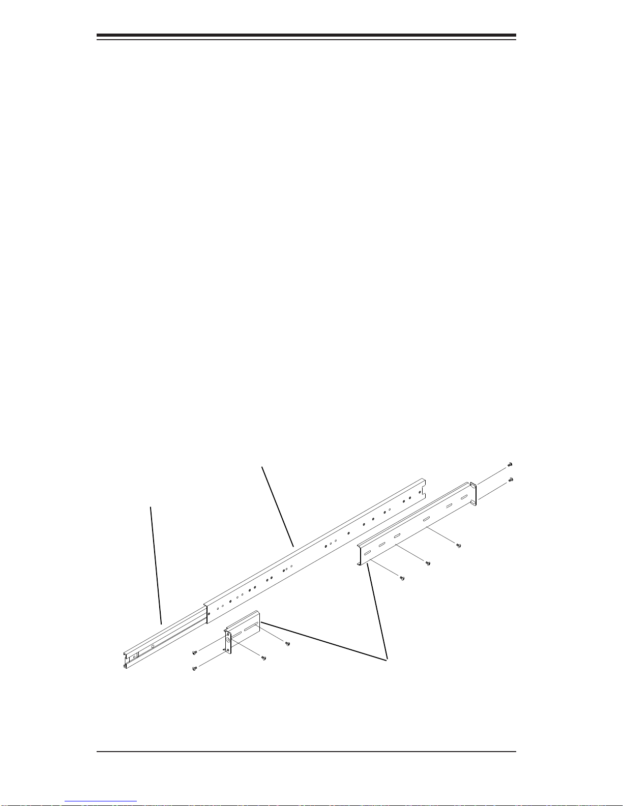
Inner rail
Outer rail
Rail brackets
2-4 Installing the System into a Rack
This section provides information on installing the system into a rack unit. Rack
installation requires the use of the optional rackmount kit.
There are a variety of rack units on the market, which may mean the assembly
procedure will differ slightly. The following is a guideline for installing the system
into a rack with the rack rails provided in the rackmount kit. You should also refer
to the installation instructions that came with the rack unit you are using.
Identifying the Sections of the Rack Rails
The optional rackmount kit includes two rack rail assemblies. Each of these assemblies consist of three sections: an inner fi xed chassis rail that secures to the
chassis, an outer rack rail that secures directly to the rack itself and two rail brackets,
which also attack to the rack (see Figure 2-1.) The inner and outer rails must be
detached from each other to install.
To remove the inner chassis rail, pull it out as far as possible - you should hear a
"click" sound as a locking tab emerges from inside the rail assembly and locks the
inner rail. Depress the locking tab to pull the inner rail completely out. Do this for
both assemblies (one for each side).
Figure 2-1. Identifying the Sections of the Rack Rails
2-4
Chapter 2: Installation
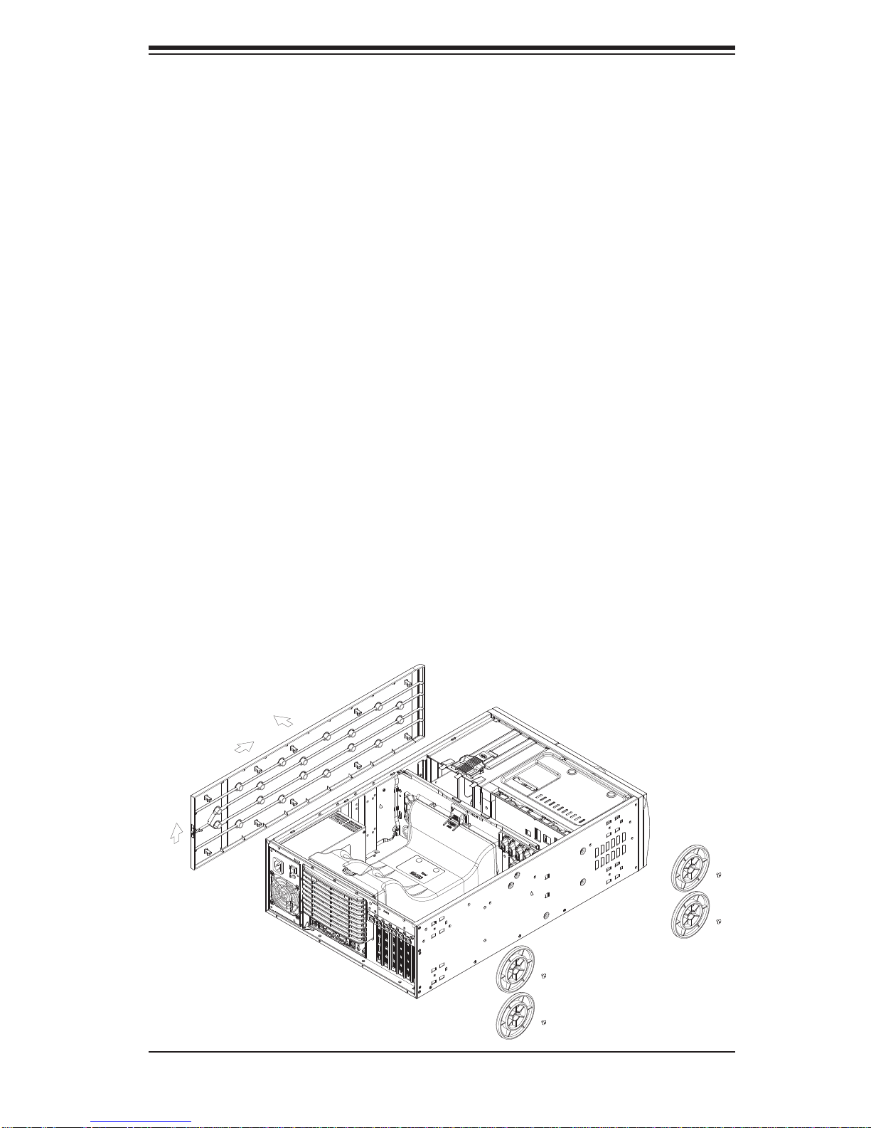
Installing the Chassis Rails
You will need to remove the top cover and the feet to add rack rails to the chassis.
First, remove the top and right covers (top and left covers when standing as a tower
chassis) by fi rst removing the screws that secure them to the chassis. Depress the
button on the top (side if tower) of the chassis to release the cover and then pull
the cover off. Then unscrew the four feet and remove them from the chassis (see
Figure 2-2).
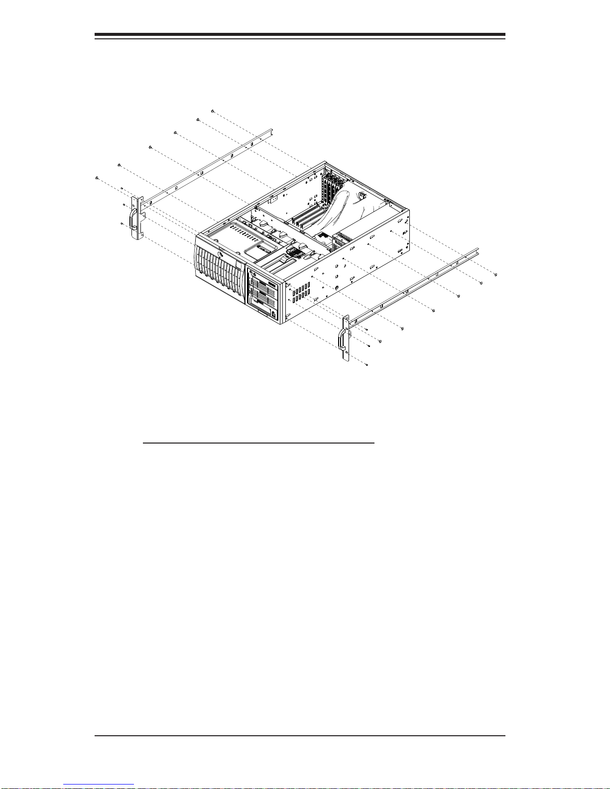
You can now attach rack rails to the top and bottom (now the sides) of the chassis.
First add the rack handles. Then position the inner chassis rail sections you just
removed along the side of the chassis making sure the screw holes line up. Note
that these two rails are left/right specifi c. Screw the rail securely to the side of the
chassis (see Figure 2-3). Repeat this procedure for the other rail on the other side
of the chassis. You will also need to attach the rail brackets when installing into a
telco rack.
Locking Tabs: As mentioned, the chassis rails have a locking tab, which serves
two functions. The fi rst is to lock the system into place when installed and pushed
fully into the rack, which is its normal position. Secondly, these tabs also lock the
system in place when fully extended from the rack. This prevents the system from
coming completely out of the rack when you pull it out for servicing.
Figure 2-2. Preparing to Install the Chassis Rails
2-5
SuperWorkstation 7047A-73/7047A-T User's Manual
Figure 2-3. Installing the Rails to the Chassis
Installing the Rack Rails
Determine where you want to place the SuperWorkstation 7047A-73/7047A-T in the
rack. (See Rack and Server Precautions in Section 2-3.) Position the fi xed rack rail/
sliding rail guide assemblies at the desired location in the rack, keeping the sliding
rail guide facing the inside of the rack. Screw the assembly securely to the rack
using the brackets provided. Attach the other assembly to the other side of the rack,
making sure both are at the exact same height and with the rail guides facing inward.
2-6
Chapter 2: Installation
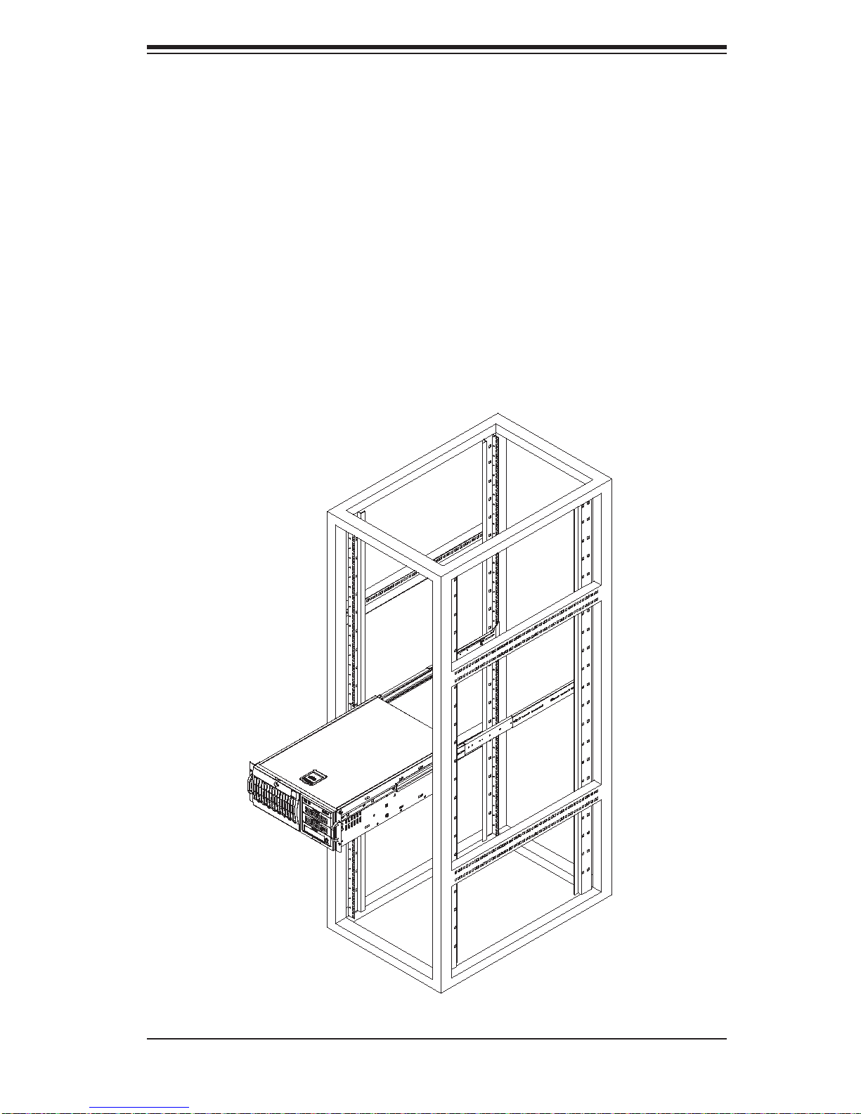
Installing the System into the Rack
You should now have rails attached to both the chassis and the rack unit. The next
step is to install the system into the rack. You should have two brackets in the rack
mount kit. Install these fi rst keeping in mind that they are left/right specifi c (marked
with "L" and "R"). Then, line up the rear of the chassis rails with the front of the rack
rails. Slide the chassis rails into the rack rails, keeping the pressure even on both
sides (you may have to depress the locking tabs when inserting).
When the system has been pushed completely into the rack, you should hear the
locking tabs "click". Finish by inserting and tightening the thumbscrews that hold
the front of the chassis to the rack (see Figure 2-4).
Figure 2-4. Installing the System into a Rack
2-7

SuperWorkstation 7047A-73/7047A-T User's Manual
Notes
2-8
Chapter 3: System Interface
Chapter 3
System Interface
3-1 Overview
The control panel on the 7047A-73/7047A-T has several LEDs and two buttons.
There are also two LEDs on each hard drive carrier. These LEDs keep you constantly informed of the overall status of the system and the activity and health of
specifi c components.
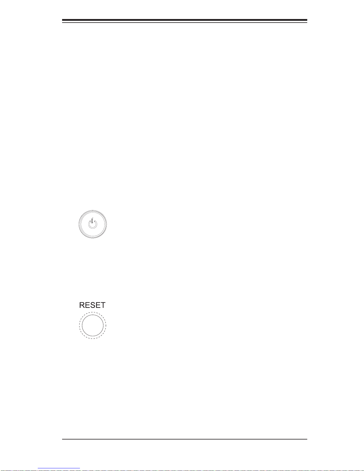
3-2 Control Panel Buttons
There are two push-buttons located on the front of the chassis: a power on/off
button and a reset button.
Power
This is the main power button, which is used to apply or turn off the main system
power. T urning off system power with this button removes the main power but keeps
standby power supplied to the system.
Reset
Use the reset button to reboot the system.
3-1
SuperWorkstation 7047A-73/7047A-T User's Manual
3-3 Control Panel LEDs
The control panel located on the front of the SC743TQ-1200B-SQ chassis has
six LEDs that provide you with critical information related to different parts of the
system. This section explains what each LED indicates when illuminated and any
corrective action you may need to take.
Power
Indicates power is being supplied to the system's power supply. This LED should
normally be on when the system is operating.
HDD
This LED indicates SAS (on the 7047A-73 only) or SA T A drive activity when fl ashing.
1
NIC1
Indicates network activity on LAN1 when fl ashing.
2
NIC2
Indicates network activity on LAN2 when fl ashing.
Overheat/Fan Fail
When this LED fl ashes, it indicates a chassis fan failure. When on continuously it
indicates an overheat condition, which may be caused by cables obstructing the
3-2
Chapter 3: System Interface
airfl ow in the system or the ambient room temperature being too warm. Check the
routing of the cables and make sure all fans are present and operating normally.
You should also check to make sure that the chassis covers are installed. Finally,
verify that the heatsinks are installed properly (see Chapter 5). This LED will remain
fl ashing or on as long as the indicated condition exists.
Power Fail
Indicates a power supply fan has failed. The power supply module has a redundant
backup fan that will increase its rpm to compensate, but the power module should
be replaced as soon as it's convenient.
3-4 Drive Carrier LEDs
Note: the LEDs of some drive carriers may not function depending on the number
of drives that are supported by the serverboard and/or backplane.
• Green: When illuminated, the green LED on the front of the hard drive carrier
indicates drive activity. A connection to the drive backplane enables this LED to
blink on and off when that particular drive is being accessed.
• Red: The backplane activates the red LED to indicate a drive failure. If one of
the hard drives fail, you should be notifi ed by your system management soft-
ware. Please refer to Chapter 6 for instructions on replacing failed hard drives.
3-3

SuperWorkstation 7047A-73/7047A-T User's Manual
Notes
3-4
Chapter 4: System Safety
!
Chapter 4
System Safety
4-1 Electrical Safety Precautions
Basic electrical safety precautions should be followed to protect yourself from
harm and the SuperWorkstation 7047A-73/7047A-T from damage:
• Be aware of the locations of the power on/off switch on the chassis as well
as the room's emergency power-off switch, disconnection switch or electrical
outlet. If an electrical accident occurs, you can then quickly remove power from
the system.
• Do not work alone when working with high voltage components.
• Power should always be disconnected from the system when removing or in-
stalling main system components, such as the serverboard, memory modules
and the DVD-ROM and fl oppy drives. When disconnecting power, you should
fi rst power down the system with the operating system. The unit has more than
one power supply cord. Disconnect both power supply cords before servicing
to avoid electrical shock.
• When working around exposed electrical circuits, another person who is familiar
with the power-off controls should be nearby to switch off the power if necessary.
• Use only one hand when working with powered-on electrical equipment. This
is to avoid making a complete circuit, which will cause electrical shock. Use
extreme caution when using metal tools, which can easily damage any electrical
components or circuit boards they come into contact with.
• Do not use mats designed to decrease electrostatic discharge as protection from
electrical shock. Instead, use rubber mats that have been specifi cally designed
as electrical insulators.
• The power supply power cord must include a grounding plug and must be
plugged into grounded electrical outlets.
4-1
SuperWorkstation 7047A-73/7047A-T User's Manual
!
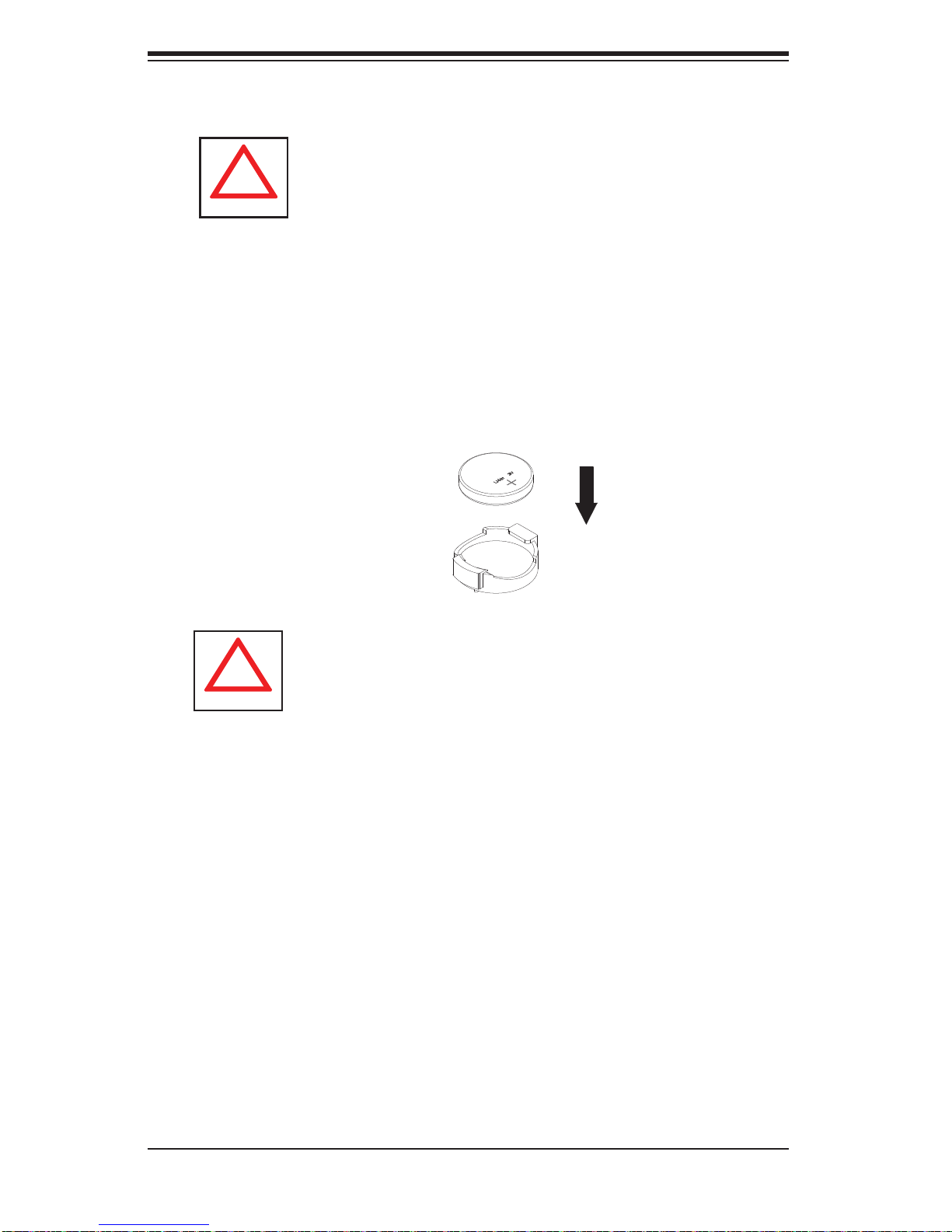
• Serverboard Battery: CAUTION - There is a danger of explosion if the onboard
battery is installed upside down, which will reverse its polarities (see Figure 4-1).
This battery must be replaced only with the same or an equivalent type recommended by the manufacturer (CR2032). Dispose of used batteries according to
the manufacturer's instructions.
• DVD-ROM Laser: CAUTION - this server may have come equipped with a
DVD-ROM drive. To prevent direct exposure to the laser beam and hazardous
radiation exposure, do not open the enclosure or use the unit in any unconventional way.
• Mainboard replaceable soldered-in fuses: Self-resetting PTC (Positive Tempera-
ture Coeffi cient) fuses on the mainboard must be replaced by trained service
technicians only. The new fuse must be the same or equivalent as the one
replaced. Contact technical support for details and support.
4-2 General Safety Precautions
Follow these rules to ensure general safety:
• Keep the area around the SuperWorkstation 7047A-73/7047A-T clean and free
of clutter.
• The 7047A-73/7047A-T weighs approximately 64 lbs (29.1 kg.) when fully
loaded. When lifting the system, two people at either end should lift slowly with
their feet spread out to distribute the weight. Always keep your back straight
and lift with your legs. Don't use the handles (if installed) to lift the chassis; the
handles should only be used to pull the server out of the rack.
• Place the chassis top cover and any system components that have been re-
moved away from the system or on a table so that they won't accidentally be
stepped on.
• While working on the system, do not wear loose clothing such as neckties and
unbuttoned shirt sleeves, which can come into contact with electrical circuits or
be pulled into a cooling fan.
• Remove any jewelry or metal objects from your body, which are excellent metal
conductors that can create short circuits and harm you if they come into contact
with printed circuit boards or areas where power is present.
4-2
Chapter 4: System Safety
!
• After accessing the inside of the system, close the system back up and secure
it to the rack unit with the retention screws after ensuring that all connections
have been made.
4-3 ESD Precautions
Electrostatic discharge (ESD) is generated by two objects with different electrical
charges coming into contact with each other. An electrical discharge is created to
neutralize this difference, which can damage electronic com ponents and printed
circuit boards. The following measures are generally suffi cient to neutralize this
difference before contact is made to protect your equipment from ESD:
• Use a grounded wrist strap designed to prevent static discharge.
• Keep all components and printed circuit boards (PCBs) in their antistatic bags
until ready for use.
• Touch a grounded metal object before removing the board from the antistatic
bag.
• Do not let components or PCBs come into contact with your clothing, which may
retain a charge even if you are wearing a wrist strap.
• Handle a board by its edges only; do not touch its components, peripheral chips,
memory modules or contacts.
• When handling chips or modules, avoid touching their pins.
• Put the serverboard and peripherals back into their antistatic bags when not
in use.
• For grounding purposes, make sure your computer chassis provides excellent
conductivity between the power supply, the case, the mounting fasteners and
the serverboard.
4-3
SuperWorkstation 7047A-73/7047A-T User's Manual
!
!
4-4 Operating Precautions
Care must be taken to assure that the chassis cover is in place when the system
is operating to assure proper cooling. Out of warranty damage to the system can
occur if this practice is not strictly followed.
Figure 4-1. Installing the Onboard Battery
LITHIUM BATTERY
BATTERY HOLDER
Please handle used batteries carefully. Do not damage the battery in any way; a
damaged battery may release hazardous materials into the environment. Do not
discard a used battery in the garbage or a public landfi ll. Please comply with the
regulations set up by your local hazardous waste management agency to dispose
of your used battery properly.
4-4
 Loading...