

Superior ST-1 Series, ST-3840-1 Installation Instructions Manual

Insfallation
lnsfructions
For Superior's
ST- 1 Series
Fireplace
Model
ST-3840-1
This Installation manual will enable you to make a
sale,
efcient and dependable instalbtion 01 your
lireplaca and chimney system. Please read and
understandthminst~dionsbefuebeginning
installation.
Da
not alter or modify the mnstrudion of the fire
placeor h'smrnponents underany cirarmstances.
Any modification or alleralion of the fireplace sys-
bbl
no1
tem; including
ney wmponents and accessories, may
warranty, listings and approvals of this system and
mu!d result in
installalion.
PLEASE RETAIN THIS MANUAL FOR
FUTUREREFERENCE
limitedtothefireplace,chim-
an
unsale and potentially dangerous
wid
you1
the

IMPORTANT!
'LEASE
READ
AND
UNDERSTAND
THESE RULES TO FOLLOW FOR
SAFETY
1.
Before starting your lireplacs installation, read
installation instructions wefully to
these
you
undersland
Failure
lo
,&low
resuhing
elly damage.
2
Ahvays check your local building mdes. The
installation must
national coded and regulations.
3.This model lireplacemust
rior Model
Thru-flow Chimney Syslem only. This system is
intended for use
Chimney must ahuays vent to the ouiside ol the
building.
4.
thebuild-vpofsoat and creosote, inspect and dean
the
cally during the heating season.
5.
chemical chimney cleaners or Rame
your lireplaca.
TFIO
To ensure asafe lireplaca system and to prevent
lireplacs and chimney priorto use and panodi-
Use solid fuel only.
completely
them
muld
cause a fireplace
in
serious
mmpiy wilh all local, regional and
be
installed with Supe-
(10'
(2Mmm) inside diameter)
as
a residenlial type appliam.
DO
NOT use artificial bgs,
and in
miorants in
be
sure
prop
12
Always ensure that an adequate supply ol re
placement mmbustion air frwn the outside ol he
house is
accessble
I
tion. ~ireohcss mnsume iaroewlumes of airdur- I ~adorv reoresentative to ensure safe condition.
ing thec&bustionprocess.in theeventthe home
is tichtlv sealed with modern enemy efficient fea-
lures. ~uparior's optional mmbugibn air
not provide all the air required to
1.h.
Supecar is not responsible for any smoking
wlated problems that may resun from the Idol
adequate mmbuslian air. It is the responsibility of
the builderlmntraaor to ensure that adequale
mmbustion air has been provided lor the fireplace.
13.
DO
NOT use a %'lace
products not sphfied herein by Superior for use
wilh this fireplace.
14.
Superior Fireplacecompany doesnot warranty
'smoke free' operation nor are we
inadequate
systems,
quate dimney heights, adverse wind mndilions
andlor unusual environmental lactors or conditions
beyond our control.
15.
place, chimney mmponent or any accsssories.
supplied by
generai mnslructbn mndiiicns, inade
Never, under any circumstances, install a rire
TYPICAL INSTALLATION
tothe lire to
system draft caused by mechanical
Superiir FireplaosCompany. lhal has
smrt
minbus-
ki
suppwl mmbus-
insert
Or
any
rqnsible for
may
Other
-
visblewsuspededphysical damage asaresuhol
handling w transportation. These items shouid be
ihmcled bv a Suoerior distributor w aualified
Whenin doubt, consuR your Superiordistrbutor.
TOOLS AND BUILDING SUPPLIES
NORMALLY REQUIRED
w
Tools should
Phiilips screwdriver
Hammer
Saw
Level
Measuring
plumb
Electric drill and bids
Pliers
Square
Building supplies:
Framing materials
Wall finishing materials
Caulking materials
(nonmmbustible)
Fireplace surround and
hearth extension
(nonmmbustible)
Indude:
andlor Sabersaw
!ape
line
materials
6.
DO NOT
use
hard w mal under any circum-
SlanceS.
7.
NEVER
use gasoline. gasahnetype lantern hiel.
kerosene, charmal lighter fluid, or any liquids to
start w'heshen up'alire in lhis lireplam, Keep any
llammable liquids a safe distance hom the fire
place.
8.NEVER leavechildren unattended when there
a lire burning in the lireplace.
9.
Aiways
keq
Rue damper open when heat is
present in the
10.
Belore servicing, allow the lireplace to mol.
Ahvays shut of1 any gas lo the lireplaca whib
working on
11. This fireplace is
primary or secondary heat
sign is foremost intended lor archiiectural. decorating and aesthelic qualities.
fireplace.
g.
This will prevent any possible burns.
not intended to be used as a
snurm. ll's unique de
is
Ffgum
NOTE:
1
CUG?AUS6
kLffiTRATKXIS
NOTTOSULE

PRECAUTIONS
Nole: Thew, firepbm systems are nol difficuk
insiall. However,
recommended that
certified Tradesman' familiar with mmonly accepted fireplace
as well as prevailing
The most important areas
installatian ol ladory-built fireplaces are clear-
the
ances to
of component
theproperuseolaccessory equipment suppled by
Superior and the
finishing materials applied to the wall surrounding
the fireplace, hearth
Each
01
these topics will
detail
thrwghout
your
special
installalion.
WARNING: WHEN INSTALLING THIS FIREPLACE IN CANADA, THE CHIMNEY AIR
I
MUST BElNSTALLEDPERWARtJOCK HERSiY
I
INTERNATIONAL. INC. -STING.TrllS IS NOT A
U.L. LISTED INSTALLATION
WARNING: WHEN
*
PLACE IN
AIR SPACE FROMTHE CHIMNEY IS Z(51MM).
INTRODUCTION
General
in
the Interest of safety,
lhe Installer
installalion and safety techniques
local codes.
mmbustible materiais, prow assembly
pas, height olthechimney sptem,
lechniques employed in utilizing
exlensions and wall shields.
this
manual. Please glve each
anention as you progress with your
iNSTALLlNG THIS FIRE-
CANADA,THE REQUIRED hllNlMUM
Information
be
of concern dealing whh
be
mvered in thorough
il
a qualifd
KIT
This lire~lace svslem is inlended lor inslallation in
accordaceinrhthe National Fire Protection Slandardforchimneys. lirepiaces andxriid luel burning
to
appliances: NFPA 211 and in
is
mdes such as the BOCA Basic~National Codes.
or
the
Standard Mechanical Code. Unilorm Building
Codes andlor the Canadian National Codes.
FAILURETOUSEPARTS MANUFACTUREDBY
SLPEROR FIREPLACE COMFANY OR
MATEFIALSDESCR BEDIN-HISMANUALMAY
F
CREATE A
RIOR S
The
ST-1 system Consists of four 'sub-systems':
1.
The Fireplace and Door Assemblies
2.
The Chimney and Termination
3.
The Optionai Combustion Air Kit
4.
Chimney Air Kit (Canada Only)
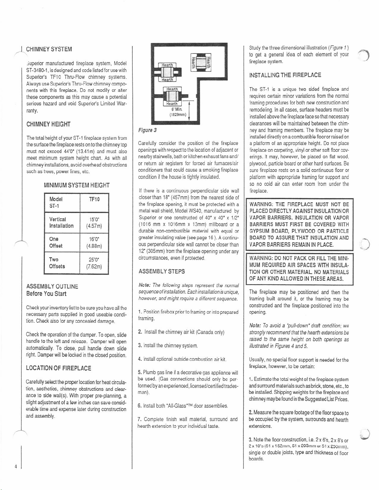
CLEARANCES AND HEIGHT
REQUIREMENTS
ST-1 Series may
The
mnstrudion materials.' The mmbustion air lot.
lirestop
ings) may be placed directly on or agalnst normal
mnstrudion material'. The chimney requires a
minimum 1'
mmbustiMes. A combustible mantel may
stalled 12' above the lireplace opening as per
NFPA 211.
mum is
RE rlAZARD AhD VOID SUPE-
LIMITED WARRANTY.
be
spacer
and rwf llashings (not chase llash-
(25mm)" (See *'Note) air space to
Seclion
7-3.3.3.
14'(356mm) ahave lhe opening.
acmrdance with
placed on or near normal
In Canada the mini-
VARI.
be
in.
FRAMING
As many
tins
piam. The lollowing illustrations depid these van
ationsol wall enclosures. Several
may
etc.
WALL
VARIATIONS
as
six (6) different lramed wall mnfigura
on
be
mnstruded lo endow
incorporalebaokshelves, wmdstoragetax~
Parallel
Walls
ha
ST-1
ol
thesedesign
lire
+mk
"v'
Type
Walls
I
8,
'H"
Typ
Walls
I
I
ST-1 Series is a nominal heat circulaling. Iwo
The
sided fireplace with standard glass dwn. A steei
bar
grateis also included whh the ST-1 to properly
position the fire. An oulside wmbustion air kit,
Modei CAK-4, is available as optional equipment.
Note: lllusirations shown reflect 7ypical'installalions
wrth
nominal
dimensions
and framing referenm only. Actual instaliatbns
may vary due to individual design preferences.
However, alwaysmaintain minimum clearances lo
mbustible materials anddo not vbkte any
ci(c
installation requirements.
The ST-1 Series fireplace has been tested and
WarnockHersey International, Inc.to U.L.
listed by
127standard lor U.S. installationsand U.L.C.S610
standard lor Canadian inslaliations. This unit is
intended to be installed in
buildings of conventional
bile homes.
and are for desrgn
spe
residenlial homes and
mnstrudwn, not in mo-
fireplaceandchimney must be enclosed when
The
installed in or passing through a living area where
combustiblesorpeoplemaycome
imponant toprevent possbk personal injury
This is
or fire hazard.
'Construnion Materials:
framing materials
plywood
panicle board
.
flwring
.
milboard
dry wall
.paneling
etc.
For questions,
nor Fireplace Company. Special restrictions apply
to the
walls
"Note:
required when Installing
Canada.
piease
call
Iron! and lacing of Ihe lireplace and nearby
(See
pages 16 and 17
Z"(51mmJ
HOE:
DUCALLIS6
airspace
IUUSTRATlONS
in mntad with it.
yourdistrbutor or Supe
).
10
comburtlbles
Mods1
ST-3840-1
NOTTOSCKE
In
AJmTL
"L"
Typo
Wallr
=DzDE
'TType
Walls

A
4.
Use this intormation
ing mde to determine
port.
CAUTION: DO NOT BLOCK THE HEAT CIRCULATING AIR INLETS AND OUTLETS.
MAY RESULT IN A POTENTIAL
It you plan lo raise the fireplace and heaflh exten.
sion, build lhe ptattorm assembly then psition
fireplace and heanh extension on top. Secure the
platform to the
TO
INSTALL:
1.
Slide fireplace into prepared lraming or
Slep
position
fireplacein its final position and frame later.
Slep
2.
Insen the metalsalety strips, packaged with
Ihe fireplace, benealh the
(figures4
1'
Note: Salety strips are not required when
rests on a non-combustible flour.
and5
(25mm) tor continual coverage ol the Boor.
lb'(l3mml
Clunner
To
Bclh
Sides
and
consult your local bud-
if
you need additional sup
FIRE HAZARD.
tbor to prevent possible shining.
firepbce
).The
safety strips should overlap
>
Hosrth
Eaenwon
$k:;
DOING
as
illustrated
firsplace
SO
Flgure
6
Metal
Safsty
Slrip
Figure
7
Nole:
The
'7
rype
safety strip is not supplied by
Superior.
3.
Reler to fireplace drawings and
Step
tionsonpages6 and7 forlraming dimensionsand
details. Fake
top oi
header may be positioned directly on
the lirephce spacers.
specifics-
Step
5.
Fireplace should be securedto side fram-
8d
U.L.
*?\
nails
be-
lbted
ing members using nailing flanges. Use
(Figure
9).
Flgure
9
Note: The nailing flange and the area direah
hind the naiing Rangeare exempt from the fireplace
clearances
label.
FOR
PROCEED
Note:
installation.
Step6.Attachthe4'(102mm)
4
air
transition,usvlgthetwo
transition (Figure 10).
described
CANADIAN INSTALLATIONS,
wrrn
W.H.I.
kit
over the grill on the dosed end of the
on the fireplace dearanca
STEPS
e-9.
#sled only. This k not a
mllarhomtheCAK-
(2)
screwsmountedonlhe
Met4
Salon(
Str>pr
Figure
4
PMorm
Hdanh
Exlen$ion
bpF&k
Flgure
5
Note: Install the hearth extension only
trated.
Thesafety strips should
lhe fireplace
support k used to elevate the firqlaca above the
fbor,
used to protect the front surface of the wwd supPort
sion (Figures
tacked down to prevent possible movemen!.
2'
a'2typesaletyst<pshouid befabricdtedand
as
weil
as
6and7). Thesalety stripsshould
exlend m lrontand sidesof
(51mm). In the even( a woalen
the floor beneath the health exten-
Hssnh
Enension
%or
Meld
Safely
Slrips
as
illus-
be
IMPORTANT: UNDER NO CIRCUMSTANCES
CAN THE FIREPLACE TOP SPACERS BE
REMOVEDOR MODIFIED.DONOTNOTCHTHE
HEADER TO
PLACE TOP SPACERS.
Step 4.Fireplacernay besecured tothelloor. Bend
down four
iireplace and secure wdh na~is (Figure
Flgure
NOTE:
FIT
LOWER THAN THE FIRE-
(3)
anchortabs located at thebase ofthe
8
DIAUIAUSa
LLUmATDNS
NOTTOSCME
-
~
8).
~~~
-
Figure
10
Slep7.Connedthe4'(102mm)Ctass
mllar(justmounted) wiihthescremprovided in he
hardware
Step8. RoutetheClass 1 duct outthe backorside
wall, up through the
outside wall. The dun should be bcated abave
snow level.
kit.
i
1
1
dudtothe
ceiiing w floor joists to
an

Note: If the fireplace $ instailed againsr an inside
I-.
wall, the Class I duct may be extended into
,entilatedatf~ space at least
fhe anic floor. Secure the duct hod to a vertical
post with the inlet positioned downward. Ensure
nothing blocks the
never terminate higher than the chimney.
Step
9.
'
I
1
Cut or kame hole through !he outside wall
installatun of the dud inlel hood.
lor the
(1 14mm) diameter hole issuflident. Feed iheloose
end aflhe flexible duct through the hole
Inlet Hcod and attach lo mllar on lnlet Hood using
Two(2) screws. Insert hood intoopening. securein
placewithnailsdf~enthrough
Seal with non-combustible watemroof silicon tw
cauking. It additional duct is needed, use Class 1
metdlic dud.
INSTALLING THE CHIMNEY SYSTEM
hood opening. lhe dud must
1B'
(457mm) above
A
cul
holesinhaodllange.
4
112'
lor the
.
,
FIREPLACE SPECIFICATIONS
a
pJ.:.
Figure
(546mm)
-
TCQ
Vlew
12
1.Chedclluedamperforproperqeration.
Step
open, slide handle to lhe
will open automatically. To dose, pull handle down
slide right. Damper will
position.
2.
Using standard mnslnrdian framing tech-
Step
niques,
mnslmct qening lor chimney route up
-
lhroughtheceiling(s)and roolorthrough anoutside
:me.
Framing
musmaintainadequateminimumairspace
dearance at all times.
CALITON: ALLOW MINIMUM
"NOTEJ
TIBLE FRAMING
VERTICAL CR OFFSET ClllMNEY INSTALLA.
TION. ALSO MAINTAIN AIR SPACE ONTOP OF
THE FIREPLACE AS DEFINED BY
ERS AND
(Tan
CHIMNEY AIR SPACE TO COMBUS-
STANDOFFS (FIGURE
1"
A!rSpco
Canada)*
let
and release. Damper
be
lxked in the closed
1"
(25MM)
MEMFERS THROUGHOUT
-
~
THE
11
1.
(SEE
SPAC.
ln
Canada)
To
Figure
13
Accessary Access
End
Vlew
Figure
14
Opposing
End
View
Figom
11
"Note:2"(51mmJ
requlred when Installing Model
6
Canada.
alrspace
lT
Air
to
combustibles
ST-3840-1
Spaca
in
Figure
15
Fmnt
View
 Loading...