

Superior Sofia Instructions For Installation, Use And Maintenance Manual
INSTRUCTIONS FOR
INSTALLATION, USE AND
MAINTENANCE
Pellet Stove
SOFIA
The instruction manual is an integral part of the product.
SUPERIOR
®
English
2
SUPERIOR
®
Dear client,
We thank you for choosing one of our products, the result of technological expertise and continued research in pursuit of a superior
product in terms of safety, reliability and features.
In this manual you will find all the information and useful advice necessary to get the most out of your appliance in total safety.
DT2010001-01
See the guarantee certificate enclosed with the product for the terms, limitations and exclusions.
In line with its policy of constant product improvement and renewal, the manufacturer may make changes without notice.
This document is the property of Gruppo Piazzetta S.p.A.; no part of it may be disclosed to third parties without the written permission of Gruppo
Piazzetta S.p.A. All rights reserved by Gruppo Piazzetta S.p.A..
• This instruction booklet has been prepared by the manufacturer and is an integral part
of the product. In the event of sale or relocation of the product make sure this booklet
accompanies it, since the information contained in it is intended for the purchaser and
for anyone involved in the installation, use and maintenance of the product.
• Read the instructions and the technical information contained in this booklet carefully
before proceeding with installation, use or any repairs.
• The observance of the instructions and technical information in this instruction booklet
guarantees the safety of persons and property; it also ensures more efficient operation
and an increased lifespan.
• Gruppo Piazzetta S.p.A. cannot be held responsible for damage or injury due to failure
to comply with the instructions for installation, use and maintenance given in this
booklet, or due to unauthorised alterations or to the use of other than original spare
parts.
• Appliance installation and use must conform with the manufacturer’s instructions as
well as with European and national legislation and local regulations.
• Installation, electrical connection, checks, maintenance and repairs are operations
which must be carried out exclusively by qualified and authorised personal with
specialised knowledge of the product.
• The wall against which the product is to be placed must not be of wood or any other
flammable material. For correct installation it is also important to comply with the
section entitled “Safety distances”.
• Before installing the product read all instruction booklets relevant to the cladding, the
ventilation kit and any other accessory.
• Check that the floor where the product is to be installed is perfectly level.
• When handling the steel parts of the cladding it is advisable to use clean cotton gloves
to avoid leaving fingerprints that are difficult to remove at first time of cleaning.
• The stove must be assembled by at least two persons.
• Connect the pellet stove to the electricity supply only after it has been connected by
an expert to the flueway.
• The plug at the end of the power cable must be easily accessible after installation.
• Use only recommended wood pellets in the pellet stove (refer to section entitled “FUEL”).
• Never use liquid fuels to light the pellet stove or to relight the embers.
• Ensure that the area where the stove is installed is properly ventilated while the stove
is lit.
• In the event of malfunctioning the fuel supply will be stopped. Restart the stove only
after having eliminated the cause of the malfunction.
• Stop using the product in the event of fault or malfunctioning.
• Do not remove the protective grille from the pellet hopper.
• Any build-up of unused pellets in the burner left over from repeated failed ignitions
must be removed before attempting to light the stove again.
• Stove operation can result in surfaces, handles, flue pipe and glass becoming
extremely hot. When the stove is in operation, only touch these parts if wearing
protective clothing otherwise use suitable tools.
• Because of the build-up of heat on the glass, take care that those who are unfamiliar
with stove operation do not linger near the stove.
• This appliance must not be used by persons (including children) with reduced physical,
sensory or mental capacities, or lack of experience or knowledge unless they are
supervised or instructed on use of the appliance by the person who is responsible for
its safety.
• Creaking may be heard while the stove is in operation or cooling down. This is not to
be considered a defect, but is a consequence of thermal expansion of the component
materials.
• The product you have purchased may different slightly from the one illustrated in this
booklet since the pictures are only given as an indication and not an exact portrayal.
In the event of difficulties or if you are unable to understand the instruction
booklet, contact your local dealer.
Do not place objects which are not heat-resistant on top of the stove or
within the recommended minimum safety area.
Do not open the door while the stove is in operation or operate the stove
when the glass is broken.
EN 14785 Residential space heating appliances fired by wood pellets. Requirements and test methods
EN 832 Thermal performance of buildings - Calculation of energy use for heating - Residential buildings
UNI 10683 Heat generators fired by wood or other solid biofuels - Installation requirements
UNI 10847 Single flue systems for liquid and solid fuel generators - Maintenance and inspection - Guidelines
and procedures
UNI 7129 Gas installations for domestic use fired by mains gas supply. Design, installation and maintenance.
DIN 51731 class HP2 Fuels
ÖNORM M7135 Fuels
CEI EN 60335-1 Safety of household and similar electrical appliances.
Safety. Part 1: General requirements
CEI EN 50165÷1997 Electrical equipment of non-electric appliances for household and similar purposes – Safety
requirements
EN 1856-1 Chimneys - Requirements for metal chimneys - Part 1: System chimney products
EN 1856-2 Chimneys - Requirements for metal chimneys - Part 2: Metal liners and connecting flue pipes
EN 1443 Chimneys – General requirements
IMPORTANT INFORMATION
DT2010208-07
REFERENCE STANDARDS
DT2010209-05
H07022850 / DT2000426 - 00
English
3
SUPERIOR
®
This booklet code H07022850 / DT2000426 Rev. 00 (01/2009) comprises 40 pages.
CONTENTS
DT2010187-00
Section Title Page
1.0 GENERAL RULES 4
1.1 Single flueway or chimney 5
1.2 Soot inspection 5
1.3 Chimney stack 6
1.4 Fresh air intake 7
1.5 Installation environment 7
1.6 Capacity load of the floor 8
1.7 Heating capacity 8
1.8 Minimum safety distances 9
1.9 Flueway 9
1.10 Connecting to a conventional chimney 11
1.11 Using an external flue 12
1.12 Prevention of domestic fires 12
2.0 TECHNICAL CHARACTERISTICS AND SPECIFICATIONS 13
2.1 Features 13
2.2 Technical data 13
2.3 Product identification data 14
2.4 Dimensional diagram 14
2.5 Wiring diagram 15
3.0 FUEL 16
4.0 PREPARING FOR INSTALLATION 16
5.0 INSTALLATION 17
5.1 Electrical connection and the room sensor connection 17
5.2
Installing the external thermostat
17
6.0 USE 18
6.1 Control panel 18
6.2 Lighting for the first time 19
6.3 Startup and normal operation 19
6.4 Remote control 22
6.5 Timer 23
6.6 Safety devices 28
6.7 Opening the door 31
6.8 Disposal of ashes 31
7.0 MAINTENANCE 32
7.1 Cleaning the grate and the grate support 32
7.2 Cleaning the ash drawer 32
7.3 Cleaning the firebox 32
7.4 Cleaning the smoke chamber 33
7.5 Cleaning the flue system 33
7.6 Cleaning the ceramic cladding 33
7.7 Cleaning the enamelled metal parts 33
7.8 Cleaning the glass (DAILY) 34
7.9 Replacing the window 34
7.10 Replacing the remote control battery 34
7.11 Cleaning the fans 34
7.12 When not in use 34
7.13 Extraordinary maintenance 34
8.0 TROUBLESHOOTING 35
8.1 Replacing the fuses 38
Declaration of conformity Pellet Stove Sofia 39
H07022850 / DT2000426 - 00
English
4
SUPERIOR
®
DT2030321-00
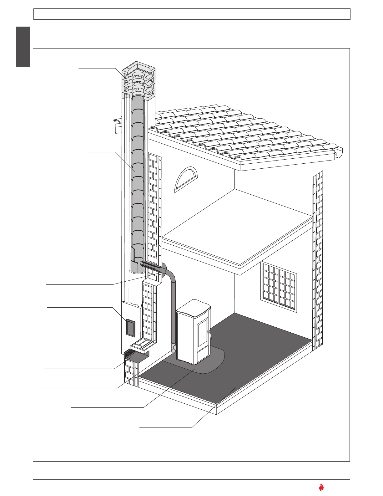
Ensure that the installation of your product conforms to all the indications given below.
Fig. 1
CHIMNEY STACK
SINGLE FLUEWAY
OR CHIMNEY
CONNECTION TO FLUE
SOOT INSPECTION
APERTURE
FRESH AIR INTAKE
MINIMUM SAFETY DISTANCES
CAPACITY LOAD
OF THE FLOOR
END ELBOW WITH
INSPECTION WINDOW
1.0 GENERAL RULES
DT2010216-04
H07022850 / DT2000426 - 00
English
5
SUPERIOR
®
NO
X
Minimo 3,5 m
MAX 45°
NO
NO
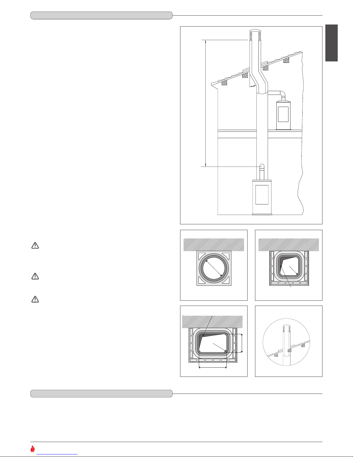
Every appliance must have a vertical flue pipe operating by natural
draught to discharge the combustion gases outdoors.
The flue must:
- comply with regulations in force in the place of installation of the
appliance;
- be tight to the products of combustion, waterproof, suitably insulated,
made with materials resistant to corrosion by the gases and to stress;
- be connected to just one stove, fireplace or extraction hood (Fig. 2);
- be properly sized, with constant free internal section, equal to or
greater than the diameter of the flue pipe of the stove and at least 3.5
m in length (Fig. 2);
- be mainly in a vertical position with a deflection from the axis of no
more than 45° (Fig. 2);
- be at a suitable distance from combustible or flammable materials,
ensured by an air gap or suitable insulating material;
- be of uniform internal section, preferably round. Square or
rectangular sections must have rounded corners with a radius of at
least 20mm and a maximum ratio between the sides of 1.5 (Fig. 3-4-
5). The walls must be smooth if possible and without narrowing.
Bends must be regular and without discontinuity (Fig. 6).
It is forbidden to make fixed or mobile apertures on the flue
pipe to connect appliances other than the one to which it is
already connected.
It is forbidden to pass other air ducts or service pipes inside
the flue pipe, however large it is.
If the flue pipe is an incorrect size or installed other than in
compliance with the above instructions, Gruppo Piazzetta
S.p.A. cannot be held liable for malfunctioning of the product,
damage to property or injury to persons or animals.
Ø
DT2030050-00
DT2030049-00
Fig. 3
P
R (min. 20)
L (≤ 1,5 x P)
Accumulo di Creosoto
DT2030189-00
Fig. 5
R (min. 20)
Accumulo di Creosoto
DT2030188-00
Fig. 4
Fig. 2
DT2030190-00
Fig. 6
3.5 M MINIMUM
Deposit of Creosote
Deposit of Creosote
1.1 SINGLE FLUEWAY OR CHIMNEY - Fig. 2 / 6
DT2010024-02
1.2 SOOT INSPECTION - Fig. 1
DT2010031-01
We recommend that the flue must have a chamber for collecting solid matter and any condensate located below the connection and which may
be easily inspected by means of an airtight door. (Fig.1)
H07022850 / DT2000426 - 00
English
6
SUPERIOR
®
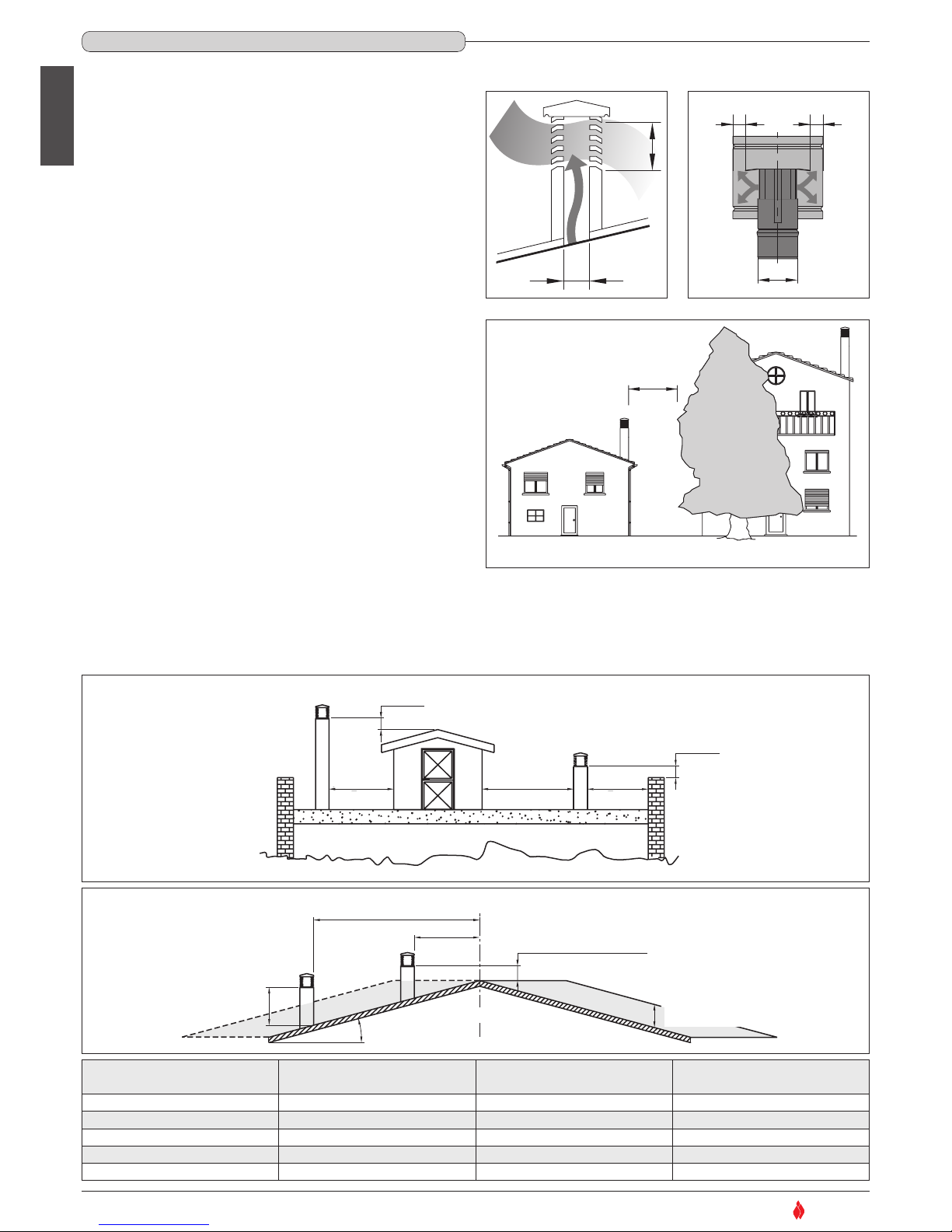
The chimney stack is a device fitted on the top of the chimney that is designed to
aid dispersion of the products of combustion in the atmosphere.
The chimney stack must comply with the following requirements:
- it must have an internal section and shape the same as the flue (A);
- it must have a useful outlet section (B) of not less than twice that of the flue (A);
- the part of the chimney that emerges from the roof or remains in contact with the
outside (e.g. in the case of a flat roof), must be covered with brick or tile elements
and in any case well insulated;
- It must be built in such a way as to prevent the penetration of rain, snow and
foreign matter into the flue and to ensure that in the event of winds from all
directions and angle, discharge of the combustion products is assured (chimney
stack with down-draught cowl).
Recommended distances for correct chimney operation.
To ensure trouble-free operation of the chimney and allow correct dilution of the
products of combustion in the air, the chimney stack must be installed at the
distances given below:
- 6 - 8 metres from any buildings or other obstacles that are higher than the
chimney stack;
- 50 centimetres higher than any obstacles located at a distance less than 5 metres;
- outside the reflux area. The size and shape of this area differ according to the angle
of inclination of the roof and it is therefore necessary to adopt the minimum
heights shown below.
Example: Check the slope of the roof (column
α
), and the anticipated distance of
the chimney stack from the axis of the ridge (column A); if the distance is greater
than “A” the height of the chimney stack may be read in (column H); if the distance
is less than “A” the chimney stack must rise above the ridge by 0.5 metres.
6-8 m
DT2030052-00
Fig. 9
TETTO PIANO
0.50 m
0.50 m
maggiore 5 m
pari o minore
5 m
pari o minore
5 m
DT2030053-00
Fig. 10
TETTO PIANO
TETTO INCLINATO
0.50 m
0.50 m
0.50 m oltre il colmo
altezza zona di
reflusso Z
asse colmo
distanza maggiore A
α
H min.
distanza
min. uguale A
maggiore 5 m
pari o minore
5 m
pari o minore
5 m
Fig. 11
A
B*
* B equivale al
doppio di A
DT2030051-00
Fig. 7
A
B
B
DT2030191-00
Fig. 8
DT2030192-00
* B it is twice
of to A
FLAT ROOF
5 m
or less
5 m
or less
over 5 m
SLOPING ROOF
distance more than A
distance
at least A
ridge axis
0.50 above the ridge
height of
reflux area Z
Pitch of the roof
Horizontal width of reflux
area from ridge axis
Minimum height of
outlet from roof
Height of reflux
area
αα
A H min Z
15° 1,85 m 1,00 m 0,50 m
30° 1,50 m 1,30 m 0,80 m
45° 1,30 m 2,00 m 1,50 m
60° 1,20 m 2,60 m 2,10 m
REFLUX AREA
1.3 CHIMNEY STACK - Fig. 7 / 11
DT2010025-03
H07022850 / DT2000426 - 00
English
7
SUPERIOR
®
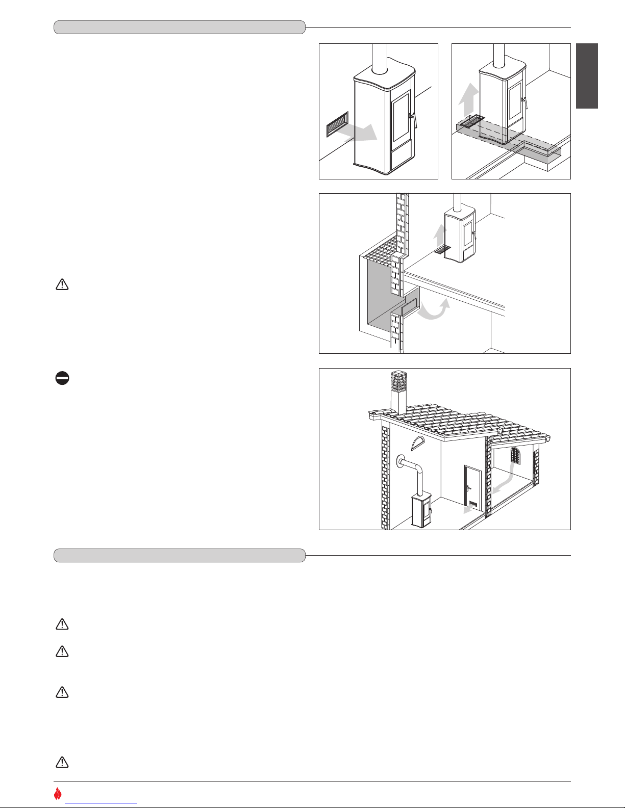
To ensure trouble-free operation the stove/fireplace must have the
necessary air available for combustion and this is provided through the
fresh air intake.
The fresh air intake must:
- have a total free cross section at least equal to the size given in the
paragraph “TECHNICAL DATA”;
- be protected by a grille or suitable guard provided it does not reduce
the minimum recommended section;
- be in a position whereby it cannot be obstructed.
The airflow necessary for the fire may be obtained in different ways:
- through a fresh air intake direct into the room of installation;
- with ducting through pipes direct to the room of installation, increasing
the recommended minimum free cross section by at least 15%;
- from an adjacent room to the place of installation provided this air flows
freely through permanent apertures communicating with the outside.
The adjacent room from which air is taken must not have a low
pressure compared to the exterior due to a counter draught
caused by the presence in that room of another appliance in
use or of a suction device.
The permanent apertures in the adjacent room must comply
with the requirements given above.
Combustion air must not be taken from adjacent rooms used
as a garage or a combustible materials store or for activities
posing a fire hazard.
DT2030054-00
Fig. 12
DT2030194-00
Fig. 14
DT2030195-00
Fig. 15
DT2030193-00
Fig. 13
1.4 FRESH AIR INTAKE - Fig. 12 / 15
DT2010539-03
1.5 INSTALLATION ENVIRONMENT
DT2010033-01
The appliance should be installed in a location which allows safe and convenient use as well as easy maintenance. If the product being installed
requires an electrical socket, the room must also be provided with an earthed power supply in accordance with current regulations.
The room where the appliance is to be installed must comply with the following requirements:
they must not be used as a garage, store for combustible material or for activities with a risk of fire.
They must not be in a vacuum in relation to the outside environment due to the effect of contrary draught caused by the presence in
the room where the fi replace is installed of another appliance or an extractor device.
Do not use two stoves, a fireplace and a stove, a stove and a wood-fired cooking range, etc. in the same environment, since the draught
of one could affect the draught of the other.
- Devices suitable for cooking food with relative hoods without an extractor fan may only be used in kitchens.
- Gas appliances of type C are allowed (refer to current legislation and regulations in the place of installation)
Gas appliances of type B are not allowed (refer to current legislation and regulations in the place of installation)
H07022850 / DT2000426 - 00
English
8
SUPERIOR
®
The stove or fireplace must not be used simultaneously with collective type ventilation ducts with or without extractor fan, other devices
or other appliances such as: forced ventilation systems or other heating systems using ventilation to change the air. Such systems could
cause a vacuum in the environment of installation even if installed in adjoining or communicating rooms.
The stove or fireplace must not be used: in stairwells except in buildings with no more than two apartments; in corridors for common
use; in bedrooms; in bathrooms or shower-rooms.
Check the load-bearing capacity of the floor, referring to the weight of the product given in the paragraph “TECHNICAL DATA”.
If the floor does not have a suitable load-bearing capacity, adequate countermeasures must be taken, for example, by using a sheet metal plate to
distribute the load.
Check the heating capacity of the appliance by comparing the rated power given in the paragraph “TECHNICAL DATA” with the power required by the
environment to be heated.
The energy requirement may be calculated approximately by multiplying the square metres of area by the height of the ceiling; the result is then
multiplied by a coefficient, which depends on the degree of insulation of the building, that is, on internal and external factors of the dwelling:
a) Internal factors: type of window and door frames, thickness of the insulation and walls, type of building materials, presence of stairwells, walls with
extensive glazing, high ceilings, position of the rooms to be heated in relation to other adjacent heated or unheated rooms, …
b) External factors: geographical position, average outdoor temperature, exposure, wind speed, latitude, altitude, …
Example of approximate calculation of the energy requirement to heat a fixed volume to 18/20° C:
The coefficient that is normally used is determined according to the real conditions as they occur case by case.
- From 0.04 to 0.05 kW per cubic metre in a well insulated environment
- From 0.05 to 0.06 kW per cubic metre in a poorly insulated environment.
3 rooms measuring 20m2 X (H ceiling) 2.7m = 162 m3 (volume)
In an environment with a good degree of insulation, an average value (coefficient) of 0.045 kW may be taken
162 (volume) X 0.045 (kW) = 7.3 kW necessary (6300 kcal/h)
Conversion 1kW = 860 kcal/h
Consult a heating technician or engineer for a correct check and calculation of the requirement of the environments to be heated (see
“REFERENCE STANDARDS”).
1.6 CAPACITY LOAD OF THE FLOOR
DT2010032-00
1.7 HEATING CAPACITY
DT2010130-01
H07022850 / DT2000426 - 00
English
9
SUPERIOR
®
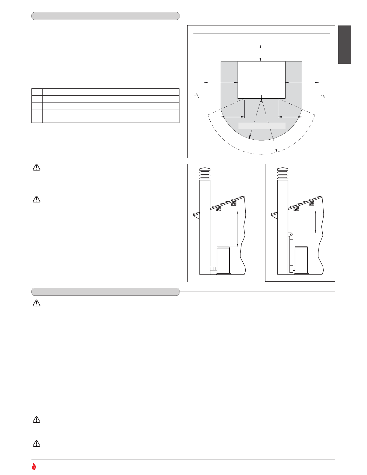
Install the product in compliance with the recommended safety
distances from heat sensitive or inflammable materials, from load
bearing and other walls and also from wooden elements, furniture, etc.
In the case of flooring that is heat sensitive or inflammable the floor must
be protected with non-combustible insulating material, e.g. sheets of
steel plate, marble, tiles, etc.
The minimum distances are:
Connection to the flue must respect the 40 cm minimum safety
distance from heat-sensitive structural components or inflammable
materials (wood panelling, beams or ceilings, etc).
Keep any combustible product such as wooden furniture,
curtains, carpets, combustible liquids, etc. well away from
the stove when it is lit (minimum distance 80 cm).
It is advisable to leave more than the recommended 20 cm
gap at the side of the stove to facilitate any maintenance on
the appliance.
The pellet stove is not the same as other stoves. It has a forced
draught of flue gas by a fan, which keeps the firebox in a vacuum
and the entire flueway slightly pressurised. For this reason the
flue must be completely airtight and correctly installed to ensure
both trouble-free operation and user safety.
- The flueway must be made by specialised personnel or firms, as outlined
below.
- The flue must be installed in such a way as to guarantee that periodic
cleaning can be carried out without dismantling any parts whatsoever.
- Pipes should always be sealed with silicone (not cement-based sealants)
or specially adapted gaskets/seals, which retain their strength and
elasticity at high temperatures (250°C), and should be fixed with 3.9 mm
ø self-tapping screws.
Do not install dampers or valves that could block the passage of
flue gas.
Do not connect to a flueway into which other appliances (boilers,
extractor hoods, etc.) discharge fumes or vapours.
MIN 40 cm
DT2030335-00
Fig. 17
MIN 40 cm
DT2030336-00
Fig. 18
Protezione pavimento
Zona radiante dell’apertura
del focolare
Parete posteriore
Parete laterale
Parete laterale
B B
A
D
C
STUFA
E E
DT2031515-00
Fig. 16
Rear wall
Side wall
Side wall
STOVE
Heat radiation area
Floor protection
A 20 cm from the wall behind the stove
B 20 cm from the side wall
C 80cm in the heat radiation area and from the hot air fan outlet
D 50 cm floor protection
E 30 cm (measured from the internal corner of the door opening)
1.8 MINIMUM SAFETY DISTANCES - Fig. 16 / 18
DT2010536-02
1.9 FLUEWAY - Fig. 19 - 20
DT2010229-04
H07022850 / DT2000426 - 00
Pipes and maximum usable lengths
Pipes of painted aluminium-clad steel (minimum thickness
1.5mm), stainless steel (AISI 316) or enamelled steel (minimum
thickness 0.5mm) with a nominal diameter of 80 or 100 mm (for
pipes which run inside the flue maximum diameter 150 mm) can be
used.
The male-female connectors must have a minimum length of 50
mm.
The diameter of the pipes depends on the type of installation. The
stove was designed to take 80 mm diameter pipes but, as shown
in Table 1, in some cases the use of double-lined 100 mm diameter
pipes is recommended.
Losses in pressure associated with a 90° bend can be
compared to those incurred by one metre of pipe. An
inspectable union-tee can be considered equivalent to a 90°
bend.
EXAMPLE: : if installing a section greater than 4.5m in length with
80mm diameter pipe, calculate the maximum usable length in the
following ways:
- If a maximum of three 90° bends are used, the maximum length of
the section will be 4.5m
- If a maximum of two 90° bends are used and bearing in mind that a
90° bend can be replaced by one metre of pipe, the maximum length
of the section will be 4.5m+1m=5.5m
- If a maximum of one 90° bend is used and bearing in mind that a 90°
bend can be replaced by one metre of pipe, the maximum length of
the section will be 4.5m+1m+1m=6.5m
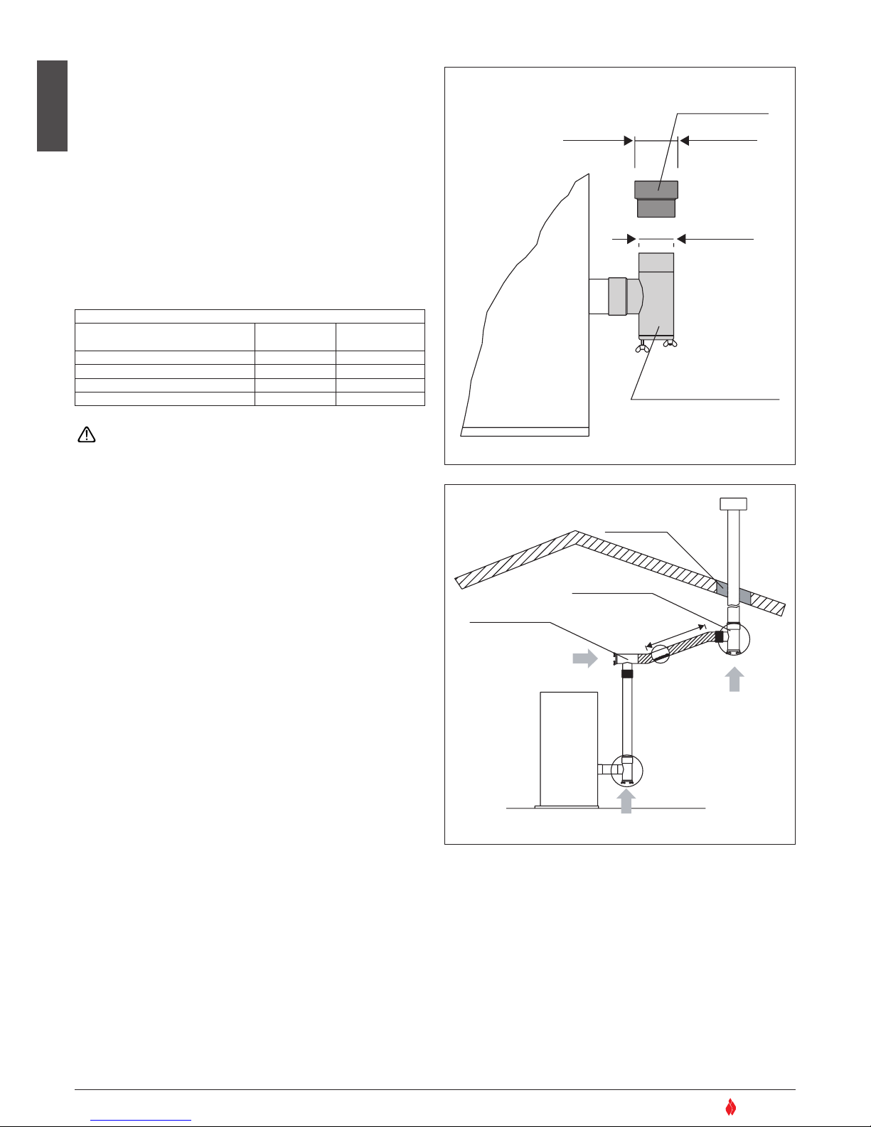
Where 100mm diameter pipe must be used, connect it to the stove
flue outlet with a 80mm union-tee then use a 80mm 100mm adaptor
(not supplied by Superior) (Fig. 19).
Union-tee
The use of this type of fitting must allow for the collection of
condensate mixed with soot, which builds up inside the pipe. It must
also permit periodic cleaning of the flue without the need to
disassemble the pipes.
This type of fitting can be bought at Superior retail outlets together
with the pipes.
An example is given below of a flueway connection, which allows
complete cleaning without having to disassemble the pipes (Fig 20).
English
10
SUPERIOR
®
TABLE 1 – LENGHT PIPES
TYPE OF INSTALLATION
WITH 80mm Ø PIPE
WITH DOUBLE-WALLED
100mm Ø PIPE
Maximum length (with three 90° bends) 4.5 m 8 m
For installations more than 1200m above sea level
- Required
Maximum number of bends 3 4
Length of horizontal sections with minimum 3% gradient
2 m 2 m
RACCORDO A T CON TAPPO
A CHIUSURA ERMETICA
RACCORDO
ø 80 > ø 100
ø 80mm
ø 100mm
DT2030337-00
Fig. 19
ISOLANTE
RACCORDO A T
RACCORDO A T
DIREZIONE
DI PULIZIA
DIREZIONE DI PULIZIA
Max 2m
(min. 3%)
DIREZIONE DI PULIZIA
DT2030338-00
Fig. 20
Straight reducer
ø 80 > ø 100
Tee with sealing plug
Insulating material
Tee
Tee
Direction of
cleaning
Direction of cleaning
Direction of cleaning
H07022850 / DT2000426 - 00
English
11
SUPERIOR
®
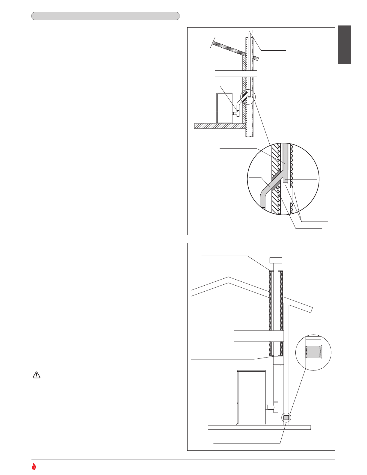
If you wish to use an existing chimney it is strongly recommended that
you have it checked by a professional chimneysweep to ensure that it
is completely airtight. The reason for this is that the smoke, because it
is slightly pressurised, can infiltrate any cracks in the flue and escape
into living spaces. If upon inspection you find that the chimney is not
completely sound, it is recommended that you insert piping made of
new material. If the existing chimney is wide enough we recommend a
pipe with a maximum diameter of 150mm. It is also recommended that
you insulate the chimney flue (Fig. 21-22).
Pipes and bends made by Gruppo Piazzetta S.p.A. are recommended
for connection to the flueway, since they are sized to fit the flue outlet
of the appliance.
Other pipes may be applied after adaptation and checking of the
compatibility of the coupling, taking into account that the pipes and
bends must be made in compliance with current regulations. In this
case, however, Gruppo Piazzetta S.p.A. only guarantees trouble-free
operation for parts that it manufactures and that are used according to
specifications.
Connection to the flue must respect the 40cm minimum safety
distance from heat-sensitive structural components or inflammable
materials (wood panelling, beams or ceilings, etc). (See figures 17-18).
- If the connector has to pass through partitions or walls of inflammable
or heat-sensitive materials, or through load-bearing walls, create:
an insulating barrier equal to or greater than 10cm around the
connector using mineral-based insulating material (rock wool,
ceramic fibre) with a nominal density greater than 80kg/m3.
- If the connector has to pass through non-flammable partitions or
walls, create:
an insulating barrier equal to or greater than 5cm around the
connector using mineral-based insulating material (rock wool,
ceramic fibre) with a nominal density greater than 80kg/m3.
- Check that the connection to the flueway is gas/smoke-tight, since
the appliance operates in a vacuum.
- Check that the pipe does not penetrate too far into the flueway,
thereby choking the pipe for the passage of smoke and combustion
gases.
Ensure that all installation work is carried out to professional
standards.
COMIGNOLO
RACCORDO A T
CON CANNA FUMARIA
NON INTEGRA
INSERIMENTO DI
UN TUBO
SPORTELLI PER
ISPEZIONE
ISOLANTE
Max ø150 mm
ø 80 mm
DT2030339-01
Fig. 21
FLANGIA DI CHIUSURA
FLANGIA DI CHIUSURA ERMETICA
IN ACCIAIO INOX O ALLUMINATO
PRESA D'ARIA ESTERNA
CON GRIGLIA NON RICHIUDIBILE
DT2030340-00
Fig. 22
Insulating material
Tee
Chimney stack
Pipe insertion
With damaged flue
Inspection
windows
Closing flange
Sealing flange in stainless
steel or aluminium
Fresh air intake with
non-closable grille
1.10 CONNECTING TO A CONVENTIONAL CHIMNEY - Fig.21 - 22
DT2010230-02
H07022850 / DT2000426 - 00
English
12
SUPERIOR
®
PRESA D'ARIA ESTERNA CON
GRIGLIA NON RICHIUDIBILE
d
DT2030341-00
Fig. 23
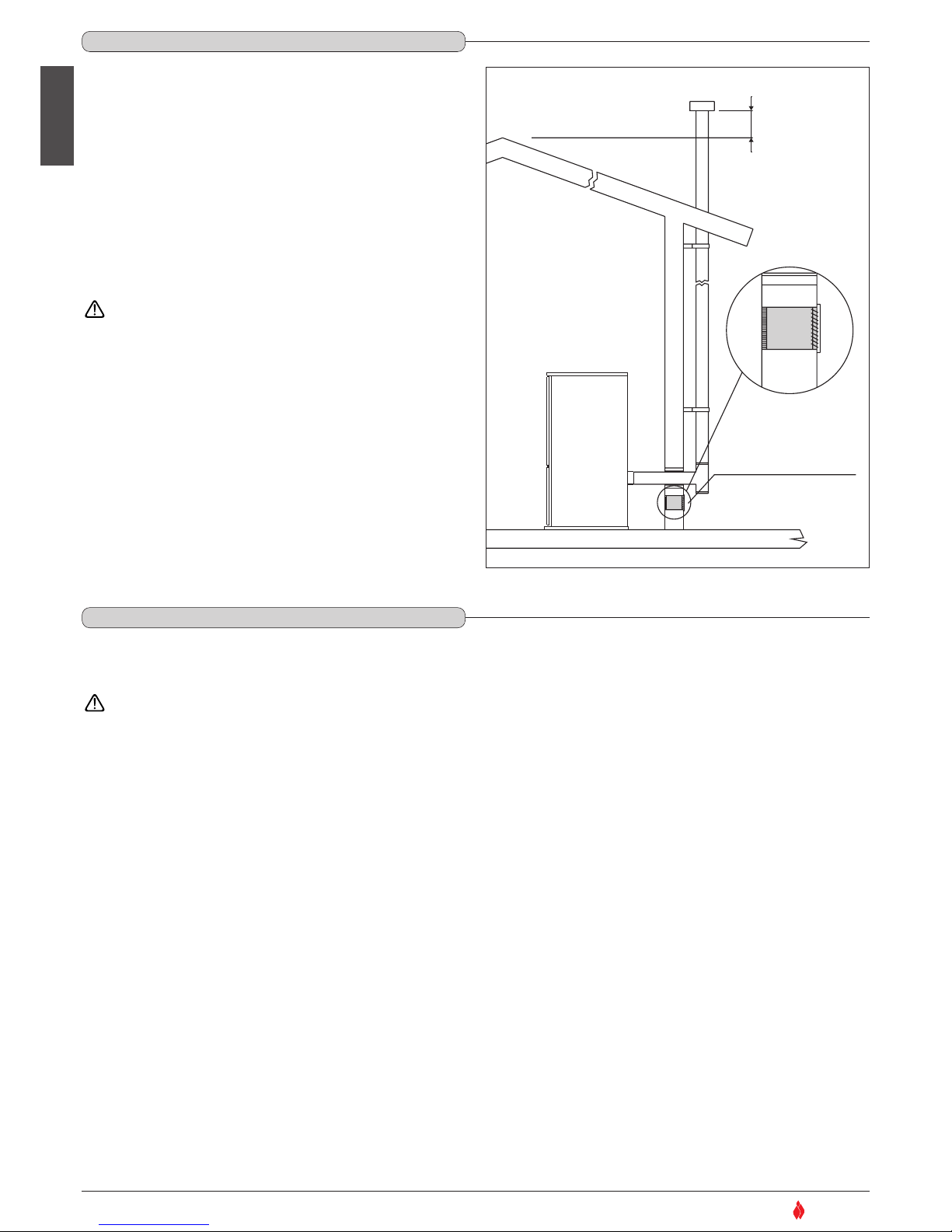
An external flue can be used provided it complies with the following
requirements:
- use only insulated stainless steel pipes (double-lined) fixed to the
outside wall of the building (Fig. 23);
- there must be an inspection opening at the base of the flue to permit
periodic checks and maintenance;
- the flue must be fitted at the top with a chimney stack with downdraught cowl, also ensuring compliance with the safety distance from
the roof ridge as outlined in the section entitled “GENERAL RULES”,
under “CHIMNEY STACK”.
Ensure that all installation work is carried out to professional
standards.
Fresh air intake with
non-closable grille
1.11 USING AN EXTERNAL FLUE - Fig. 23
DT2010232-02
1.12 PREVENTION OF DOMESTIC FIRES
DT2010027-02
The product must be installed and used in compliance with the manufacturer’s instructions and European and national standards as well as local
regulations.
When a flue pipe passes through a wall or a ceiling, special installation methods must be applied (protection, thermal insulation,
distances from heat-sensitive materials, etc.) See the paragraph “FLUEWAY”
- It is also recommended that all elements made of combustible or inflammable material, such as beams, wooden furniture, curtaining, flammable
liquids, etc. be kept outside the heat radiation range of the stove and in any case at a distance of at least 80 cm from the heating block.
- For other information, see the paragraph “MINIMUM SAFETY DISTANCES” and “CONNECTION TO A CONVENTIONAL CHIMNEY”.
- The flue pipe, chimney stack, chimney and fresh air intake must always be free of obstructions, clean and checked periodically, that is, at least
twice during the seasonal period from the lighting of the stove and during its use. When the stove has not been used for some time it is advisable
to carry out the checks mentioned above. For further information, consult a chimneysweep.
- Only use recommended fuels (See section “FUEL”).
H07022850 / DT2000426 - 00
 Loading...