

Superior SLO-SYN SS2000MD7, SLO-SYN SS2000MD7-128 Installation Instructions Manual

INSTALLATION
INSTRUCTIONS
for
SLO-SYN
®
MODELS SS2000MD7 &
SS2000MD7-128
TRANSLATOR/DRIVE

2
TABLE OF CONTENTS
Page
THINGS TO KNOW BEFORE USING THIS
EQUIPMENT ........................................................................... 3
WARRANTY RESTRICTIONS...................................................... 3
SECTION 1: INTRODUCTION ..................................................... 3
1.1 Using This Manual............................................. 3
1.2 Product Features ............................................... 4
SECTION 2: EXPRESS START UP
PROCEDURE.................................................................. 5
SECTION 3: INSTALLATION GUIDELINES................................ 6
3.1 Mounting............................................................ 6
3.2 Connector Locations And Pin
Assignments ...................................................... 7
SECTION 4: SPECIFICATIONS................................................... 11
4.1 Mechanical Specifications ................................. 11
4.2 Electrical Specifications..................................... 11
4.3 Environmental Specifications............................. 12
4.4 Motor Compatibility............................................ 12
4.5 Current Settings................................................. 14
4.6 Step Resolution.................................................. 14
4.7 Signal Specifications.......................................... 15
4.8 Indicator Lights................................................... 18
SECTION 5: TORQUE VERSUS SPEED
CHARACTERISTICS ...................................................... 18
5.1 Motor Performance............................................ 18
5.2 Typical Torque Vs. Speed Curves..................... 19
SECTION 6: TROUBLESHOOTING............................................. 29
APPENDIX A: TROUBLESHOOTING ELECTRICAL
INTERFERENCE PROBLEMS ....................................... 31

3
THINGS TO KNOW BEFORE USING THIS
EQUIPMENT
• Only qualified personnel should install or perform servicing
procedures on this equipment. Do not operate the unit without the
enclosures in place as voltage present in this unit can cause
serious or fatal injury.
• Before performing any work on the unit, allow at least five minutes
for the capacitors to discharge fully.
• Voltage is present on unprotected pins when unit is operational.
• The "PWR ON" LED must be off for approximately 30 seconds
before making or breaking the motor connections.
• Motors powered by this drive may develop extremely high torque.
Be sure to disconnect power to this drive before doing any
mechanical work.
CAUTION:
This unit is designed for 24 to 75 Vdc input only (see Section
4.2, Electrical Specifications, Page 11).
WARRANTY RESTRICTIONS
Reconfiguration of the circuit in any fashion not shown in this manual will
void the Warranty.
Failure to follow the installation guidelines as described in Section 3 will
void the Warranty.
SECTION 1: INTRODUCTION
1.1 USING THIS MANUAL
It is important that you understand how this SLO-SYN SS2000MD7
Translator/Drive is installed and operated before you attempt to use it.
We strongly recommend that you read this manual completely
before proceeding with the installation of this unit.

4
This manual is an installation and operating guide to the SLO-SYN
SS2000MD7 Translator/Drive. Section 1 gives an overview of the Drive
and its features. Section 2 describes the steps necessary to place the
drive into operation. General wiring guidelines as well as the physical
mounting of the unit and connections to the drive portion are covered in
Section 3.
Complete specifications, listed in Section 4, provide easily referenced
information concerning electrical, mechanical and environmental
specifications. The procedure for setting the motor current level is also
covered in this section.
Torque versus speed characteristics with all appropriate SLO-SYN
Stepper Motors are given in Section 5. Section 6, Troubleshooting, gives
procedures to follow if the Translator/Drive fails to operate properly.
Appendix A provides procedures for troubleshooting electrical interference problems.
1.2 PRODUCT FEATURES
The SLO-SYN SS2000MD7(MD7-128) Translator/Drive is a bipolar,
speed adjustable, two-phase PWM drive which uses power MOSFET
devices. The MD7 can be set to operate a stepper motor in 1/2, 1/10,
1/25 or 1/100 microsteps. The MD7-128 can be set to operate a
stepper motor in Full, 1/16, 1/64, or 1/128 microsteps. The maximum
running speed is 3,000 rpm. To reduce the chances of electrical noise
problems, the control signals are optically isolated from the drive
circuit.
• UL recognized under Component Program, File #E146240
• Switch selectable current levels of 1 through 7 amperes
• Full short circuit protection (phase-to-phase and phase-to-ground)
• Undervoltage and transient overvoltage protection
• Thermal protection
• Efficient thermal design
• Optically isolated inputs
• Reduce Current and Windings Off capabilities
• Switch selectable step resolution
• Compact size
• Sturdy all-aluminum case

5
SECTION 2: EXPRESS START UP PROCEDURE
The following instructions define the minimum steps necessary to
make your Drive operational.
CAUTION:
Always disconnect the power to the unit and be certain that the
"PWR ON" LED is OFF before connecting or disconnecting the
motor leads. FAILURE TO DO THIS WILL RESULT IN A SHOCK
HAZARD AND MAY DAMAGE THE DRIVE.
Always operate the unit with the Motor and the Drive enclosure
GROUNDED. Be sure to twist together the wires for each motor
phase as well as those for the dc input. Six twists per foot is a
good guideline.
1. Check to see that the motor used is compatible with the drive.
Refer to Section 4.4 for a list of compatible motors.
2. Set the correct current level for the motor being used per the
instructions in Section 4.5. Heat sinking is required if a current
of 4 amperes or higher is used.
3. Select the appropriate step resolution and set the switches as
described in Section 4.6.
4. Wire the motor per the "Motor Connections" description in Section 3.2.
5. Connect the power source to the DC input terminal strip. Be sure
to follow the instructions for connecting the filter capacitor as
described in Section 3.2, under Power Input.
NOTES:
If the motor operates erratically, refer to Section 5, "Torque Versus
Speed Characteristics".
Clockwise and counterclockwise directions are properly oriented
when viewing the motor from the end opposite the mounting flange.
6
SECTION 3: INSTALLATION GUIDELINES
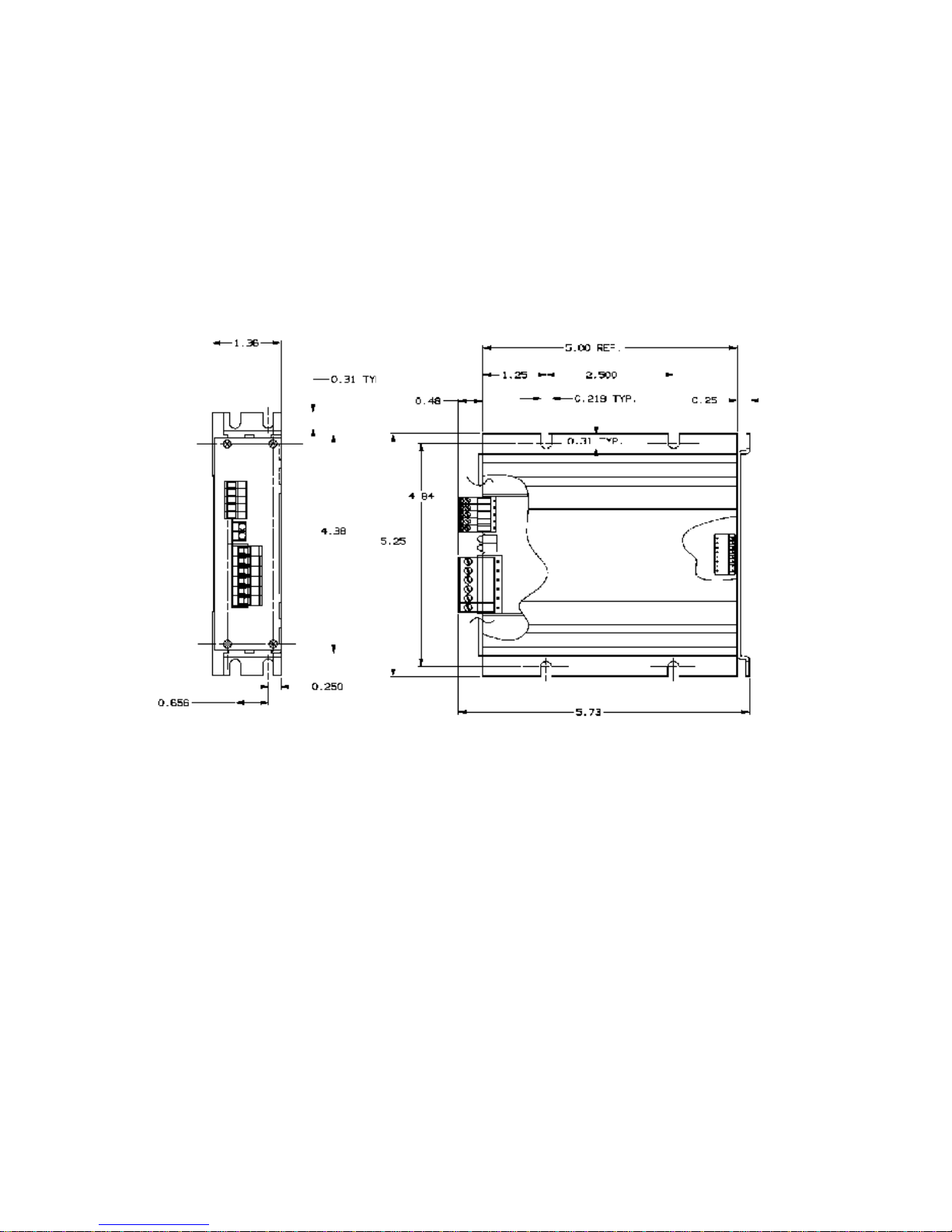
3.1 MOUNTING
The SLO-SYN Drive is mounted by fastening its mounting brackets to a
flat surface as shown in Figure 3.1. If the Heat Sink Assembly, part
number 221576-001, is mounted against a bulkhead, be sure to apply a
thin coating of thermal compound between the heat sink and the
mounting surface before fastening the unit in place. Do not use too much
thermal compound. It is better to use too little than too much.
Figure 3.1, Mounting Diagram
NOTE: Case temperature should not exceed +70º C (+158º F). A
heat sink, such as Superior Electric Heat Sink Assembly
221576-001, must be used when the drive is operated at a
current setting of 4 amperes or more. In this case the unit
should be mounted upright (with the cooling fins vertical)
, or proper cooling will not occur. Air flow should not be
obstructed. Forced air cooling may be required to maintain
temperature within the stated limits.
When selecting a mounting location, it is important to leave at least two
inches (51mm) of space around the top, bottom and sides of the unit to
allow proper airflow for cooling.

7
It is also important to keep the drive away from obvious noise sources.
If possible, locate the drive in its own metal enclosure to shield it and its
wiring from electrical noise sources. If this cannot be done, keep the
drive at least three feet from any noise sources.
3.2CONNECTOR LOCATIONS AND PIN ASSIGN-
MENTS
Figure 3.2 shows the connector locations for the SLO-SYN SS2000MD7
Translator/Drive.
Figure 3.2, Connector Locations
MOTOR CONNECTIONS

8
All motor connections are made via the 6-pin connector, part number
218397-006. Pin assignments for this connector are given below. Motor
connections are shown in Figure 3.3.
Pin Assignment
1 M1 (Phase A)
2 M3 (Phase A)
3 M4 (Phase B)
4 M5 (Phase B)
NOTE: Motor phase A is M1 and M3 and motor phase B is M4 and
M5. The motor frame must be grounded.
Cabling from the drive to the motor should be done with a shielded,
twisted-pair cable. As a guideline, the wires for each motor phase should
be twisted about six times per foot.
Superior Electric offers the following motor cable configurations. These
cables have unterminated leads on both ends.
Length Part Number
10 ft (3 m) 216022-031
25 ft (7.6 m) 216022-032
50 ft (15.2 m) 216022-033
75 ft (22.8 m) 216022-034
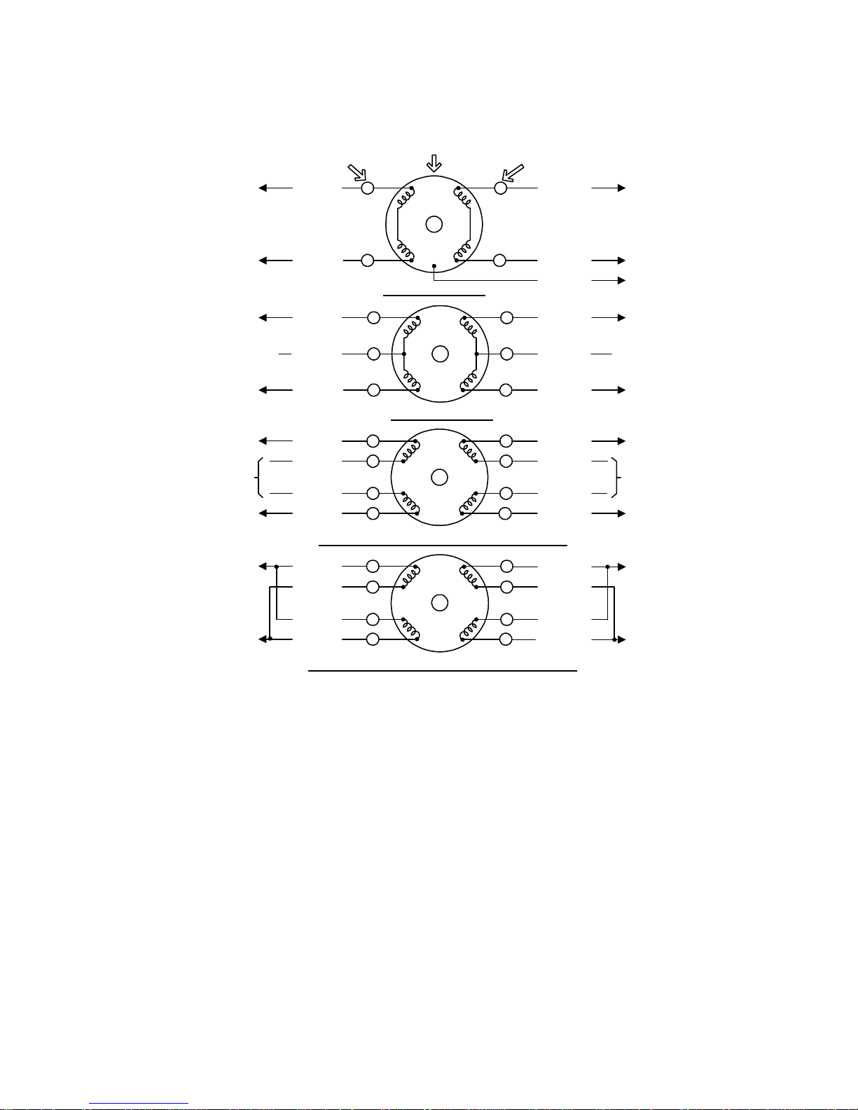
Figure 3.3 shows the possible motor wiring configurations.
9
* These leads must be insulated and isolated from other leads
or ground.
Circled letters identify terminals for connector motors, numbers identify
those for terminal box motors.
Figure 3.3, Motor Wiring Configurations
D
F
B
H
5
4
1
3
WHITE/
BLACK
BLACK
WHITE/
RED
RED
GREEN
MOTOR TERMINAL "M" NUMBERS
MOTOR
CONNECTOR PIN
MOTOR
CONNECTOR PIN
4-LEAD MOTORS
D
F
B
H
5
4
1
3
GREEN
WHITE/
RED
RED
6-LEAD MOTORS
WHITE
N.C.*E
2
G
* N.C.
BLACK
WHITE/
GREEN
D
F
B
H
5
4
1
3
WHITE/
BLACK
WHITE/
RED
RED
8-LEAD MOTORS, SERIES CONNECTIONS
G
BLACK
A
WHITE
ORANGE
E
GREEN
C
WHITE/
GREEN
*
6
2
7
8
*
DRIVE PIN 1
DRIVE PIN 2
DRIVE PIN 1
DRIVE PIN 2
DRIVE PIN 1
DRIVE PIN 2
DRIVE PIN 4
DRIVE PIN 3
DRIVE PIN 4
DRIVE PIN 3
DRIVE PIN 4
DRIVE PIN 3
D
F
B
H
5
4
1
3
WHITE/
RED
RED
8-LEAD MOTORS, PARALLEL CONNECTIONS
WHITE/
BLACK
GBLACK
AWHITE
ORANGEE
C
6
2
7
8
GREEN
WHITE/
GREEN
DRIVE PIN 4
DRIVE PIN 3
DRIVE PIN 1
DRIVE PIN 2
6
10
POWER INPUT
The dc input power is connected to pins 5 and 6 of the power connector.
Pin 5 [Vm(+)] is the power supply plus (+) connection and pin 6 [Vom(-)]
is the power supply minus (-) connection.
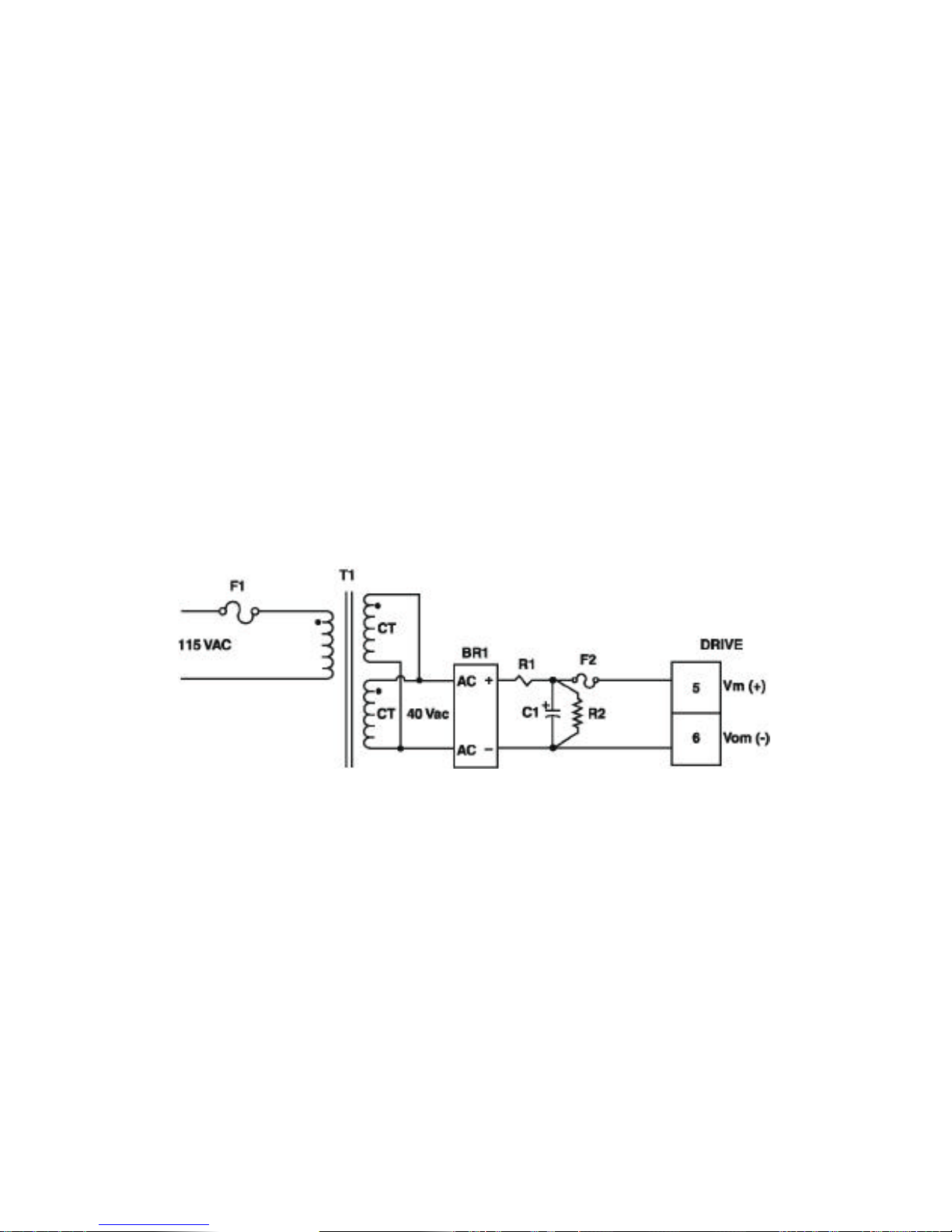
An unregulated supply similar to that shown in Figure 3.4 is
preferable. If a regulated supply is used, it must be a linear
regulated supply and must be capable of operating with the added
filter capacitor. A switching regulated supply is not recommended
for use with this drive. It is important that capacitor (C1) be
connected within three feet (0.9 meter) of the input terminals. The
capacitor must be of the correct value and have the proper current
and voltage parameters (see list of components on page 11).
It is recommended that the power supply leads be twisted together (6
twists per foot).
NOTE: If the power supply is grounded, it must only be grounded
on the negative side or the short circuit protection will not
operate properly.
NOTES: The cable between the filter capacitor (C1) and the drive
should be twisted (six twists per foot). Maximum wire
length is three feet.
Use #16 AWG or larger wire.
Figure 3.4
Typical Power Supply For A Single Drive Application
 Loading...