

Page 1
The Fireplace Compcny
For
Superior
j
HC
Series Fireplaces
1
Model
HC-3320
Model
HC-3820
And
Hearthstar
B
Series
Fireplace
Model
385
This installation manual will
help you obtain a safe, effi-
'cient, dependable installation
for your fireplace and chimney
sysiem. Please read and
understand these installation
instructions before beginning
your installation.
Do not attempt to modify or
alter the construction of the
fireplace or its components.
Any modification or aitaration
of construction may void the
'warranty, listings and appro-
vals of this system.
The name Superior
is
used
synonymously with the name
Hearthstar throughout this
Installation Instruction
manual.
Page 2
L
I
RULES
TO FOLLOW
1
10.
Alwavs keeo flue damner I
'
PRECAIITlnNS
I
~.
. . .
-
-
. .
-
.
.
-
.
.
-
FOR
SAFETY
open whiie heat is present in
fireplace.
The most imoortant
ar~zr
nf
1.
Before starting your fireplace installation, read and
understand these safety tips
and installation instructions
:~carefully. Failure to follow
them couid cause a fireplace
malfunction resulting in serious bodily injury
and/or pro-
perty damage.
2.
Always check your local
building codes. The installation must comply
with their
regulations.
3.
Connect this model fire-
place to a Superior Model
TF8
.Thru Flow Chimney System
'(8"
inside diameter) residen.
tial type appliance chimney
only and vent to the outside
!of the building.
1
4.
To maintain top effi-
iciency, and to prevent build.
up
of soot and creosote,
inspect and clean the fireplace and chimney prior to
use and periodically during
,the heatina season.
'11.
Before servicing, allow
fireplace to cool. Always shut
off any electricity and gas (if
used) to fireplace whiie work-
ing on it. This will prevent
electrical shocks or burns.
12.
This fireplace is not
intended to heat an entire
home. Its use
shou!d be for
supplemental
heat in^
only.
13.
Ensure an adequate
supply of cornbustion air to
prevent hazards due to poor
combustion and to avoid
affecting other
fuel burning
appliances.
TOOLS
AND
BUILDING
SUPPLIES NORMALLY
REQUIREO
Tools should include:
Phillips screwdriver
Slot styie screwdriver
Hammer
Saw
andior Sabersaw
6.
Do NOT use
gas
is
used:
This fuel gives
bon monoxide fumes. Pipe cutter
-
!
5.
Use solid wood fuel only.
DO NOT use artificial logs,
'chemical chimney cleaners,
:coal or flame colorants in
your fireplace.
7.
NEVER light a fire with
gasoline, kerosene or lighter
fluid because of the danaer of
1
Level
,
~~~~~~i~~
tape
:
Plumb line
!
Electric drill and bits
I
Pliers
Square
Pipe threader
Pipe joint compound
Pipe key valve
explosion. Keep all
volatTle
I
'Building supplies:
liquids away from fireplace.
Framinq materials
8.
DO
NOT INSTALL FIRE.
Wall
f16shing materials
PLACE IN A BEDROOM OF
A
Caulking materials
MANUFACTURED HOME.
(noncombust~ble)
-~
9.
NEVER leave children
:unattended when there is a
.fire burning in the fireplace
Fireplace surround and
hearth extension materials
(noncombustibie)
F~
-,
concern dealing with the
installation of Zero clearance
fireplaces are clearances to
combustible materials, secure
assembiy of component parts,
height of chimney system, the
proper use of accessory
equipment, and the techniques employed in using finishing materials applied to
fireplace surrounds, hearth
extensions and wall shields.
Each of these topics will be
covered in great detail
throughout this manual.
Please give each your special
attention as you progress with
your installation.
Page 3
INTRODUCTION
General Information
The HC and B units are
energy-efficient, heatcirculating fireplaces,
fea.
turing a self-contained heat
circulating system, full refrzctory lined firebox, optional
outside combustion air kit,
optional glass doors and
optional forced air fan kit (outside combustion air and glass
doors are required for manufactured housing).
Your
HC
(or
8)
fireplace has
,been tested and listed to be
,
installed in both conventional
and manufactured homes by
Underwriters Laboratories,
Inc. (NO.
MH-8988);
other
agency listings are pending.
You will receive a lifetime of
comfort and enjoyment from
your fireplace provided it is
installed, maintained and
1
operated properly. These
instructions are written to
give you an easy-to-follow
out.
line for fast, safe installation
and trouble-free operation.
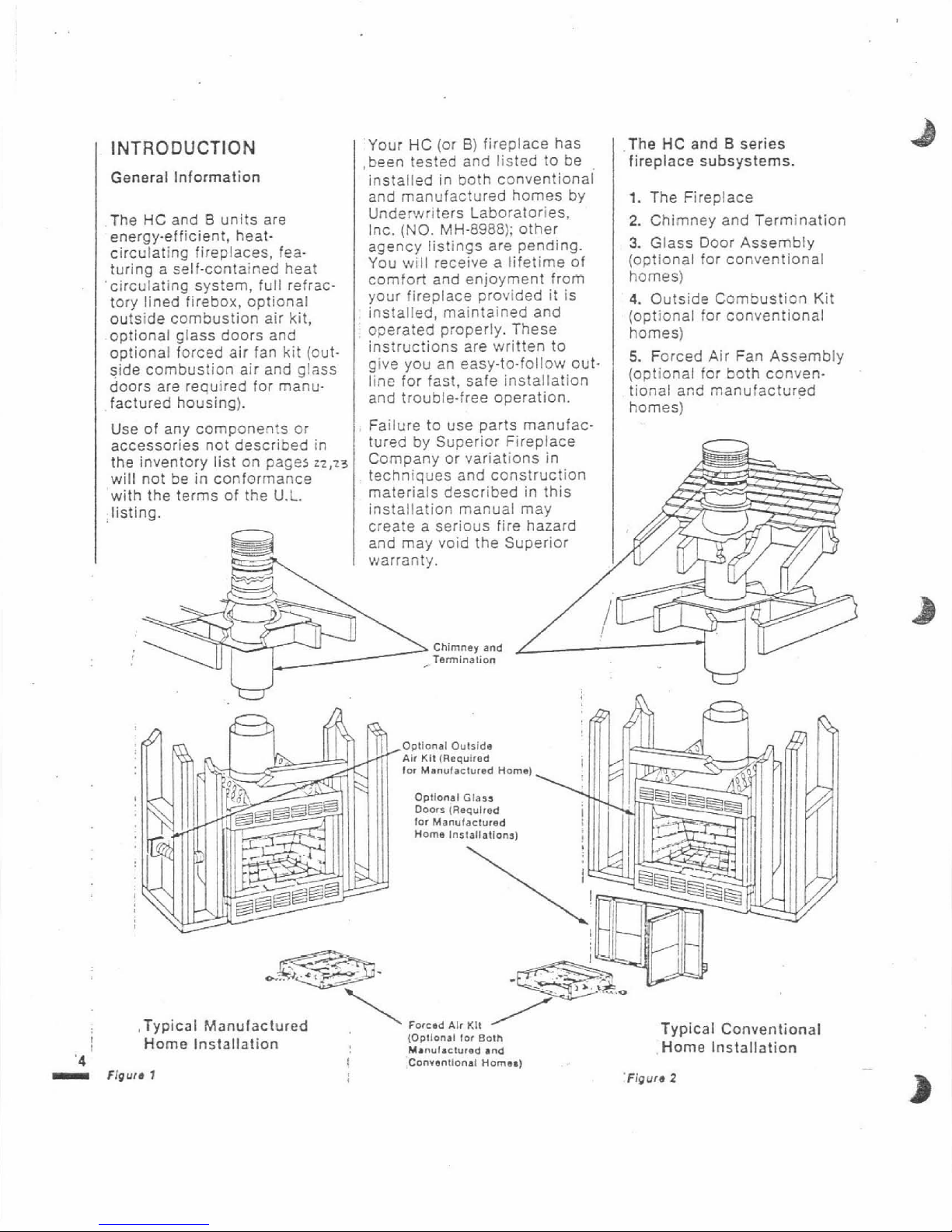
The
HC and B series
fireplace subsystems.
1.
The Fireplace
2.
Chimney and Termination
3.
Glass Door Assembly
(optional for conventional
homes)
4.
Outside Combusticn Kit
(optional for
conventional
homes)
5.
Forced Air Fan Assembly
(optional for both conventional and manufactured
homes)
Optional
Outside
Air
Kit
(Required
for
Manufactured
Home)
Opltonai
Glass
Doors
(Required
lor
Manulactured
Home
Installatton.)
!
\
.Typical Manufactured
Forcad
AIC
KII
(Optionat
lor
BOI~
Typical Conventional
Home Installation
~.~~~~~t~~~d
and
Home Installation
I
Conrsnllonal
Homal)
Figure
1
'Figure
2
Use of any components or
I Failure to use parts rnanufac-
accessories not described in
the inventory list on pages
~2,~~
will not be in conformance
with the terms of the
U.L.
listing.
tured by Superior Fireplace
Company or variations in
techniques and construction
materials described in this
installation manual may
create a serious fire hazard
and may void the Superior
warranty.
Chimney
and
Termination
Page 4
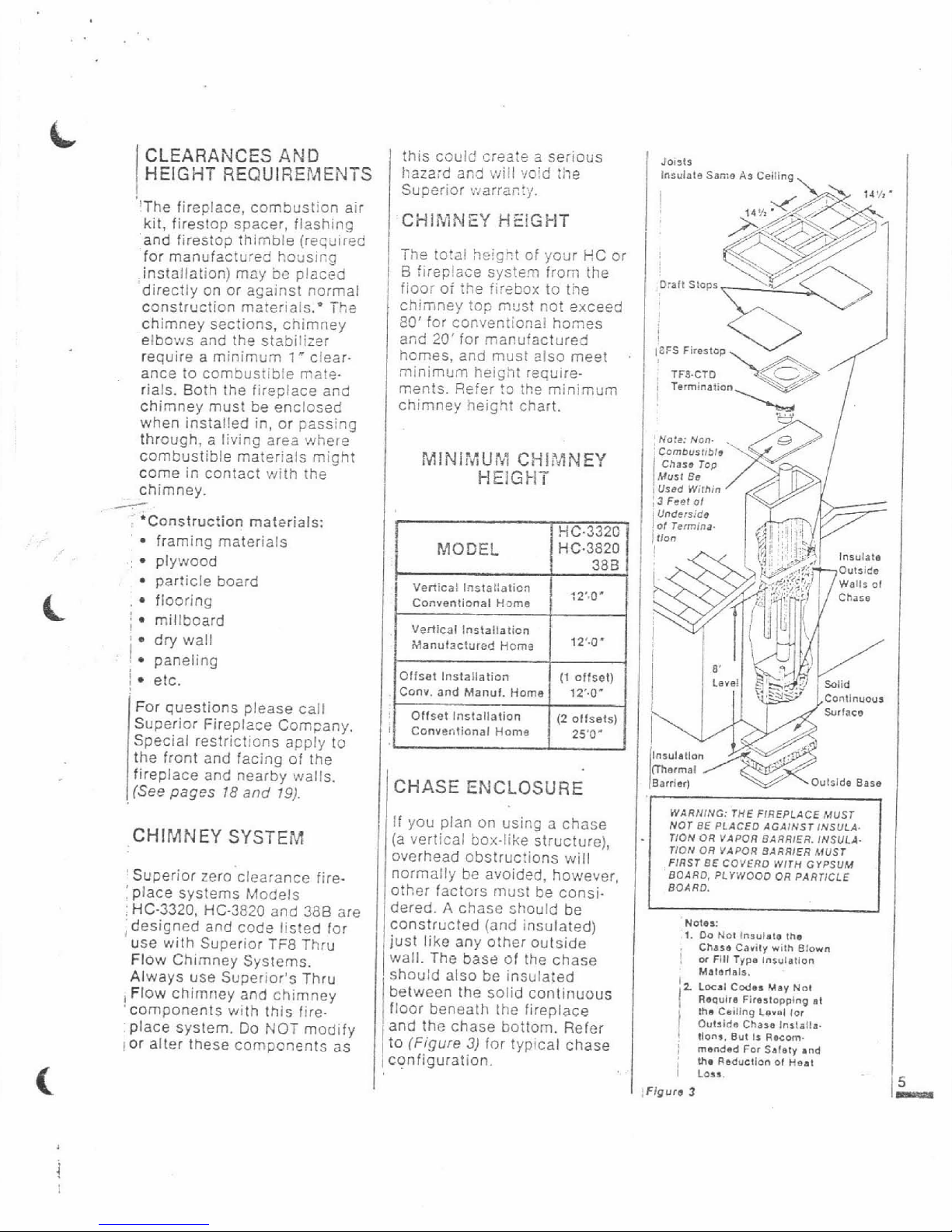
CLEARANCES
AND
this could srea!e a serious
loilto
HEIGHT REQUIEEFJENTS
hazard
an3 will void the
lnsuiats
ssma
~3
Ceiling
!
Superior .v~arra;l:y.
I4
"Z
-
'The fireplace, combustion air
CHIMNEY
HSIGHT
kit, firestop spacer, flashing
'and
firestop thimble (required
for manufactured
houslcg
I
The total hei5r.t of yogr HC or
;
installation) may
be
pIac?d
1
6
fireplace system irom the
directly on or against normal
1
fioor of
:he
firebox to the
construction materials.' The
1
chmney !a? must not exceed
chimney sections, chimney
e0'
for conventional homes
elbows and the
s:abiiizer
and
20'
for manufactured
i
homes, and must also meet
require a minimum
1
*
clear.
ance to combusrlble mate
minimum
kei~ht require-
rials. Eoth the fireplace and
men:s. Pefer !o the minimum
chimney must be enclosed
chimney height chart.
when installed in, or passing
through, a living area 'where
combustible materials might
1
MINi?liU&
CHIMNEY
come in contact with the
HEIGHT
chimney.
.
;
'Construction materials:
framing materials
:
plywood
particle board
Vertical
Installation
,
flooring Conventional
H'>rna
j
millboard
Vertical
Installation
:
dry wall
Manufactured
Homa
12''0*
'
paneling
i
I
etc.
Offset
Installatioil
(1
offset)
Conv.
and
Manuf.
Home
12'4'
!
For questions please call
Surlacs
Superior Fireplace Com;any.
,
,,,,,,
ianal
I
5.0.
Special restrictions apply
to
the front and facing of the
fireplace
and nearby walls.
I
CHASE ENCLOSURE
Barrier)
Outride
Base
(See pages
18
and
19).
WARNING:
THE
FIREPLaCE
MUST
If you plan on using a chase
NOT
BE
PLACED
AGAINST
INSULA.
,CHIMNEY
SYSTEM
(a vertical box.like structure),
"ON
OR
VAPOR
BARRIER.
1NSuI.A.
overhead obstructions will
TION
OR
VAPOR
YARRIER
MUST
FIRST
BE
COVER0
WITH
GYPSUM
I
Superior zero clearance fire-
normally be avoided, however,
BOARD.
PLIWOOO OR
PARTICLE
:place systems Models
other factors must be
consi.
BO4RO.
:
HC-3320, HC-3820
and
386
are
&red. A chase should be
;designed and cod- listed
for
use with Superior TFB Thru
Flow Chimney Systems.
Always use Superior's Thru
i
Flow chimney and chimney
'components with this fire.
place system. Do
NOT
modify
lor alter these components as
sl
constructed (and insulated)
,just like any other Outside
Wall. The base of the chase
should also
be insulated
between the solid continuous
floor beneath the
fireplace
'and the chase bottom. Refer
to (Figure
3)
for typical chase
1cnfiguration.
,
Notes:
I.
DO
No1
In3ulalo
Ihe
,
Chara
cavity
vim
BIOWR
1
or
FIII
Typa
insulmtion
Maloriais.
I
(2
Lmal
Cds-
May
No1
Rwuira
Firaslopping
at
the
Csdlng
L~W~I
lor
j
Outside
Chara
lnrlslla.
!
tlon*.
But
1%
Reca.
I
mended
For
Sa1.v
and
:
I
me
Lo,,.
Reduction
oi
neat
IFigurs
3
5
Page 5
ASSEMBLY OUTLINE
Before You Start
Check your inventcry list to
be sure you have all the
necessary parts
supplieo in
good
useable condition.
Check also for any concealed
damage.
Check the operation of the
flue damper. The flue damper
handle extends
down from the
inside top of fireplace; push
in to close, puil out to open
-
takes firm pressure to lock
closed.
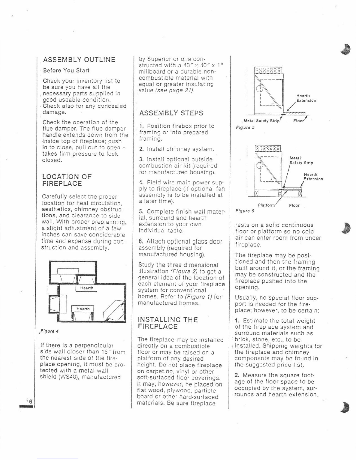
LOCATION OF
FIREPLACE
Carefully select the proper
location for heat circulation,
aesthetics, chimney obstructions, and clearance to side
wall. With proper prepianning,
a slight adjustment of a few
inches can save considerable
time
and
expense during
con-
struction and assembly.
If
there is a perpendicular
;ide wall closer than
15"
from
:he nearest side of the
fire]lace opening, it must be pro.
ected with a metal
vial1
jhield
(WS4O),
manufactured
by Superior or one constructed with a
40"
x
LO"
x
1"
millboard or a durabls noncombustible rnateriai
,with
equal or greater insulating
value (see
page
21).
ASSEMBLY STEPS
I.
Position firebox prior to
framing or into prepared
framing.
2.
Install chimney system
3.
Install c?!ional cu:side
combustion air kit (required
for manufactured housing).
4.
Field wire main power supply to fireplace
(if
optional fan
assembly is to be installed at
a later time).
5.
Complete finish wall material, surround and hearth
extension to your own
individual taste.
6.
Attach
optional
glass
door
assembly (required for
manufactured housing).
Study the three
dimensional
illustration (Figure
2)
to get a
general idea of the location of
each element of your fireplace
system for conventional
homes. Refer to
(Figure
1)
for
manufactured homes.
INSTALLING
THE
FIREPLACE
The fireplace may be installed
directly on a combustible
floor or may be raised on a
platform of any desired
height. Do not place fireplace
on carpeting, vinyl or other
soft-surfaced floor coverings.
It may, however, be placed on
flat wood, plywood, particle
board or other hard-surfaced
materials. Be sure fireplace
Haanh
Plalrom
'
Floor
Figure
6
rests on a solid continuous
floor or platform so no cold
air can enter room from under
fireplace.
The fireplace may be positioned and then
the framing
built around it, or the framing
may be constructed and the
firepiace pushed into the
opening.
Usualiy, no special floor support is needed for the fireplace; however, to be certain:
1.
Estimate the total weight
of the fireplace system and
surround materials such as
brick, stone, etc., to be
installed. Shipping weights for
the fireplace and chimney
components may be found in
the suggested price list.
2.
Measure the square footage of the floor space to be
occupied by the system, surrounds and hearth extension
Page 6
3.
Note the floor construction
i.e.
2
x
6's.
2
x
8's or 2 x 10's.
single or double joists, type
and thickness of floor boards.
4.
Use this information and
consult your local building
code to determine
if
you need
,additional support.
CAUTION: DO NOT BLOCK
,
THE HEAT CIRCULATING
AIR INLETS AND OUTLETS.
DOING SO MAY RESULT IN
A POTENTIAL
FIRE
HAZARD.
.If you plan to raise the fire-
place and hearth extension,
build this platform assembly,
'then position fireplace and
;hearth extension on top.
TO
INSTALL:
Step
1:
Slide fireplace into the
prepared framing, or
positlon
fireplace
in its final location
for framing later.
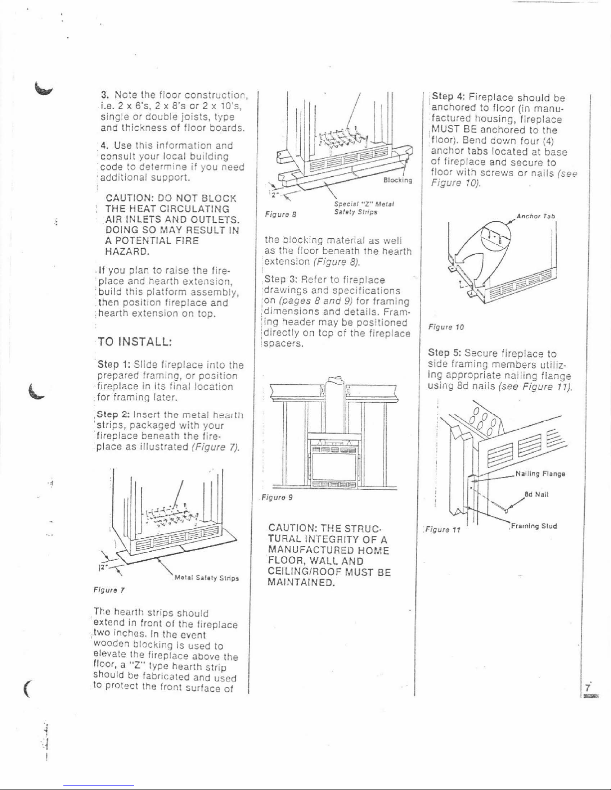
.Step
2:
Insert the metal hearth
'strips, packaged with your
fireplace beneath the fire-
place as illustrated
(Figure
7).
Figure
7
The hearth strips should
exlend in front of the fireplace
,two inches. In the event
wooden blocking is used to
elevate the fireplace above
the
floor,
a
"2"
lype hearth slrip
Should be fabricaled and used
10 protect the front surface of
the blocking material as well
as the floor beneath the hearth
extension
(Figure
8).
Step
3:
Refer to fireplace
:drawings and specifications
on
(pages
8
and
9)
for framing
dimensions and details.
Frarning header may be positioned
:directly on top of the fireplace
!spacers.
Figure
9
CAUTION: THE STRUC.
TURAL INTEGRITY OF A
MANUFACTURED
HOME
FLOOR, WALL AND
CEILINGIROOF
MUST
BE
MAINTAINED.
Step
4:
Fireplace should be
'anchored to floor (in manu-
factured housing, fireplace
.MUST
BE
anchored to the
floor). Bend
do~n four
(4)
anchor tabs located at base
of
f~replace and secure to
floor with screws or nails
(see
Figure
70).
Step
5:
Secure fireplace to
side framing members utilizing appropriate nailing
fiance
using 8d nails
(see
Figure
17).
!
Nalllng
Flange
!
:Figure
17
,Framing
Slud
Page 7
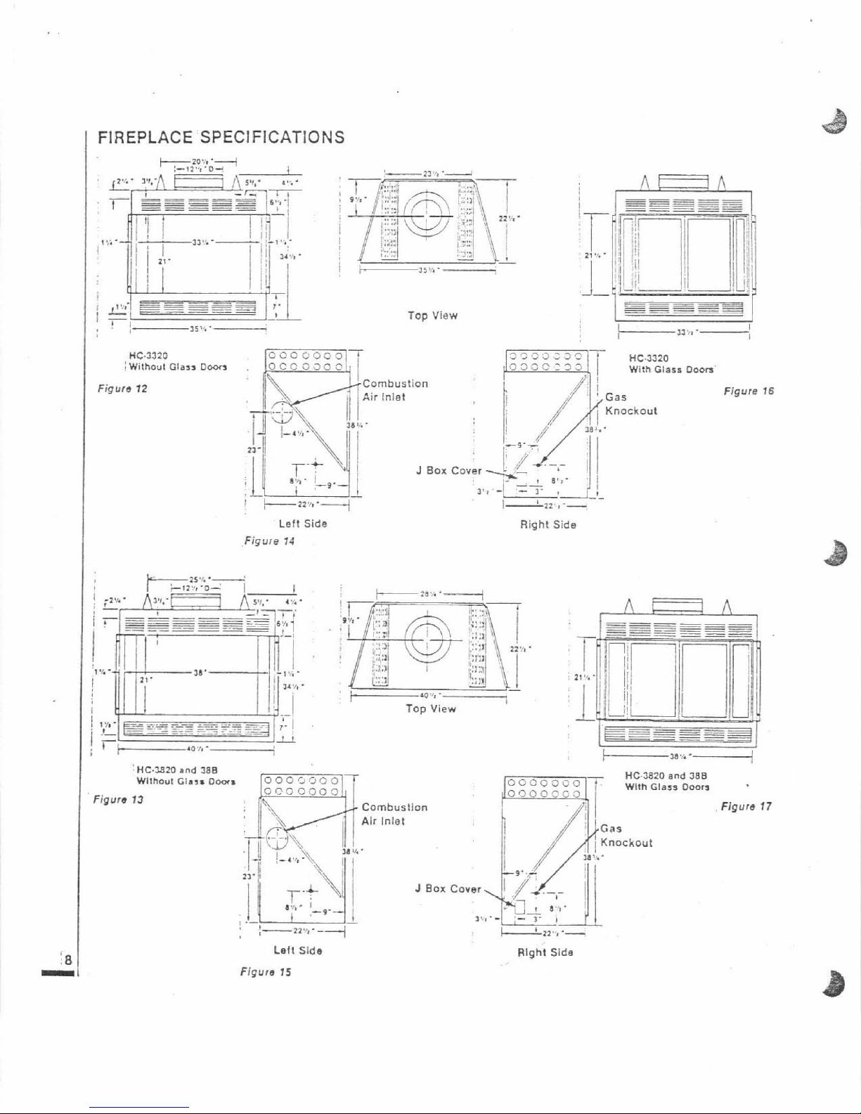
FIREPLACE
SPECIFICATIONS
?---
21
'+
'-
-----
A
i.
----
----
-
-
-
Top
View
--a
IS".'
!
I
J
Box
Left
Side
Figure
14
Figure
'HC.3820
and
388
Wltheut
Glass
Doas
,
13
HC.3320
0350333
With
Glass
I-
>>'>.-.
Doo"'
Figure
16
1C.',
Top
View
Lell Side
Flgurs
15
Right
Side
Combustion
Alr
lniet
J
Box
:
;-22,,,.-
i
HC-3820
and
28B
\
With Glass
Dm*
Right
Slda
Figure
17
Page 8

FRAMING
SPECIFICATIONS
+A--5
Fireplacs Framing
Figure
18
'If
Wall
Is
Inside
Usa
!T09.4
or
708-6
Adaolsr
AK.40,
AK.6
With
Combustion
At,
Kit
7
/
I
LA-
E-
108.4,
TOE-6
(Corner lnslallation)
I
(Oulalda
Chase)
Flgore
m
AK.4
Ol
AK-8
Combuolion
Air
KII
H
Mln.
Ceiling
Framing
(insids
Chase)
Figure
21
Figure
22
HC
AND
B
FRAMING
DIMENSIONS
40%
"
23%
"
28!&
"
11
"
14'/8"
6a'/~"
73'i,
"
34%
"
36'1,"
G
22?1
"
22
5'2
"
H
Without
3"
3"
H
With
'
8
"
8"
FRAMING DIMENSIONS
FOR CEILING
Ceiling
Opening
Type Flue
TF8,
Vanical
14'/~" 14%
"
TF8. Offset
30'
(Offset
applied
Only
to
ceiling
14'/2
"'
25"'
'Combustion
Air
Kil
I
AK-4,
AK.6
1
Figure
2.3
:FRAMING DIMENSIONS
FOR
ROOF
Roof
Opening
Page 9
INSTALLING THE
CHIMNEY SYSTEM
Step
1:
Check flue damper for
proper operation. When the
damper is in a closed
posi-
,tion, the damper blade should
be UP and the damper control
lever pushed all the way to
the rear of the firebox. When
the damper is open, the damper blade is DOWN and damper control lever is pulled ail
the way to the front of firebox.
Note:
In
Manufactured
Housing,
lireplace
MUST
BE
anchored to the floor. (Figure
10)
illustrates the seismic
anchor tabs
built into the fire-
place. (Figure
10)
illustrates
the proper installation technique.
-
.-
.
Nail to floor
as, shown.
Step
2:
Using standard construction techniques, frame
openings for chimney route
up through
ceiling(s) and roof
or through outside chase.
Framing must maintain ade-
quate support at all times.
CAUTION: ALLOW MINIMUM
1"
CHlhlNEY CLEARANCE
TO
COMBUSTIBLE FRAMING
MEMBERS THROUGHOUT
VERTICAL OR OFFSET CHIMNEY INSTALLATION.
;Reference (Figures
22
and
231,
'and charts "Framing Dimen.
sions for Ceiling and Roof."
which detail minimum ceiiing
and
roof opening dimensions.
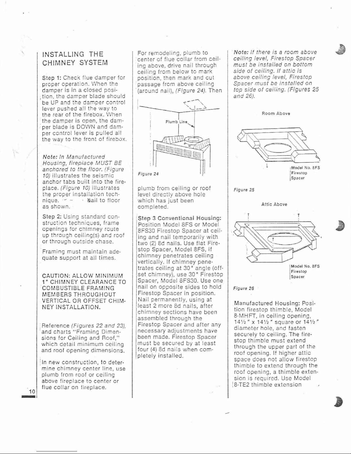
For
remodeling,
plumb to
center of flue collar from ceiling above, drive nail through
ceiling from below to mark
position, then mark and cut
passage from above ceiling
(around nail), (Figure
24).
Then
~n
I
--?
Plumb
Line
jln new construction, to deter.
mine chimney center line, use
plumb from roof or ceiling
above fireplace to center or
flue collar on lireplace.
plumb from ceiling or roof
level directly above
hole
which has just been
completed.
Step 3 Conventional Housing:
i~osition Model 8FS or Model
j8~~30 Firestop Spacer at ceil-
ing and nail temporarily with
two
(2)
ad nails. Use flat Fire-
stop Spacer, Model
8FS,
if
chimney penetrates ceiling
vertically.
If
chimney pene-
trates ceiiing at
30'
angle (off-
set chimney), use
30'
Firestop
Spacer, Model 8FS30. Use one
nail on opposite sides to hold
Firestop Spacer in position.
Naii permanently, using at
least
2
more 8d nails, after
chimney sections have been
assembled through the
Firestop Spacer and after any
necessary adjustments have
been made.
Firestop Spacer
I
must be secured by at least
four
(4)
8d nails when com-
pletely installed.
thimble to extend through the
roof opening, a thimble extension is required. Use Model
!8-TE2 thimble extension
Note:
If there is a room above
.&
ceiling level, Firestop Spacer
must be installed on bottom
side of ceiling. If attic is
sbove
ceilifig level, Firesfop
Spacer must be installed on
top side of ceiling. (Figures
25
and
26).
Room
Above
I
Model
No.
8FS
lFirertop
Ispacer
Figure
25
Attic
Above
lModel
Na.
BFS
Firerlw
Spacer
Figure
26
Manufactured Housing: Position
firestop thimble, Model
8.MHFT, in ceiling opening,
14%" x 14'/2"
square or
14%"
diameter hole, and fasten
securely to ceiling. The
firestop thimble must extend
through the upper part of the
roof opening. If higher
attic
saace does not allow firestop
Page 10

manufactured by Superior
Fireplace Company to extend
firestop thimble to proper
length. (Figure
27)
illustrates
typical
firestop tnimble instal.
lation. (Figure
281
shows an
installation requiring the
8-TE2 thimble extension. The
thimble extension slides over
the
firestoo thimble for a max-
imum
30"
combined height.
After determining proper
:height, fasten with four sheet
metal screws where the two
thimbles overlap (Figure
23).
Screws are provided with the
8-TE2 thimble extension.
Step
4:
Note: Chimney sec-
tions
are constructed with a
unique locking !ab design
whichi!suresan immediate,
tight
zssembly between sec-
tions. Plan your chimney
requirements
c~refully before
assembly as chimney is
difiicui: to disassemble after
installation.
The
TF8 Chimney System is a
two piece chimney, which
snaps together from the fire-
place up.
Start
viith the inner flue sec-
tion. With the hemmed end
Lacking
TrimtoFitROaf
Flashing
BMHT
Figure
27
,,,
I
Outer pipe section installs in
just the opposite way; the
hemmed end goes
UP
and
each new section goes
OVER
the outside of the previous
section installed. (Figure
30).
Note:
Assemble one complete
section of chimney at
a
time
(inner section first, then outer
seclion last) before proceed-
ing
with the next complete
section. Continue to build flue
pipe assembly up through
framed ceiling openings and
roof frame opening. Assemble
just enough to penetrate the
roof and flashing openings
(Figure
31).
Always maintain
1"
minimum clearance to
combustible materials and
always check each pipe joint
:(inner and outer) to insure pro:per engagement. Check verti,cal alignment of flue pipe so
;that it projects the roof in a
;true vertical position.Use--.
level
if
necessary~o-ks~~qrel.
'proper vertical position.
Superior chimney sections
need not
be
screwed together
for additional reinforcement.
down, snap lock it to the
matching locking flue collar
on top of fireplace. At all subsequent joints, the upper
piece fits inside of the lower
piece. Each piece snaps
togetker and locks by means
of locking tabs
(9
locking tabs
per joint). Check each piece
to
insure~proper ensagernent,
beioie
installing preceding
section by pulling slightly
from the top. If the chimney
section has been installed
correctly, it will not separate
[when you test it. Also, the
chimney joint where each
section is joined should be
;tight and flat with no gaps
(Figure
29).
Flgure
28
Page 11

Clearance
lo
Cornbusl~ble~
RJn9.
Fnr
M.nr,f2r+r,mrl
.
n+nd
t-+n.inisrrrrtte&a9L--
Housing: The chimney sec-
tions can be installed in any
sequence, by length; however,
there are two important
considerations:
71
If two sections of chimnev
rrrru iu
ur
ju~firo iuyrriirr
inside the thimble, join the
sections first before inserting
through the thimble.
2)
The height of flashing and
chimney sections which pro-
ject above the
roofline shall
not exceed
13'6"
from ground
level for transporta
tion pur-
poses. In (Figure
32).
it is
assumed the floor level of the
Manufactured Home is
30"
above the ground.
Step
5:
The heignt of vertical
flue pipe supported oniy by
the fireplace must not exceed
30
feet. Flue heighls above
30
feet must be supported by a
Model 634 unitized stabilizer
installed at 30 foot intervals.
2
I
Note: The Model
8-S4
unitized
stabilizer adds
2%
inches net
effective height to the total
chimney system.
Figure
32
Install the model
8-54
stabili-
zer by fitting inner section
down into respective section
of preceding flue pipe and
locking outer stabilizer section into place over the outer
flue pipe. Position for proper
clearance through framed
opening and nail straps
securely (under tension, in
"shear") into place on framing. Use
8d
nails. Attach
successive lengths of flue
pipe directly to stabilizer
using same technique as
described
in Step
3.
Note:
Do
not apply excessive
pressure to any subsequent
chimney sections following
the stabilizer when installing.
Insure each subsequent chimney section is securely
attached, however, by testing
as noted in Step
4.
Step
6:
Select proper Superior
roof flashing, depending on
the pitch of roof. Use chart
below for selection:
[
Roof Pitch
I
Model
]
-
---z
*--I-
-L--,..L-
...A
...,
Next, slide roof flashing over
extended chimney section
that previously had been
instalied above the roof opening in Step
4.
Slide flashing
all the way down until the
fLa,s,hi!g3,?,%
r~L~,f/$?eOfl,Eh,B
position of the chimney and
the
I'
minimum clearance to
combustibles.
Figure
34
Step
7:
Secure flashing by
nailing along perimeter into
roof using
8d nails. If shingled
roof, slide upper end and
sides of flashing under
shingles (trim if necessary)
(Figure
34%
seal the top and
both sides of the flashing to
the roof with roof caulking.
Cover nail heads with roof
caulking.
Page 12

b
.Step
8:
The standard Superior
:roof flashing assemblies
;include a storm collar. Slide
jstorm collar over outer flue,
align with top surface of
flashing, insert storm tab in
I
Slot, pull tight and bend tab
i
back over slot. Seal storm
1
collar to outer flue pipe with
:roof caulking or mastic
/
around entire circumference
j
of pipe. (Also add extra roof
caulking where storm collar
meets flashing and to the
tablslot area to seal completely against water penetra.
:tion (Fioure
35).
Check all
-
joints
very
carefully
tb
insure
'no water intrusion can take
,place.
Step
9:
Superior locking
bands (Model
8LB)
may be
required
if
chimney extends
too high above the
roof1
flashing.
As
a general rule,
if
the chimney extends more
than
6
feet above the roof1
flashing, the use of locking
bands is advisable to
strengthen the chimney joints.
Ali~n locking band (one per
pipe joint) at the pipe joint
-
locking band wraps around
pipe joint, equally covering
the joint of
both 3ipe sec-
tions. Use nut provided and
TIGHTEN snugly. Do not over
tighten as this nay
damage
flue section (Figure
36).
!
Step
10
Conventional Homes:
If
using a CTD round contem-
porary termination:
1)
Hold CTD over top of last
chimney section (Figure
38).
2)
Center inner slip section
into inner flue
pipe - slip
down.
3)
Center outer locking sec
tion over outer flue nine
-
?-
iecklng
Band
push down until locking joint
snaps into position.
4)
Pull up slightly on CTD to
insure locking joint has firmly
engaged.
1
Note:
If
chimney extends
more than
s
feet above roof
line, guy wires are also
recom.
mended. Use fhree
(3)
guy
wires, attach to locking band
assembly, extend end secure
to roof in a triangular paftern
.(Figure
37).
Guy wires not sup-
plied
by
Superior.
Figure
38
w
Using a CT1 Chase
Termination
Note: Refer to specific instal-
lation instructions
~ncluded
viifh
CT7
chase termination
for
deta~is.
Manufactured Housing
Note: Complete and inspect
instaliation Steps
i
fhrough
9
as required prior to shipment
from factory. Step
10,
install-
ing the
termination, will be
completed
after the manulaclured home has arrived at the
instaliation site.
Page 13

'Always cover exposed chim.
ney sections with water proof
protection for storage and
transportation between
fac.
tory and installation site to
prevent rain and other foreign
matter from collecting inside
the fireplace and chimney.
Remove this protective covering immediately prior to
installing the termination.
Failure to do so will create a
fire hazard should the chimney sections and its cooling
system become blocked.
:The TF8-MHT mobile home
;termination adds 17%" effec.
tive height to the installation.
Use this dimension to determine
if
additional chimney
sections are required. Provide
a safe and legal
termination
height. Consult the ten foot
rule summary section on this
page for detailed information.
To install the
TFG-MHT
Manufactured Housing Ter-
mination, slip the termination
onto the preceding chimney
section. Wrap the locking
band, Model 8-MHLB, around
the joint and fasten securely
with the nut and bolt provided
'(Figure
39).
Figure
40
TEN
FOOT
RULE
MULTIPLE
SUMMARY
TERMINATIONS
The minimum chimney height
,above the roof is specified by
all major
U.S.
building codes.
If the horizontal distance from
the chimney
edce to the peak
'of ihe roof is more than 10
feet or less, the top of the
'chimney must be at least
2
feet above the peak of the
roof.
If the horizontal distance from
the chimney edge to the peak
of the roof is more than
10
feet, a chimney height refer-
ence point is established on
the roof surface
10
feet hori.
zontally from the chimney
'edge. The top of the chimney
must be at least
2
feet above
this reference point. In all
cases the chimney cannot be
less than
3
feet above the
roof at the edge of the
chimney.
!The
2'
in
10'
rule is necessary
'in the interest of safety and
Jdoes not insure.smoke-free
operation. Trees, buildings.
adjoining rooflines, adverse
wind conditions, etc.. may
require a taller chimney
should the fireplace not draft
properly (see Figure
40).
If more than one termination
is located on the same chase
or within the same general
proximity, we suggest they
'should be separated in dis-
tance at least
24"
horizontally
from
flue center to flue center
and stacked, or soldiered
vertically at least 18" apart, from
termination smoke exit to
termination smoke exit. See
(Figure
41)
for detail.
:This suggestion is in the
inter,est of better satisfactory oper:ation and use.
If
terminations
!are located too close to each
other, smoke may migrate
from one flue into the other.
I
Figura 41
Page 14

.TF8 CHIMNEY
'COMPONENT
iCALCULAilONS
I
iMinimum installed height of
'the
HC
and B series fireplace
!systems (including fireplace
!and chimney components) is
!12'0" in conventional homes
:and 12'0" in manufactured
.housing. The maximum height
:is
80' in conventional hones
and 20'0" in manufactured
,housing.
lation. This
dimension
is the
,distance
from the
FLOOR
the
fireplace
Sets on to the point
where smoke exits from the
term~nation.
.2.
Determine the number of
:chimney components required,
except chimney sections. This
would include firestops,
stabi-
I
lizers, roof flashing, etc.
3.
The effective heights of the
components are:
HCand
B
Series
Fireplaces
=
38"
4.
Determine amount of chim;ney height required by sub*tracting total combined height
I
!of all preselected components
(fireplace and chimney com-
ponents) from total desired
i
height.
Reference Vertical Elevation
Chart and determine number
:of chimney sections (quantity
,and length) required.
I
MANUFACTURED
HOUSING
VERTICAL ELEVATION CHART
CONVENTIONAL HOMES
:To determine the number of
chimney sections and chimney components required,
;follow these steps:
7.
Determine total vertical
[height of the fireplace
instal-
jorder separately.
'C~~~ermination
=
4"
CTi Termination
=
18"
'54
S!abilizer
(required for every
30'
of vertical chim-
:ney and 10'of
(offset chimney
=
21/>
Use Model TFB.MHCP.1 which
'contains all chimney
compon-
Ients and chimney sections
fo;
typical manufactured housing
,installations. It provides for
;an installed height
of
12'2".
If
;additional chimney sections
!or components are required,
Page 15

I
'OFFSET CALCULATIONS
1.
Use Offset Charts to deter-
mine amount
of horizontal off-
set
(A)
and height
(B)
for
various flue pipe section
assemblies.
2.
Use "Height of Flue Only"
column on Vertical Elevation
Chart to determine combinations of pipe used above
return elbow to achieve
desired heights. Reference
components effective height
chart in vertical elevation
chart section.
,
,
3.
To use Elevations Chart as
job estimator only; add
neces.
sary firestop spacers and stabilizers, as required.
Firestop
spacers must be used as
shown in
(Figures
25
and
26)
and stabilizers as shown in
(Figure
33).
*
I
TFO.E30
111
Refurn
Elbow
I
Chmnay
Sections
Ollsel
Elbow
I
OFFSET ELEVATION
CHART
Page 16

Q
OFFSET
INSTALLATIONS
Special Offset Instructions
To clear any overhead
obstructions, you may offset
your chimney system using
Suoerior
30"
offset and return
elbows (Models
TFB-30 and
TFB-E30).
Use two elbows - an offset
.elbow to initiate the offset
and a return elbow to
terni-
nate it.
The offset and return elbows
may be attached together, or
a section or sections of chimney in between may be used,
but do not exceed
20'
in total
length between elbows (see
Figur2
43).
If
sections of pipe
exceed
i0'
between elbows, a
chimney stabilizer must be
used at the
10'point. The sta-
bilizer
support straps must
be
securely attached under ten.
sion (in shear)
!o structural
framing members above (see
Figure
d3).
Vlhen two sets of
elbows are used, the
maimum combined lsngth of
chimney used
between each
set of elbows cannot exceed
20'
(see Figures
44
and
45).
Example: If
C,
=
iO'then
C,
'cannot exceed
10'.
A
30" off-
set elbow, angling in any
direction, may be the first
component used off the top of
the
fire~lace flue collar.
~
~~
needed for your
Maximum offset of chimney
and purchase
system is
30".
TVJO offset
1,
before beginning insfaliation.
'elbows must not be assem,bled to form a
60°
offset.
Figure
43
I
Figure 44
Figurs 45
However, two sets of offset
and return elbows
nay be
used in
a
single flue system,
provided the total
heigh: of
the system exceeds
25'.
1
Return elbow support straps
must
be securely attached
under tension (in shear) to
structural framing members
:above (Figure
46
Page
78).
Note: The TF8-MHCP-1 Manu-
'faclured Housing Chimney
Pack does not contain any
offset or return elbows
to
i
facilitate offset chimney
!
instailation. Calcuiate the
!additional
chimnev com-
1
Page 17

TO INSTALL
OFFSETS
First. review chimney offset
elevation chart and Figure
42
on page
76
for reference.
:step
1:
Determine the offset
distance where flue is to pass
through the first ceiling
-
dimension
"A".
To find lhis
point on your ceiling, first
determine the centerpoint for
'a vertical chimney following
the instructions for vertical
installation.
Measure height to the ceiling
from top of fireplace
-
dimen-
sion
"0".
Use offset Elevation
Chart to find dimension "A".
Mark point where you
will
drive your nail to show the
centerpoint for your offset
ceiling cut.
Step
2:
Proceed by using the
Straight Up
Instailation
lnslructions for cutting and
framing ceiling and roof
openings.
Note: See
Fram~ng and
Dimension Chart for the sizes
of the ceiling and roof openings. The size of the roof
opening varies with the
degree of the pitch of the
roof.
OFFSET ELBOW
ASSEMBLY
IFBE30
Return
Elbow
18
-
Figure
46
Offset elbows install the
same as chimney sections.
First, snap the inner section
INTO the preceding inner sec-
tions of chimney. Check connection by pulling slightly to
insure a tight fit. Next, the
outersection snap locks
OVER the preceding outer
section of chimney. Again,
'check outer
sectlon by pulling
'slightly to insure proper
connection is made.
RETURN
ELBOW
ASSEMBLY
Return eibows ins!ail the
same as stabilizers and round
contemporary terminations.
Follov~ these easy steps:
1)
Hold unitized return elbow
over top of last chimney
section.
2)
Center inner slip section
into inner flue pipe
-
slip
down.
3)
Center outer locking sec-
tion over outer flue pipe
-
push down until iocking joint
snaps into position.
4)
Pull upsljghtly on return
elbow-to
insu~Velocking joint
has firmiy engaged.
Remember, all offset and
return elbows and any chimney in between must be
installed to maintain at least
1"
clearance to combustibie
materials.
Note: Do not apply excessive
pressure to any subsequent
chimney sections following
return elbow assembly when
Installing. Insure each subsequent chimney section is
securely attached, however,
by testing as noted above.
CHIMNEY
OFFSET
30'
THRU FLOOR OR
CEILING
It may be necessary to construct the chimney at
30"
when passing through the
floor or ceiling area.
Use
30"
angled firestops as shown in
(Figures
47
and
43).
Support
the chimney at floor or ceiling
penetration
with stabilizer if
distance below the ceiling is
10'
or more. Maintain
1"
mini-
mum clearance to
conbust.
ibies from chimney sections.
Attic
space
BFS30
8%
Slabilirer
10:
Mar.
/
30'
Fire9lop
And Altic
Above
Figure
47
-,
10'
Max.
/
30'
Firattop
and
Rocm
Abors
Figure
48
Page 18

ACCESSORIES
Glass Doors Optional For
Conventional Homes
-
Required For Manufactured
Housing
If glass doors are to be
installed on this fireplace,
refer to specific installation
instructions packed with glass
doors. Superior glass doors.
-.::
'Model Numbers 33HGD-AB,
:38HGD and 38HGD-A9 are for
'use only on certain Superior
factory-built fireplaces.
Use on
any other fireplace may con-
'stitute a potential fire hazard.
Glass and metal frames
get
hot - always use wood
'handles to
oaen and close.
Glass doors are required for
installation in all manufactured home installations to
.cornply with Federal HUD
Q
:requirements.
COMBUSTION
(FRESH)
'AIR
SYSTEM
OPTIONAL
'FOR
i
CONVENTIONAL
-
:REQUIRED
FOR
MOBILE
;HOME INSTALLATION
-?
In Conventional Homes:
Use Combustion Air Kit Model
AK.4
with Superior HC and
B
fireplaces.
In Manufactured Housing:
Combustion Air Kit Model
AK-6 must be installed with
the Superior HC or
8
fireplace
to comply with Federal HUD
'requirements.
i
GENERAL
INFORMATION
Outside alr drawn into the
fireplace
suppltes alr to the
fire for combustion. Only one
combustion air duct on left
side of the fireplace is
required, if
ins:alled.
Figure
49
1
If additional length of duct is
:required, use locally available
;U.L.
Class
1,
aluminum
iducting. The duct may be
!extended
up
to
50'
in any
/direction.
I
I
Note: Do not terrn~nate corn-
bustion air kit rn attic space.
'There
is
one hand operated
shut-off damper at the left of
the firebox opening inside the
'fireplace. To open, pull out all
:the way. The combustion air
'damper should be fully open
/when the fireplace is being
:operated. When the fireplace
'is
not in use, fully close the
combustion air damper to pre-
;vent cold air from entering
your home.
TO INSTALL:
Reference installation instruc-
tions supplied with Models
,
AK-4 or AK-6.
Never locate inlet where it
can be blocked by shrubs,
snow drifts, etc. Never locate
in garage or any area where
.
there is another fuel burnlng
appliance or products emit-
tlng combustible gases such
I
as Paint, gasoline, etc. In cold
cltmales, it is recommended
that the combustion air duct
be insulated.
Outside combustion air
ducting may be installed
upwards, or vertically, through
framing and ceiling joists,
with the hood installed
through an outside wail or
ducting may be installed
downwards, through floor
joists, and under the floor of
the home. Ducting may be
installed into a basement
area, not considered part of
the living area or the home.
Figure
50
Figure
51
FORCED AIR KIT
If you are installing a Superior
Forced Air Kit. Model
FAK-1500, see the instruction
sheet provided in the kit for
electrical wiring requirements.
The fireplace has been prewired at the factory to accept
the forced air kit at some later
time. The fireplace must, however, be connected to main
power supply at time of installation
if
the FAK-1500 is to be
installed later.
Page 19

FIREPLACE FINISHES,
HEARTH
EXTENSIONS,
WALL
SHIELDS
I
FRAMING
Ilt's best to frame your fire!place after it is positioned.
:the chimney and the
ccmbus.
tion air kit,
if
applicable, is
/installed. Frame with
2
x 4's
:(or heavier) lumber. Frame in
accordance with local
prevaii-
ing building codes.
Note:
The header may rest on
!he top metal spacers, but
must
not be notched to lit
around them.
No clearance is required
,between the framing and
f~re.
'place and thimble (for manu-
factured housing use only).
However, remember a
1
"
clearance is required between
framing and the chimney.
To install the fireplace facing
flush with the finished
\vall,
position framework to accommodate the thickness of the
finished wall (Figures
52.
A,
5
I
'and
C).
To insta!l the fire?!ace facin~
flush vit3 sur:ou-d materials.
0osi:ion framework to accorn-
'modate the thickness of the
final
surroun materials
(Figure
52
D).
\
Flnirh
Wall
Oimenrion
Figure
53
GAS LINE
This provision
is
intended for
connection to a decorative
gas appliance only, in accordance
wirh the National Fuel
Gas Code,
ANSi Z 223.1-i960.
If you're installing a gas line,
concect it now. The gas
knock out location is determined by a
1
118"
round
indentation located at the
bottom and slightly off center
on the side refractories. THE
KNOCK OUT
IS
ALWAYS TO
BE
REMOVED
FROM
INSIDE
THE FIREBOX.
If
removal is
attempted
!rom the outer
wrapper
into the firebox, side
'refractory damage may occur.
With a medium-sized hammer,
lightly tap the surface of the
indentation. The refractory
material is very thin in the
area of the indentation, and
can be easily removed. Once
a small hole is made in the
knock out, continue to tap
lightly until the desired diameter is obtained. The knock out
area can be removed to a
total diameler of
1
118"; however, the entire knock out
does not have to be removed.
With the refractorv knock out
removed
:o the disired diarneter, remove knock out on
outer wrapper and install gas
line. Use only
'/2"
black iron
pipe through fireplace wall for
cocnection to a
106 lighter or
gas log unit inside
the firebox. Outside, the iron pipe
connects to a gas shut
o:i
valve recessed flush into a
wall or floor and controlled by
a removable valve key for
safety.
Always plumb gas line instal-
lation pe: state and local
codes. Check all connections
with soa9 suds; leaks will
bubble. Never test any gas
line connections with a match
or open flame.
IMPORTANT: Re-pack
insuiation in square hole around
gas line to seal.
CAUTION: WHEN USING THE
DECORATIVE GAS APPLI-
ANCE.
THE FIREPLACE
DAMPER MUST BE SET IN
:THE FULLY OPEN
POSiTlON.
COLD CLIMATE
INSULATION
If
YOU
live in a cold climate,
seal
all cracks around fire.
place with
non-combustib!e
material and wherever cold air
could enter room. It's espe-
cially important to insulate
outside chase cavity
Setsveen
studs and under floor on
which fireplace rests, if floor
of outside is above ground
level. Surround material must
be caulked where it meets
[he
black metal face of the fireplace to avoid air intrusion.
Use non-combustible caulking
mater~al only on fireplace
facing, to seal. Also the out.
side air inlet duct should be
insulated to minimize formation
of
condensation.
Page 20

HEARTH EXTENSIO NSI
WALL SHIELDS
*A hearth extension must be
installed with all
firep!aces. It
.is required !o protect :he floor
in front of the fireplace from
both radiant heat and sparks.
-The hearth extension must
extend beyond the front and
both sides of the fireplace
opening per the dimensions in
the chart
accompanyir,g (Fig-
ure
54).
Use either the metal
hearth extension
(Modsl HE-33
for HC-3320 or Model HE-36 for
.HC-3820 and 368) manufac;lured by Superior Fireplace
Company, or a
'It
"
thickness
!of millboard or a durable non-
combustible material
with
equal or greater insuiatirg
value. These materials may be
covered by a decorative
nan-
combustible veneer.
CAUTION: FIREPLACE MUST
BE RAISED IF HEIGHT OF
:HEARTH EXTENSION
EXCEEDS
I'll"
ABOVE
:BOTTOM OF FIREPLACE
:(FIGURE
55).
'*If
fireplace is installed on a
,combustible floor, use
:he
,metal safety strips (provided)
on the floor, extending half
'under the fireplace and half
under the hearth extension.
BETWEEN THE FIREPLACE
AND HEARTH
EXTFNSIAN
I
NON-COMBUSTIBLE
MATERIAL.
I
INSTALLING THE HEARTH
EXTENSION
BE
CAREFUL
*Secure the hsarth extension
to the floor to prevent
possi-
;
ble
shifting.
-If a side wall is closer than
15"
to the fireplace opening, a
wall shieid is reauired. Use
metal
wall shields (Model No.
:
WS4C)
manufactured by
Superior Fireplace Company or
construct
ia;i:h a
40" x 40"
x
1"
millboard cr a durable non-
combustible material
with
equal or Greater insulating
value. The wall shields may
b~
covered with a decorative non-
I
.
combustible veneer.
-
8
Figure
54
HEARTH EXTENSION
DIMENSIONS
Models
Letter HC.3300 HC.3800
'38"
I
8"
I
*If firepIace 1s Installed
dia-
,gonally, across a 90" corner,
Iflo wall sh~elds are requlred
((F~gure
12)
*For information regarding
non-combustible materials and
construction detaiis, contact
:Superior
Fireplace Company,
Customer
Senice Depar:ment.
Fi
PJlSH
TO
YOUR
TASTE:
There are a wile variety of
"finished looks" for your
'Superior fireplace
-
from for-
:ma1 ?.fall treatments to man
tels to rustic !.~ood paneling
to
warm brick facings.
I If you are uslng a combust.
i
ible material, do not overlap
the black
fireolace facing
(Fig.
,
ure
52)
I
I
FACING
AND
WALLSUR.
ROUNDS WITH A NON.
I
COMBUSTIBLE MATERIAL.
Max.
Thickness
ol
Hesnh
Extension
when
Figure
55
Fireplace
1s
on
FIOO~
Non.comtustible materials,
like tile, stone, brick, etc., may
overlap
the edge of the fire-
place opening,
thweon.r---
..
-
pletely-hiding the blackfire-
i
'placefacing; but be sure not
!to interfere with the operation
;of the glassdoor: See (Flgures
+16-md1-7)
for minimum front
facing dimensions if glass
doors are to be installed.
Page 21

SUPERIOR ACCESSORY
PARTS COMPONENTS
LIST
The following accessory parts
and components are to be
used only with your Superior
fireplace system. Separate
installation instructions all
packaged separately with all
glass doors, combustion air
Chimney
Ssst>on
TF8.35
Chimney
Ssclion
TF.18
Chimney
Secllon
TFB12
kits, forced air
fan
kits.
&ki~neytop terrnina:ions and the
manufactured hone
cF,imney
pack.
If you encounter any problem:
or have quesiions concerning
the installation or application
of this system, please
contact:
:
Fireslop
Spacer
(35'1
8FS3
Ollsal
Elbow
TFB30
Return
Elbow
TFBEIO
SUPERIOR FIREPLACE
COMPANY
Special Services Coordinator
4325
Artesia Ave.
Fullerton. California
92633
714-521.7302
Locking
B.t,td
8LB
Fleshing
Round
Te#rnlnatlon
TFbCTP
Page 22

Chase Terminallan TF8CTl
Thimble Ertenrlon BTE2
Chlmnay
Pack
Manulaclured
Hams
TF8.MHCP.l
Forced
Air Kil FAK.1500
t5
1 . TF8.CTD
Z
Firestop Thimble
(IHHFT
AK.4
Comburllon
AIr
Kit AK.6
Chimney
Pack
Canvanlidnai
TFa.CP7
108-4
Take
011
Boo1 Toe-6
3BHGD
33HGD.AB
Glars
Doers
33HGD.AB
Hearlh Extensions
HE46
Wall Shield
WS40
Relraclory Palch Kit
RPK
ReIra~twy Trlm
KI~
RTK
 Loading...