

Superior ARCHED FACE KITS SDVI, SDVI-A-BKN, SDVI-A-BRN, SDVI-A-B, H7016 Installation Instructions Manual
...Page 1
HEARTH PRODUCTS
KITS AND ACCESSORIES
P/N 506033-03
Rev. NC, 03/2008
INSTALLATION INSTRUCTIONS FOR INSTALLING ARCHED
FACE KITS FOR USE WITH THE SDVI GAS FIREPLACE INSERT
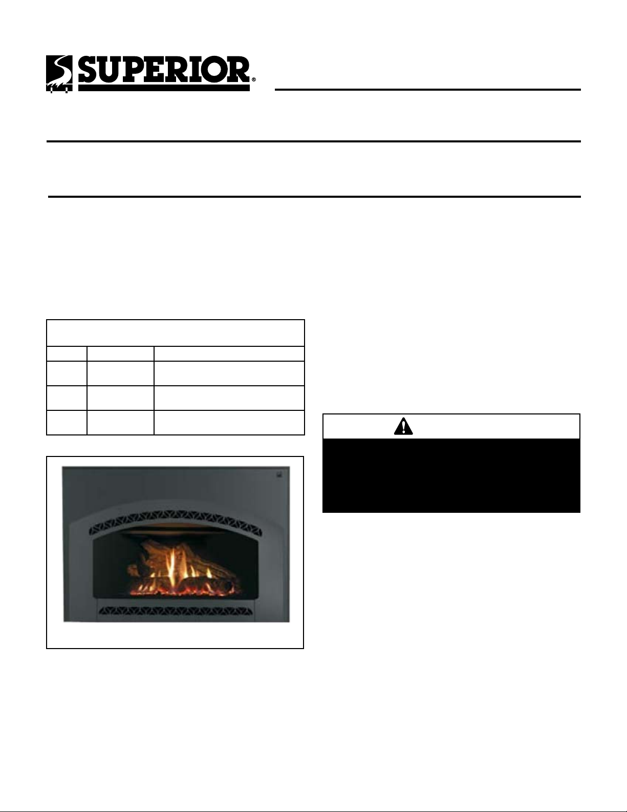
KIT CONTENTS (See Figure 1):
Please ensure that all these parts are in one of the two boxes.
1 ea. Surround Kit
1 ea. Surround Trim Kit
1 ea. Face Kit
1 ea. Instruction Sheet
Face / Surround Panel Kits
(Required) - Includes Black Face, Surround, and Black Trim
Cat. No. Model Description
H7016 SDVI-A-BKN
H7015 SDVI-A-BRN
H7014 SDVI-A-B
Arched Black Nickel Face,
Surround (27" x 39"), and Black Trim
Arched Brushed Nickel Face,
Surround (27" x 39"), and Black Trim
Arched Black Face,
Surround (27" x 39"), and Black Trim
ARCHED FACE KITS
MODEL SDVI
GENERAL INFORMATION
All of these parts may scratch and bend, great care should be used
in handling them.
If you encounter any problems, need clarification of these instructions
or are not qualified to properly install this kit, contact you local distributor or dealer.
Read this instruction sheet in its entirety before beginning the installation.
ALL WARNINGS AND PRECAUTIONS IN THE INSTALLATION AND
OPERATION MANUAL PROVIDED WITH THE APPLIANCE APPLY TO
THESE INSTRUCTIONS.
TURN OFF THE FIREPLACE AND ALLOW IT TO COMPLETELY COOL
BEFORE PROCEEDING.
IMPORTANT
Figure 1
TOOLS NEEDED:
Flat Bladed Screwdriver
Surround
Arched Face
Arched Face
If you have a gold or nickel face kit, be sure to clean
it with a soft cloth and household glass cleaner
prior to burning the insert. Fingerprints left on the
plated surfaces while burning will usually remain
on the finish permanently.
INSTALLATION INSTRUCTIONS
Surround Panels Installation
The SDVI insert surround panels are made of heavy gage steel for durability
and, if desired, for the ease of making an inside fit in the fireplace.
Step 1. Remove the speed nuts from the parts bag, supplied with the
insert (A in Figure 2) and install (with the flat surface forward)
on the six holes in the surround brackets - three on each side of
the insert (B in Figure 2). A flat bladed screwdriver may help in
installing the nuts.
NOTE: DIAGRAMS & ILLUSTRATIONS ARE NOT TO SCALE.
Page 2
Step 2. Install all surround panels and trim with the insert positioned in
the fireplace but a few inches in front of its final location.
Arched Face Installation
Step 3. Install the side surround panels by lining up the holes in the tabs
on the side surround panels in front of the holes on the surround
brackets. Next insert two slotted 1/4" truss screws for each side
surround panel and secure loosely.
Step 4. Fasten top surround panel with the remaining two truss screws.
Tighten all six truss screws after adjusting the surround panels
to eliminate space between side and top surround panels.
Step 5. Assemble the surround trim by inserting the elbowed retainer in
the rectangular slot in the ends of the longest piece of trim and
secure by tightening the screw in the retainer. Slide the mitred
ends of the two side trim pieces onto the elbowed retainer and
secure by tightening the retainer screw.
Step 6. The fastened trim pieces should now be horseshoe shaped. Slide
the trim down over the surround panels so the edge of the surround panel fits just behind the rounded edge of the trim.
Step 7. Install three spring clips (found in parts bag in firebox) in each
piece of trim by inserting them between the rear of the surround
panel and the channel of the trim. The spring clips will push the
trim tight to the surround panel.
Step 8. Remove the face from the box (see Figure 3) and place the face
down making sure that the side with the studs are facing upwards.
Be sure that the front of the face is lying on a soft non-abrasive
surface.
Step 9.
The sight obstructor is installed with the curved edge down and
the bent edge towards the insert. Slide the tabs on the obstructor
into the slots (D in Figure 2) in the surround brackets.
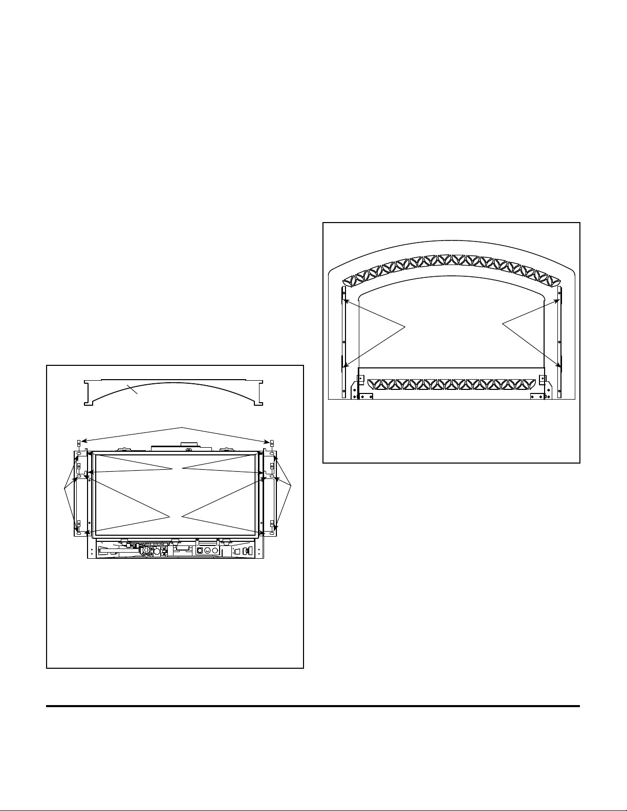
Step 10.Install the face onto the surround brackets at position C (shown
in Figure 2) and per the instructions in Figure 3.
The hooked brackets
identified here will hang
on the surround brackets
at position C shown in
Figure 2
Sight Obstructor (D)
A
D
B
C
A = Speed nuts
B = Holes in the surround brackets - three on each side
C = Location where hooked brackets on face will hang
D = Slots in the bracket that the sight obstructor goes into
The face has two hooks on each side that slide over and hang on the
surround brackets at position C shown here. The face can slide slightly
from side to side to center the face on the glass.
Figure 2
The face has two hooks on each side that slide over and hang on the
surround brackets at position C shown in Figure 2. The face can slide
slightly from side to side to center the face on the glass.
Figure 3
NOTE: DIAGRAMS & ILLUSTRATIONS ARE NOT TO SCALE.
Lennox reserves the right to make changes at any time, without notice, in design, materials, specifications, prices and also to discontinue colors, styles and products. Consult your local
distributor for fireplace code information.
Printed in U.S.A. © 2008 LHP
P/N 506033-03 Rev. NC 03/2008
LHP
1110 West Taft Avenue • Orange, CA 92865
 Loading...