

Page 1
HEARTH PRODUCTS
KITS AND ACCESSORIES
POLISHED BRASS OR BRUSHED STAINLESS
LOUVER KITS
INSTALLATION INSTRUCTIONS FOR POLISHED BRASS OR BRUSHED STAINLESS
LOUVER KITS FOR USE WITH LENNOX HEARTH PRODUCTS GAS FIREPLACES
GENERAL INFORMATION
These polished brass or brushed stainless louver kits may be used with
Lennox Hearth Products gas fireplaces, to replace the factory installed
black louvers. The kits contain seven louvers plus one louver with two
pre-drilled holes (eight total) and these instructions.
INSTALLATION INSTRUCTIONS
Step 1. Turn off the fireplace and allow it to cool before proceeding.
Step 2. Slightly lift and pull the existing top louver assembly away
from the fireplace.
Step 3. Slightly lift up the bottom hinged panel to disengage the
small hooks on ether side of the panel. Pull forward and lower the
panel down to open. Remove the assembly from the fireplace by
removing the hinge screw on each end of the assembly.
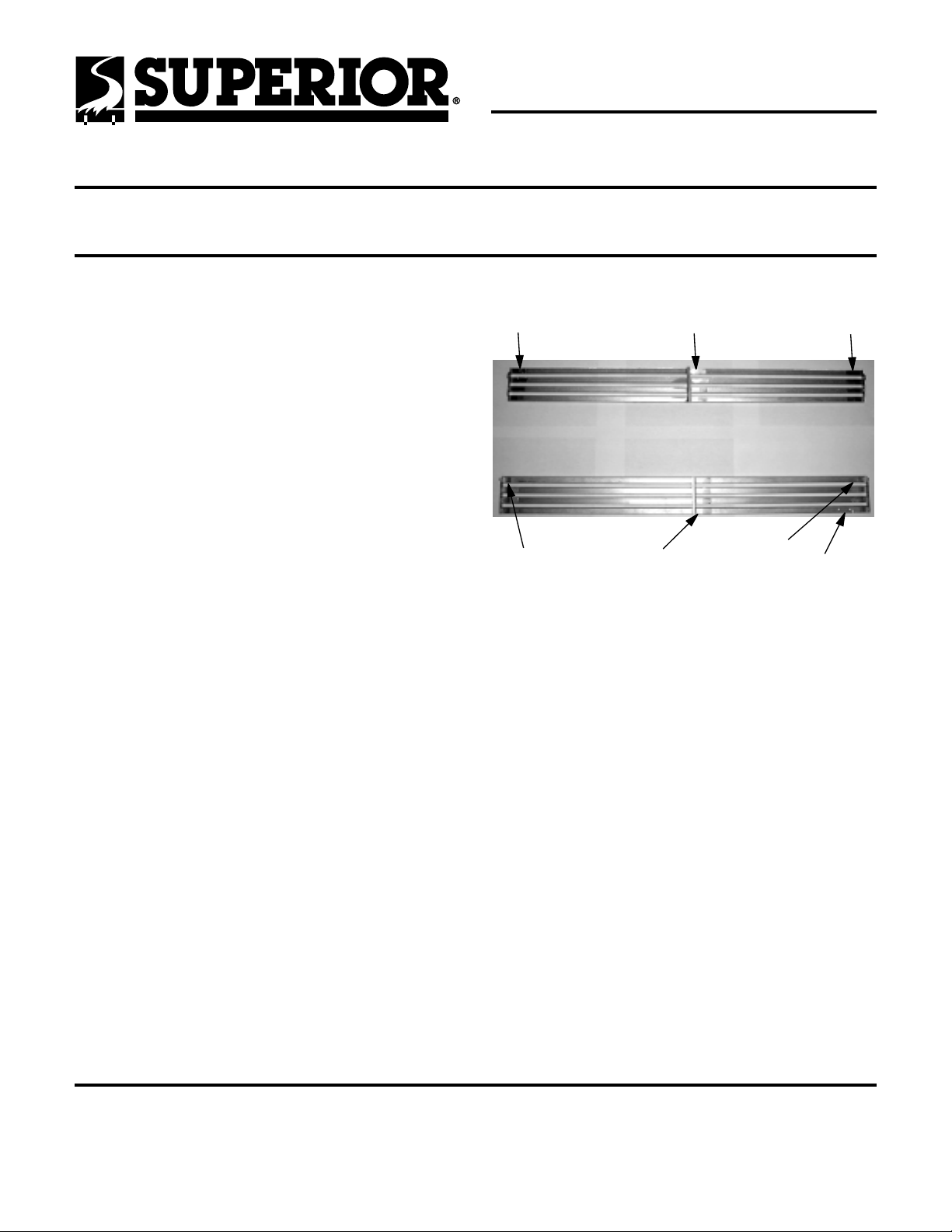
Step 4. Working with one assembly at a time, remove the existing
black louvers separating the brackets from the assemblies (
Figure 1
screwdriver and mallet to "tap" down the bend in each bracket
finger (restore the bend by hand before reassembly). Replace the
black louvers with the brass or brushed stainless louvers (without
the pre-drilled holes) using the existing brackets.
). To ease the removal of the brackets, use a side bladed
see
Existing
Bracket
Existing
Bracket
Figure 1
Center Bracket
(For No.’s H1526 thru
H1529 Only)
Top Louver Assembly
Bottom Louver Assembly
Center Bracket
(For No.’s H1526 thru
H1529 Only)
Existing
Bracket
Existing
Bracket
Louver
(With Pre-Drilled
Holes)
Step 5. Repeat Step 4 for the bottom louver assembly. Make sure
to replace the pre-drilled black louver with the pre-drilled brass or
brushed stainless louver.
Step 6. Remove logo from existing bottom louver with pre-drilled
holes and then snap the logo into the brass or brushed stainless
louver with pre-drilled holes.
Step 7. Reinstall the louver assemblies, reusing the existing screws
to reinstall the bottom assembly.
NOTE: DIAGRAMS & ILLUSTRATIONS NOT TO SCALE.
The manufacturer reserves the right to make changes at any time, without notice, in design, materials, specifications, prices and also to discontinue colors, styles and products.
Consult your local distributor for fireplace code information.
Printed in U.S.A. © 2004 by LHP
P/N 750,166M REV. B 07/2006
LHP
1110 West Taft Avenue
Orange, CA 92865
 Loading...