

Superior GRD-5000N, GHC-5000N, GRD-5000L, GHC-5000L Installation And Operating Instructions Manual
Page 1
"INSTALLER.THESE
INSTRUCTIONSMUSTBE
CONVEYEDTOHOMEOWNER"
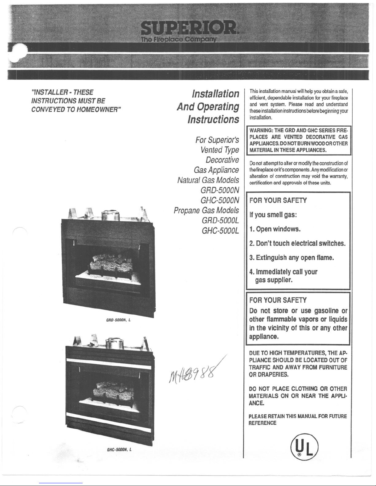
GHC-5000N.L
Installation
AndOperating
Instructions
ForSuperior's
VentedType
Decorative
GasAppliance
NaturalGasModels
GRD-5000N
GHC-5000N
PropaneGasModels
GRD-5000L
GHC-5000L
!r({J89y(
@
ThisinstaDationmanualwillhelpyouobtainasale,
efficient,dependableinstallationforyourfireplace
andventsystem.Pleasereadandunderstand
theseinstallationinstructionsbeforebeginningyour
installation.
WARNING:THEGRDAND GHCSERIESFIRE.
PLACES ARE VENTED DECORATIVEGAS
APPLIANCES.DONOTBURNWOODOROTHER
MATERIALIN THESEAPPLIANCES.
Do not attempt to after or modify the construction of
thefll'eplace or it'scomponents. Any modification or
alterationof constructionmay void the warranty,
certification and approvals of these units.
FORYOURSAFETY
Ifyou smell gas:
1.Open windows.
2. Don't touch electrical switches.
3. Extinguish any open flame.
4.Immediately call your
gas supplier.
FOR
YOUR SAFETY
Do not store or use gasoline or
other flammable vapors or liquids
in the vicinity of this or any other
appliance.
DUETOHIGHTE
ES,THEAp.
PUANCESHOUl rEDOUTOF
TRAFFICANDA1
FURNITURE
ORDRAPERIES.
DONOTPLACE OROTHER
MATERIALSON
THEAPPU.
ANCE.
PLEASERETAINTI
FORFUTURE
REFERENCE
Page 2
~
GENERALINFORMATION
Thisappliance compUeswithNational SafelyStan-
dards and is tested and listed by Underwriters
Laboratories, Inc. to ANSI Z21.50-1986 as a vented
decorative gas appliance.
Installation must conform to local codes. In the
absence of local codes installation must conform
with the current National Fuel Gas Code, ANSI
Z223.1. Theappliance,when installed,must be
electricallygroundedinaccordance withlocalcodes,
withthe National ElectricalCode, ANSIINFPANo.
70-1984.
Note:Installationandrepairshouldbe donebya
qualifiedserviceperson.Theapplianceshouldbe
inspectedannually
byaprofessionalserviceper-
son.Morefrequentinspectionslc/eaningsmaybe
requireddw toexcessive/intfromcarpeting,bed-
dingmaterial,etc.Itisimperativethatthecontrol
compartment,burnersandcirculatingairpassage
waysoftheappliancebekeptclean.
Provide for adequate ventilation.
~
Provide adequate clearances around air openings
and adequate accessibility dearance for service
and proper operation. Never obstruct the front
opening ofthe fireplace.
Minimumclearances to combustibles are:
Sides 112', Floor 0', Back 112', Ceiling 41 112',
Sidewall O', Vent Surfaces 1'.
Minimum inlet gas pressure is 4.5 inches water
columnfornatural gas and 11 inches water column
propane forthe purpose of input adjustment.
Maximuminlet gas supply pressure is 7.0 inches
water columnfornatural gas and 13.0 inches water
column for propane.
Input is 18,000 aTUMR
A 1/8' N.P.T. plugged tapping is provided on the
gas control along side of the outlet to the main
burner fora test gage connection.
This apptiance must oot be connected to a chimney
flue servicing a solid fuel burning appliance.
The appliance must be isolated from the gas supply
piping system by dosing its individual manual shut-
off valve during any pressure testing of the gas
supply piping system altest pressures equal to or
more than 112 psig.
2
INTRODUCTION
The GHC-SOOOis a heat circulating system that
utilizing a miUivok gas control valve and a piezo
ignition system. Glass doors, trim kits and a forced
air fan assembly are optional equipment.
The GRD-SOOO
is a radiantheat system that utiliz-
ing a millivoh gas control valve and a piezo ignition
system. Glass doors are optional equ~ment.
ASSEMBLYSTEPS
1.Position appliance prior to framing or into pre-
pared framing.
2.Route gas line to firebox compartment and install
m~livoh waD switch.
3. Install vent system.
4. Field wire main power supply to appliance junc-
tion box (only if optional fan assembly is to be
installed aI a later time).
5. Complete finished wall malerial and trim.
6. Install controls and burner assembly. Connect to
gas supply.
7. Wife remote millivolt wall switch to control valve.
8. Attach horizontal louvers andlor optional \rim
pieces.
9. Install the optional glass doors.
INSTALLATION
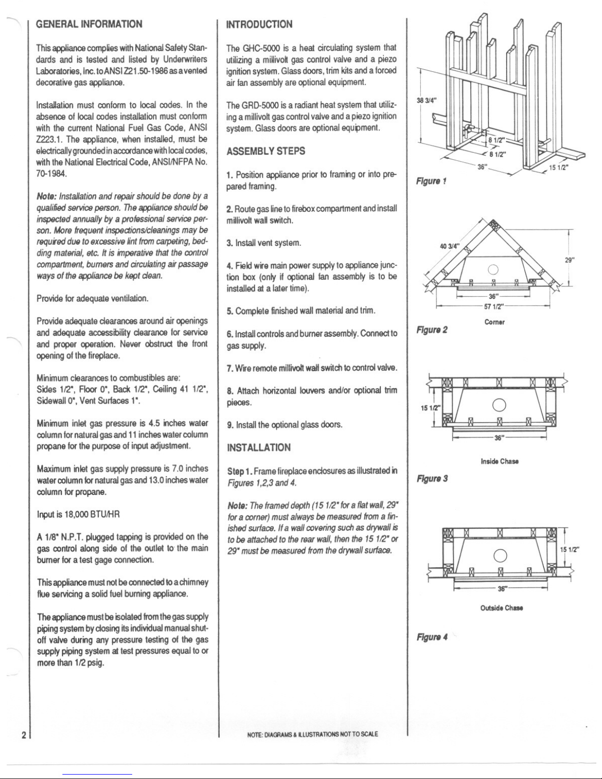
Step1. Frame fireplace endosures as illustrated in
Rgures1,2,3and4.
Note:Theframeddepth(15112"for8flatwall,29"
for8corner)mustalwaysbemeasuredfromafin-
ishedsurface.Ifa wallcoveringsuch
as drywallis
tobeattachedtotherearwall,thenthe15112"or
29"mustbemeasuredfromthedrywallsurface.
NOTE:DIAGRAMS& illUSTRATIONS NOTTO SCAlE
~
r
29"
i
~
Comer
FIgure2
36"
Inside Chase
FIgure 3
mt
36" I
Outside Chase
FIgure4
Page 3
~
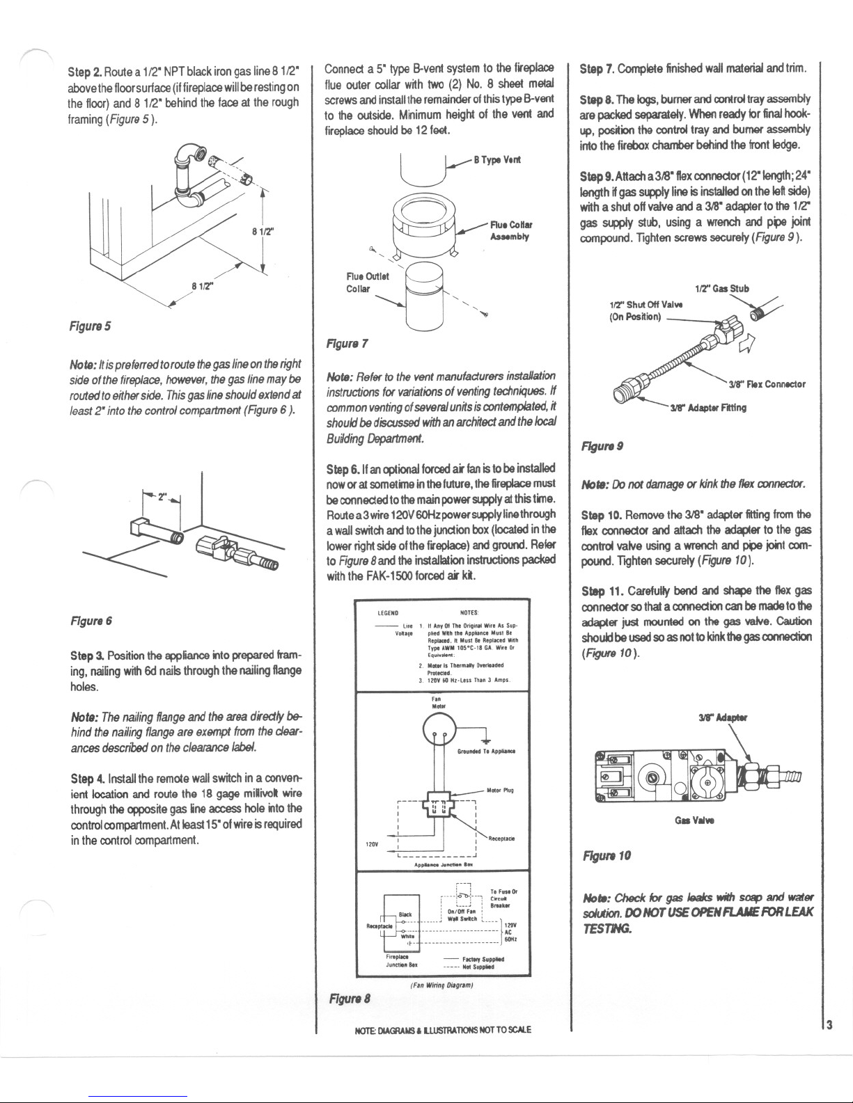
Step2.Routea112"NPTbiackirongasline8112"
abovethefloorsurface(iffireplacewillberestingon
thefloor)and8112"behindthefaceattherough
framing(Figure5).
~81fl'
Figure5
Note:Itisprefe"edtoroutethegaslineontheright
sideofthefireplace,however,thegaslinemaybe
routedtoeitherside.Thisgaslineshouldextendat
least2"intothecontrolcompartment(FIgure6).
~
jX'J
L
~~
FIgure6
Step3.Positiontheapplianceintopreparedfram-
ing,naifingwith6dnailsthroughthenailingftange
holes.
Not,:Thenailingflangeandtheareadirectlybe-
hindthenailingflangeareex9l1lptfromtheclear-
ancesdescn'bedontheclearancelabel.
Step4.Installtheremotewallswitchinaconven-
ientlocationandroutethe18gagemilivotwire
throughtheoppositegaslineaccessholeintothe
controlcompartment.Atleast15"ofwireisrequired
inthecontrolcompartment.
Connecta 5"typeB-ventsystemtothefireplace
flueoutercoUarwithtwo(2)No.8 sheetmetal
screwsandinstalltheremainderofthistypeB-vent
to theoutside.Minimumheightof theventand
fireplaceshouldbe12feel.
LYBTYpe Vlnt
8-.
FlulCo"ar
Assembly
" .
FlUIOIII
11
II""
Collar "
"
".."
FIgure
7
Note:RefertotheventmanufacturersinstaHation
instructionsforvariationsofventingtechniques.If
commonventingofseveralunitsiscontemplated,it
shouldbediscussedwithanarchitectandthelocal
BuildingDepartment.
Step6.11anoptionalforcedairfanistobeinstalled
noworatsometimeinthefuture,thefireplacemust
beconnectedtothemainpowersupplyatthistime.
Routea3wire120V OOHzpowersupplylinethrough
awallswitchandtothejunctionbox(locatedinthe
lowerrightsideofthefU'epIace)andground.Refer
toFIgure8andtheinstallationinstructionspacked
withtheFAK-1500forcedai' ki.
LEGEND NDTES,
Step7.Completefinishedwallmaterialandtrim.
Step8.Thelogs,burnerandcontroltrayassembly
arepackedseparately.Whenreadyforfinalhook-
up,positionthecontroltrayandburnerassembly
intothefireboxchamberbehindthefrontledge.
Step9.Attacha318"flexconnector(12"length;24"
lengthifgassupplylineisinstalledonthe leftside)
witha shutoff valve and a 318"adapter to the 112"
gassupplystub,usinga wrenchandp~ joint
compound.TIghtenscrewssecurely(Figure9).
112"ShutOffValve
(OnPos~ion)
FIgure 9
Note:Donotdamageor kinktheflexconnector.
Step 10. Removethe 318"adapter fittingfromthe
flex connectorand attachthe adapterto the gas
controlvalveusinga wrenchand ~ jointcom-
pound. Tighten securely(Figure10).
Step 11. Carefullybend and shape theflexgas
connector so that a connection can be madetothe
adapterjustmountedonthegasvalve.Caution
shouki be used so as not to kinkthegas connection
(FtgUf8 10).
W' Adlpllr
G. VII.
FIgure10
No,.: Check lor gas leaks with SOIipand water
soWon.DONOTUSEOPENFLAMEFORLEAK
TESTING.
3
- U.. 1 "A', 01Th.D", W", A. S",.
, ,"d WIh." A.."", M."..
"_d.hM."..'ep',,"Whh
T,peAWMIOS.C A we. D'
E,."...",.
2 M ,. Th..mOlyD d"
""'_d.
,. 12DY" N..lou Th" , Am,..
",
M""
M""~,,
12DY
~---
,
I
,
I
~ Ii""""'"
l ~
A" , ...
~
cnnl~';:L T"'.....
,: :,Ce,..
BIle, :D';Oti-:."i."""
-- --- hm.J WoO"",Lnu
~f -~~~~:::::---~~~:::::::}:r.
FI..-
"'d." ... - 'oc:1WyS......
no-. ... S...",
(F.n WiringO;.g""'1
FIgure8
NOTE:DlAGlAMS' LlUSTRAllONS NOT TO SCAlE
Page 4

r--
Aftergas lineinstallation iscomplete, use insulation
(not provided) to pack space where gas line pene-
trates the appliance. Pack insulation tightly from
outside the appliance tocompletely seal this space.
Step12.RemoteMIllivoltWallSwitchWiring.
Attach one wire !rom the remote miUivolt wall switch
to the "TH" terminal on the gas control valve.
Conned the otherwire from the remote millivok wall
swftch to "TH TP" terminal at the gas control valve
(Figure11).
r ~-
I
I
I
I
I
I
I
I
I
I
I
I
I
I
,
;:~
,
-I -I
~::I:
II~
r~:mo~~tfj-+-[2
GasVllve
To Remote Mllivol
Wall SwItch
Rgure11
CAUTION:DO NOT WIRE REMOTEWALL
r'~, SWITCHTOAMAINPOWERSUPPLY.
Figure12
Figure13
4
HROIZONTALTRIMINSTALLATION
On the GHC Model, remove the four (4) black
louvers and the two (2) antique brass cover pieces
from the protective container and fasten onto the
face ofthe fireplace. The louver str~ snap onto the
louver pegs wnhoutthe need fortools. T 0 assemble
the louver str.,s, tilt the str., on top of the pegs and
snap lower edge to lock in place. The antique brass
cover pieces are mounted over the support bars
directly over and below the fireplace opening. They
also snap into place. Keep the locking dimples on
the bottom side of the covers when installing.
FLAMECOLORIZATIONDEVICES
The burner assembly is equ.,ped with a special
flame enhancement rod located between the lower
logs and a mineral fiber llame enhancement strip
across from the (lower) burnerparts. These devices
colorize the gas flame and produce the "ember
effect".
In normal operation, these devices will provide
many hours ofsatisfadory performance. Overtime,
the orange color wUldiminish in intensity and it will
be necessary to purchase a replacement rod and/
or mineral fiber flame enhancement device. These
devices are available at nominal charge from your
local distributor/dealer or directly form Superior.
Flam. Enh8nctm.nt Rod
LogSet
Against
Back
Waft
HIGHELEVATIONDERATING
Wheninstallingthesefireplacesabove4,000feel
level, n is recommended that the fireplace bumerbe
derated by changing the existing orifice to a smaller
one. Order and install appropriate high altnude
orificekit(Figure15). .
i
~,j
1...,
~
148 Natural
158 Propane
(UseWhen
DeratingBurner)
Rgure15
ACCESSORIES
OptionalFanKIt
If the optional Ian kit, Model FAK-1500 is to be
installed on the GHC-SOOONor GHC-SOOOLgas
fireplace,refertotheinstallaiton instrudions packed
wnh the fan assembly.
The GHC-5000NandGHC-
SOOOLgas fireplacehas beenprewiredat the fac-
tory to accept the forced air kit at some later time.
The firepalce,must, however, be connected to
main
powersupplyattime of installation ifthe FAK-
1500 forced air kit is to be instaUedlater.
HorizontalTrimInstallation
There are three optional horizontal trim kits, Models
35HTK-SPS, HTK-PB and HTK-AB and two 0p-
tional vertical trim kits, Models VTK-ABR and VTK-
GOEavailableforusew~htheGHC-SOOOgas
fireplace.Refertothespecificinstallationinstruc-
tionspackedwnh eachtrimkitlortheirproper
usage.
OptionalGlassDoors
Several models of optional glass doors are avail-
able for installation on these gas fireplaces. Use
glass door Models 35G-PB, 33BF-AB, 33GOD-AS,
33GBF-PB, 33GBF-SPB, 33GBFT-SPB, 33GBF-
ABR and 35GT-SPS wnh Model GHC-SOOON,L.
ForModelGRD-SOOON,L gasfireplaces,useglass
door Models 33R-PB, 33BF-AB, 33GOD-AB,
33GBF-SPB, 33GBFT-SPB, 33GBF-ABR
and
33GBF-PB. Refer to the specific installation in-
structions packed w~h each glass door assembly
for installation
details.
Figure14
COLDCLIMATEINSULATION
If you live in a cold climate, seal all cracks around
your fireplace with non-combustible material and
wherever cold air could enter the room. It is espe-
cially importantto insulateoutside chase cav~y
between studs and under floor on which rests, if
floor is above ground level.
Surround material must be caulked where nmeets
the black metal facing of the fireplace to avoid
air
intrusion. Use non-combustible caulking material
onlyonfireplacefacingtoseal.
Do nol place insulation materials in the 1"gas vent
system clearance space.
NOTE:DIAGRAMS&LlUSTRA11ONSNOTTOSCALE
Page 5

~
GLASSDOOROPERATINGPRECAUTIONSAND
INSTRUCTIONS
.Keep wire mesh screens closed during fireplace
use.
.Never clean glass when doors are hot. Avoid over-
spray of cleaner on brass pieces.
.Glass and metal frames get hot. Use only the
wooden handles to open and close doors.
CAUTION:THEFIREPLACESHOULDONLYBE
OPERATEDWITHTHEGLASS DOORSFULLY
OPENORFULLY CLOSED.
-$-
Figure16
Bi.Fold
Glass Doors
-$-
~-T"~"'-"'--
1 ' '---'
AIl-Glassl'M'And Twin-Pan.
GlassDoors
Figure17
FIREPLACESPECIFICATIONSGHC.5000N,L
~
273/4"
~
357~'
!
41/4"
~
I
I
Top
Figure18
331/4"
I
341'rt'
U
I
21"
I
1112"
-'-~
.-
Rgure19
PJ
-i !-
~
4F~_.
8E . ilt D' ~12"
L
7~~
i
10" I
'6"~lilrt,T ~16"-.J
Ilrt'
Left Right
Rgure20
Front
FIREPLACESPECIFICATIONSGRD-SOOON,L
6112"
l;
L
Figure 22
357~'
331/4"-
.-
I
I
,
I
38314"
!
lkP'f
~15,,-J
Right
5
2'"
I
Front
Left
Rgur.23
NOTE:DIAGRAMS& IlLUSTRAnoNS NOTTOSCAlE
Page 6

~
FINISHEDWALLDETAILS
" isbesttoframeyourfireplaceafter~ispositioned.
Framewith2 x 4'sorheavierlumber.Framein
accordancew~hlocalprevailingbuildingcodes.
Note: Theheadermayrestonthetopmetalspac-
ersbut mustnot benotchedtofitaroundthem.
Toinstallthefireplacelacingflushwiththefinished
wallpos~ionframeworktoaccommodatethethick-
ness01thelinishedwall(Figure24,AandB).
Surroundmaterialscanbeplacedaroundthelire-
placefacingtoprovideaflushsurfacebetweenthe
surroundmaterialsandthefireplacelacing(Figure
24, C and0 ).
FinishedWill
~~,
/
11" Mln. ,
LL
GHC-5000N,L
It.
GRD-5000N,L
Non-combulllbl,
B
W8I1CoV8ring
finished Will
""Min. '
LL
GHC-5000N,L
C
FIgure 24
GRD-5000N,L
Non-combustlbl, D
WallCovering
Itisnotnecessarytoinstallahearthextensionw~h
thisgasappliance."a hearthextensionisused,do
notblockthelowerlouveredareaoftheGHC-5OOO.
Anyhearthextensionusedislorappearanceonly
andneednotconformtonormalspecifications.
Acombustiblemantelshellprojectingamaximum
018' Iromthewallmaybeinstalleda minimum
distance0111'abovethe GHC-5OOOandGRD-
5000fireplaceopening(Figure25).
6
GRD-5000 Or GHC-5000
Figure25
OPERATION
Tooperatetheappliance,relertothelightingin-
structionslocatedontheback01theIrontcover
assembly.
Yourappliancecontrolsystemisamillivotttype.It
consists01a pilotbumer,piezoign~ion,a gas
controlvalveandanONIOFFsw~ch.
Toobtainproperoperation,~isimperativethaithe
pilotandmainbumerflamecharacteristicsare
steady,notliltingorfloating,andbeblueincolor
(Figure
26 ).
Note:Forpropaneuse,airshuttermustbeopen
1/4inch(Figure30).
Naturel Of Porpana G.. Burntr
FIgure 26
Approximatelythetop3/8'atthepilotgenerator
(thermopile)shouldbeengulfedinthepilotllame
(Figure27 ).
Pilot Gtn8f8lor
(TherlllOpile)
Piezo
Ignitor
Theairshuttersontheventuritubehavebeenset
attheproperpos~ionatthefactoryforbothnatural
andpropanegasunits.Theairshutterfornatural
gashasbeensetinafullopenposition(Figures28
and29).
ManKold
8~~.
VenturiTube
NaturelG..
FIgure28
AIrShutter
1l0~\~
I~
~~3J'8"
Naturel Gas Top View
Figure29
Theairshutterforpropanehas
beensetinthehalf
open, or 1/4' opening(Figures30 and 31).
""'~ DO"
~
AirShutt'r
/ J~~ ..-
Venturi Tube
Propane Gas
Figure30
~
lJ t:.
POrpBne Gas Top VieW
Figure31
Figure27
7J
NOTE:DIAGRAMS&IlLUS1RATIONSNOTTOSCAlE
Page 7

,, ,
\
Anyvariationattheseairshuttersmayresultinan
erraticflameand/orthepossibilityofsooting,distin-
guishedbyabrightyellowflame.Anyadjustments
totheairshutterdifferentfromthatdescribedabove
couldcausetheburnerassemblyto malfunction
andcouldvoidthewarranty.
OPERATIONGUIDELINESAND
MAINTENANCEINSTRUCTIONS
1. Uponcompletingyourgaslineconnection,a
smallamountofairwillbeinthelines.Whenfirst
lightingtheappliance,~willtakeafewminutesfor
thelinesto purgethemselvesof this air.Once
purgingiscomplete,thepilotandburnerwillfight
andoperateasindicatedintheinstructionmanual.
Subsequentlightingsoftheappliancewillnotre-
quiresuchpurging.
2.When~tforthefirsttime,theappfiancewiDem~
aslightodorforanhourortwo.Thisisduetothe
"curing"ofthelogsand"burn-offofinternalpaints
andlubricantsusedinthemanufacturingprocess.
3. Keepcontrolcompartment,logs,burnersand
areasurroundingthelogscleanbyvacuumingor
brushingatleasttwiceayear.Donotvacuumthe
/"- mineralwoollocatedin the frontof theburner
assembly.
CAUTION:THE LOGSCAN GET VERYHOT-
HANDLEONLYWHENLOGSARECOOL
4.Alwaysturnoff gasto pilotbelorecleaning.
Beforere-lighting,refertothelightinginstructions.
5.Theapplianceandventingsystemshouldbe
inspectedbeforeuseor at leastannuallyby a
qualifiedserviceperson.
6.Alwayskeeptheapplianceareadearandfree
fromcombustiblematerials,gasolineandother
flammableliquids.
7.Neverobstructtheflowofventilationair.Keepthe
frontoftheappliancedearofallobstadesand
materials.
WARNING:CHILDRENANDADULTSSHOULD
BE ALERTED TO THE HAZARDS OF HIGH
SURFACETEMPERATUREANDSHOULDSTAY
AWAYTO AVOIDBURNSOR CLOTHINGIGNI.
TION.YOUNGCHILDRENSHOULDBESUPER-
VISEDWHENTHEY AREINTHESAMEROOM
~ . ASTHEAPPUANCE.
MAINTENANCE
IMPORTANT:Turnoffgasandelectricalpower
beforeservicingappliance.Itisrecommendedthat
acompetentservicemanperformthesecheckups
atthebeginningofeachheatingseason.
In orderto properlycleantheburnerandpilot
assembly,removetheglassenclosure,thelogs
andexposetheburnerandpilotassembly.
CleaningBurnerAnd
Pilot
Cleanallforeignmaterialsfromtopofburnerand
frombottompanelbelowburner.Checkto make
surethatburnerorificeisclean.
Visuallyinspectpilot.Brushorblowawayanydust
or lint accumulations.If pilotorificeisplugged,
disassemblymayberequiredtoremoveanyfor-
eignmaterialfromorificeortubing.Whenappliance
isputbackinservice,checkpilotflamepatterns
w~hRgure27.
WARRANTY
Yourgasfireplaceiscoveredbyaoneyearlimned
warranty.Youwitlfindacopyofthewarrantyinthis
manual.Pleasereadthewarrantytobefamifiarwnh
n'svaluablecoverageandfileRwRhothersyou
saveforfuturereference.
MILLIVOLTCONTROLLIGHTING
INSTRUCTIONS
1.Turnremotewalls~ch to"Off".Tumgasvalve
knobto"pilor,depressandturnto"011".Waitfive
minutes.
2.Turngasvalveknobto"pilot".
3.HoldindepressedposRionandlightpilotby
triggeringthesparkign~er(pushingredbutton)until
pilotlights.Continueholdingknobdepressedfor
approximately1112minutesuntilpilotremainsIn
whenknobisreleased.
4.Turngasvalveknobto"an".Tumremoteswnch
to"On".Burnerwincomeon.
SHUTDOWNINSTRUCTIONS
1.Theburnermaybeturnedoffbyturningremote
sw~ch"Off".ThepilotwillremainInfor returnto
normalservice.
2. Forcompleteshutdown:Tumremotesw~ch
.olr. Depressandturngasvalveknooto"Off'.
NO~:DIAGRAMS&illUSTRATIONSNOTTOSCAlE
PILOTBURNERADJUSTMENTS
1.Removepilot adjustmentcaponmainvalve.
2.Adjustpilotscrewtoprovideproperlysizedflame
(Figure27).
3.Replacepilotadjustmentscrew.
TROUBLESHOOTING
WrthproperinstaJlationandmaintenance,yournew
gasfireplaceshouldprovideyearsoftroublefree
service.Ifyoudoexperiencea problem,trouble
shootingguidesareprovidedinthismanual.These
guideswillassistyouoraqualifiedserviceperson
inthediagnosisof problemsandthecorrective
actiontobetaken.
REPLACEMENTPARTS
Contactthefactoryforquestionsconcerningprices
andpoliciescoveringreplacementparts.Partswill
besh"pedatprevailingprices.Normally,allparts
canbeorderedthroughyourSuperiordistributoror
dealer.
Whenorderingrepairparts,alwaysgivethefollow-
inginformation:
1.Themodelnumberoftheappliance
2.Thepartnumber
3.Thedesaiptionofthepart.
4.Theinstallationdateoftheappliance.
Ifyouhaveanyquestionsorproblems,contactyour
localdistributorldealeror:
Superior FIreplace Company
4325ArteslaAvenue
FuHerton,CA 92633
(714) 521-7302
7
Page 8

REPLACEMENTPARTSLIST
.~
ROBERTSHAWCONTROLS
8
*Note:Item21intendedforhighaltitudeinstallation.Item23includesitems14and22inasinglekit.
GHC.SOOON GRD.SOOON
GHC.SOOOL
GRD.SOOOL
NO.
DESCRIPTION
PARTNO. CTY
PARTNO. CTY
1
GasFireplaceAssembly
024711
1
024712
1
2
Bar,Louver
024501
4
-
3
Bar,Top
024491
1
-
4
Trim,Upper/Lower
024151 2
-
5
Panel,Screen/Pull
090083
2
090083
2
6
Rod,Screen
011381
2 011381
2
7
Refractory,Bottom
024931
1 024931
1
8
FrontCoverAssy.
025831
1 025833
1
9
Log,Main
028121
1 028121 1
10
Log,TopRight
028141
1 028141 1
11
Log
,TopLeft
028151
1 028151 1
12
Cover,ScreenRod
011351
1
011351
1
13 WallSwitchKit
025971
1
025971
1
14
FrontFlameEnhancementStrip
032631
1
032631
1
22
FlameColorizationRod
032351
1
032351
1
*23 FlameEnhancementKit
033711
1
033711
1
GHC.SOOON GHC.SOOOL
GRD.SOOON GRD.SOOOL
NO. CONTROLDESCRIPTION
PARTNO. CTY
PARTNO.
CTY
15
Valve,GasControl(#7000MVRLC)
009737 1 093771
1
16
Orifice,#46(natural),#56(propane)
092751
1 092752 1
17
Igniter,Mini
091301
1 091301 1
18
PilotGenerator(Thermopile-TP-75)
094699
1 094699 1
19
PilotAssembly
093761
1
093762
1
20
BurnerAssembly
024981
1 024981 1
*21
HighAltitudeOrificeKit
027961
1
027962
1
Page 9

c._.
iI.
°1 ~
00
13
NOTE:DIAGRAMS&ilLUSTRATIONSNOTTOSCAlE
~
GHC-5000N,L
0
GRD-5000N,L
9
Page 10

~
TROUBLESHOOTINGTHEELECTRICPIEZOIGNITOR
ANDGASCONTROLSYSTEM
MODELSGHC-5000N,GHC-5000L,GRD-5000N,GRD-5000L
Note:Beforetroubleshootingtheeleetriepiezoignitorsystem,besureexternalgasshutoffvalve,locatedatthegassupplyinlet,isinthe"ON"position.
~
10
NOTE:DIAGRAMS&ilLUSTRATIONSNOTTOSCAlE
SYMPTOM
POSSIBLECAUSES
CORRECTIVEACTION
1.Sparkignor willnotlightpilotafter
A.Defectiveignor 1.Checkforsparkatelectrodeandpilot;ifnospark
repeatedtriggeringofredbutton.
(nosparkatelectrode). andelectrodewireisproperlyconnected,replace
theignor.
B.Defectiveormisalignedelectrodeatpilot
1.Usinga match,lightpilot.Ifpilotlights,tumoff
(Sparkatelectrode). pilotandtriggertheredbuttonagain.Ifpilotlightsan
impropergasmixturecausedthebadlightinganda
longerpurgeperiodisrecommended.Ifpilotwillnot
light-checkgapatelectrodeandpilot
-shouldbe
1/8inchtohaveastrongspark.IfOK,replacepilot
assembly(Figure27).
2.PilotwillnotstayI aftercarefullyfollowing
A.Defectivepilotgenerator(thermopile)or
1.Checkpilotflame.1tmustimpingeonpilotgen-
lightinginstructions.
remotewallswitchwiring. erator(Figure27). Cleanand/oradjustpilotfor
maximumflameimpingementongenerator.
2.Besurewireconnectionsfromgeneratoratgas
valveterminalsaretightandgeneratoris fully
insertedintopitotbracket.
3.Oneofthewallswitchwiresmaybegrounded.
Removewallsch wiresfromvalveterminals.If
pilotnowstaysm,tracewallswch wiresfora
ground.Maybegroundedtofumaceorgassupply.
4.Checkpilotgeneratorwh miltivohmeter.Take
readingatgeneratorterminalsofgasvalve.Should
read325miltivoltsminimumwhileholdingvalve
knobdepressedin pilotposion andwallswitch
"OFF".Replacefauhygeneratorifreadingisbelow
specifiedminimum.
B.Defectiveautomaticvalveoperator. 1.Turnknobto"ON",placewallswitchto "ON"
mlivoltmetershouldreadgreaterthan100MV.If
thereadingisOKandtheburnerdoesnotcomeon,
replacethegasvalve.
3.Pot burning,nogastoburJlftr,valveknob
A.Wallswitchorwiresdefective.
1.Checkwallswitchandwiresforproperconnec-
"ON",wallswitch"ON". tions.Jumpwiresforproperconnections.Place
jumperwireacrossterminalsat wallsch. If
burnercomeson,replacedefectivewaDswitch.If
OK,placejumperwiresacrosswallsch wiresat
gasvalve.Ifburnercomeson,wires
aredefective
orconnectionsarebad.
B.Pot generatormaynotbegenerating
1.Re-checkSymptom#2.
sufficientmivohage.
C.Pluggedburnerorifice. 1.Checkburnerorificeforblockag9andremove.
4.Frequentpilotoutageproblem.
A.Pilotflamemaybetooloworblowing(high) 1.Clean/adjustpilotflametormaximumflame
causingthepilotsafetyto dropout.
impingementonpilotgenerator(FIgUf927).
 Loading...