

Superior DS-36RN, DS-36RP, DSR-HTK, ELB-45, DSR-EXT12 Installation And Operating Instructions Manual
...Page 1
Installation
And Operating
Instructions
For Superior's
Discovety Series
Sealed Combustion
WARNING: IMPROPER
INSTALLATION
ADJUSTMENT,
ALTERATION,
SERVICI
OR
MAINTENANCE
CAN
CAUSE
INJURY
OR
PROPERTY
DAMAGE. REFER
TO
THIS
MANUAL.
FOR
ASSISTANCE
OR
AODI.
TIONALINFORMATION
CONSULTAIIUALI-
FIE0
INSTALLER,
SERVICE
AGENCY
OR
THE
GAS
SUPPLIER.
FOR YOUR
SAFETY
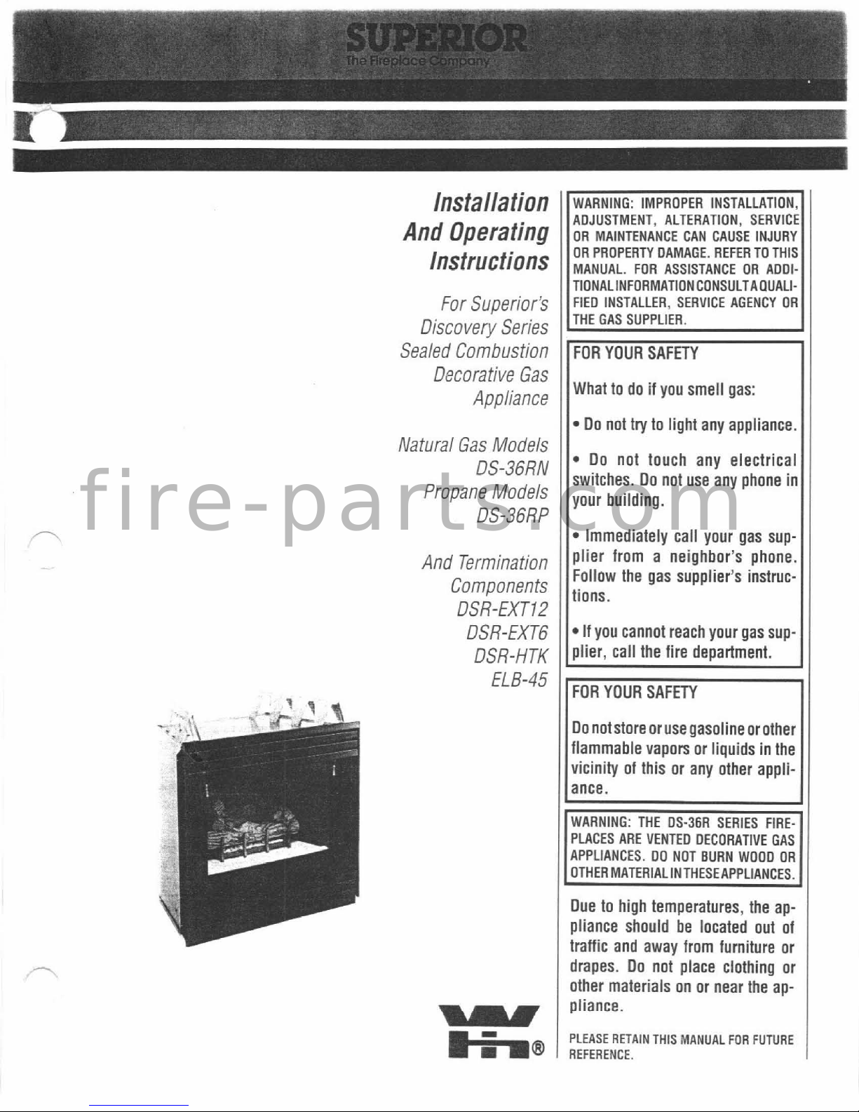
Natural Gas Models
DS-36RN
Propane Models
DS-36RP
Decorative Gas
Appliance
And Termination
Components
DSR-EXT12
DSR-EXT6
DSR-HTK
EL
B-45
What to do if you smell gas:
11-
Do not try to light any appliance.
I
Do not touch any electrical
switches. Do not use any phone in
your building.
Immediately call your gas supplier from a neighbor's phone.
Follow the gas supplier's instruc-
tions.
If you cannot reach your gas sup-
plier, call the fire department.
Do notstoreoruse gasoline
orother
flammable vapors or liquids in the
vicinity of this or any other appliance.
PLACES
ARE
VENTED
DECORATIVE
GAS
APPLIANCES.
DO
NOT
BURN
WOOD
OR
Due to high temperatures, the appliance should be located out of
traffic and away from furniture or
drapes. Do not place clothing or
other materials on or near the appliance.
I
PLEASE
RETAIN
THlS MANUAL
FOR
FUTURE
REFERENCE.
I
f i r e - p a r t s . c o m
Page 2
I
TABLE
0,F
CONTENTS
-
......................................
lntroduct~on page
2
.........................
General information page 2
Location and clearances
..................
page
3
Installation
.....................................
a
3
Framing dimensions
........................
page 3
......................
Appliance dimensions page
5
..................
Outside wall termination page 6
Gas connections
...........................
-...page
8
....................
High elevation derating page
8
....................
Finishing requirements page 10
......................................
Accessories page
11
...........................
Operation and care page 11
Maintenance age 11
Partslcomponents
..........................
page 12
Troubleshooting guide
.....................
page 13
Replacement parts list
.....................
page 14
.......................
Liahtino instructions paqe 16
. .
Warranty.
-I
I
TYPICAL
INSTALLATION
This installation manual will help you obtain a
safe,
efficient,
dependable installation for your
fireplace and vent system. Please read and
understand these installation instructions before beginning your installation.
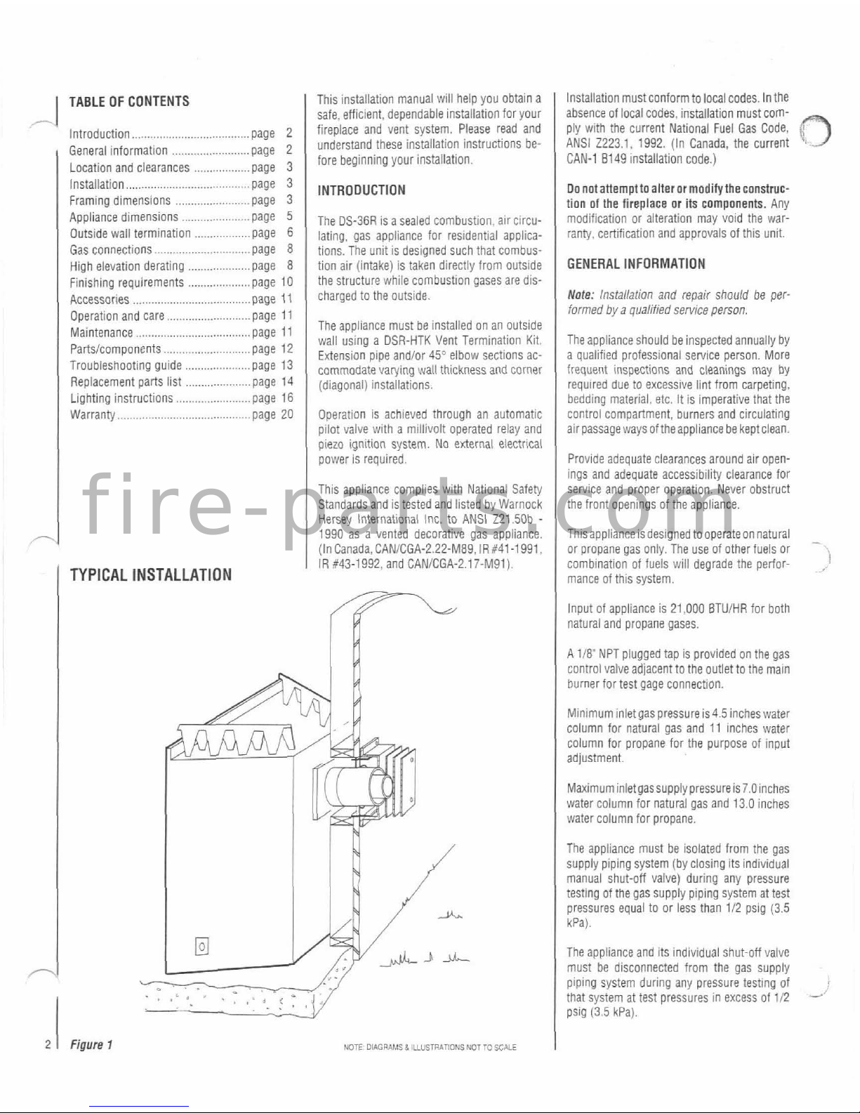
INTRODUCTION
The DS-36R is a sealed combustion,
alr circu-
lating, gas appliance for residential applica-
tions. The unit is designed such that combus-
tion air (intake) is taken directly from outside
the structure while combustion gases are discharged to the outside.
The appliance must be installed on an
outslde
wall using a DSR-HTK Vent Termination Kit.
Extension pipe
andlor 45Vlbow sections ac-
commodate varying wall thickness
and
corner
1
(diagonal) installations.
Operation is achieved through an automatic
pilot valve with a millivolt operated relay and
piezo ignition system. No external electrical
power is required.
This appliance complies with National Safety
Standards and is tested and listed by Warnock
Hersey International
lnc. to ANSI
Z21.50b
-
1990 as a vented decorative gas appliance.
(In
Canada,CAN/CGA-2.22-M89.lR:41-1991
IR 643-1992, and CANICGA-2.17-M91).
2
1
Figure
1
NOTE DiAcRAMs 8 UusrnArIoUs UoT
To
SCALE
Installation must conform to local codes. In the
absence of local codes, installation must comply with the current National Fuel Gas Code,
3
ANSI 2223.1. 1992. (In Canada, the current
CAN-1
8149 installation code.)
Donotanempttoalterormoditytheconstmc-
tion of the fireplace or its components. Any
modification or aiteration may void the warranty, certification and approvals of this unit.
GENERAL INFORMATION
Note:
Installation
and repair should be
per-
formed
by a qualified sennce person.
The appiiance should be inspected annually by
a oualified orofessionai service oerson. More
frequent
lnipections and cleanings may
by
required due to excessive lint from carpeting,
bedding
material. etc.
It
is imperative that the
control compartment, burners and circulating
air passage ways
oftheappllance be keptclean.
Provide adequate clearances around air openings and adequate accessibility clearance for
service and proper operation. Never obstruct
the front openings of the appliance.
Thlsappliance 1s deslgned tooperateon natural
-
or propane gas only The use of other fuels or
comb~nat~on of fuels
will
degrade the perfor-
.
mance of thls system
Input of appliance is 21,000
BTUiHR for both
natural and propane gases.
A 118' NPT plugged tap is provided on the gas
control valveadjacent to the outlet to the main
burner for test gage connection.
Mtn~mum inlet gas pressure is4.5 incheswater
column for natural gas and 11
Inches water
column for propane for the purpose of input
adjustment.
Maximum inletgassupply pressure
is7.Oinches
water column for natural gas and 13.0 inches
water column for propane.
The appliance must be isolated from the gas
supply
plping system (by closing its individual
manual shut-off valve) during any pressure
testing of the gas supply
piplng system at test
pressures equal to or less than 112 psig (3.5
kPa).
The appliance and its individual shut-off vaive
must be disconnected from the gas supply
piping system during any pressure testing of
that system at test pressures in excess of 112
-'
psig
(3.5
kPa).
f i r e - p a r t s . c o m
Page 3
Do not use this appliance if any part has been
-
under water, Immediately call a qualified service technician to inspect the appliance and to
replace any pans of the control system that
have been under water.
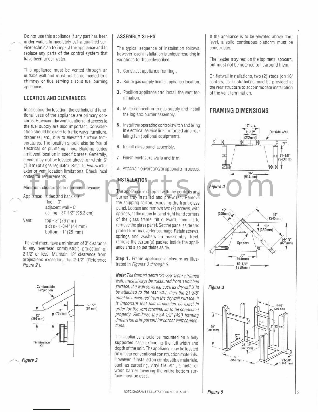
ASSEMBLY STEPS
The typical sequence of installation foilows.
however,each installation isunique resultingin
variations to those described.
This appliance must be vented through an
1.
Construct appliance framing
outside wall and must not be connected to a
If the appliance is to be elevated above floor
level, a soiid continuous platform must be
constructed.
chimney or flue
sewing a soiid fuel burning
appliance.
LOCATION AND CLEARANCES
The header may rest on the top metal spacers.
but must not be notched to fit around them.
2.
Routegas supply line toappliance location.
3.
Position appliance and install the vent termination.
On
flatwall installations. two (2) studs (on
16'
centers. as illustrated) should be provided at
the rear structure to accommodate installation
of the vent termination.
In selecting the location, the esthetic and
func-
4.
Make connection
gas Supply and install
FRAMING DIMENSIONS
tional uses of the aonliance are orimaw con-
the log and burner assembly.
,
.
,
~~
cerns. However, thevent location and access to
the fuel supply are also important. Consideration should be given to
traffic ways, furniture.
draperies, etc., due to elevated surface temperatures. The location should also be free of
electrical or plumbing lines. Building codes
limit vent location in specific areas. Generally,
a Vent may not be located above. or within
6'
(1.8 m) of a gas regulator. Refer to
FigureGfor
exterior vent location limitations. Check local
codes for requirements.
Minimum clearances lo combustibles are:
,-
Appliance sides and back - 0"
floor - 0"
adjacent wall - 0'
celiing - 37-112'
(95
3
cm)
Vent
top
-
3'
(76
mm)
sides
-
1-314"
(44
mm)
bottom
-
1'
(25
mm)
The vent must have a minimum
Of3"Clearance
to any overhead combustible projection of
2-112" or less. Maintain
12'
clearance from
projections exceeding the
2-112" (Reference
Figure 2
)
.
+-.
Figure
2
5.
Install theoperating controlswitchand bring
in electrical service line for forced air circulating fan (optional equipment).
6.
install giass panel assembly.
7.
Finish enclosure walls and trim.
8.
Anachairlouversandioroptionaltrimpieces.
INSTALLATION
The appliance is shlpped with the controis and
burner tray instailed and pre-wired. Remove
the shipping carton. exposing the front glass
panel. Loosen and remove two (2) screws. with
springs,atthe
upperieftandrighthandcorners
of the glass frame, tiit outward. then lilt to
removethe glass panel.
Setthe panel asideand
protectfrom inadvertentdamage. Retainscrews.
springs and washers for
reassembly. Next.
remove the
carton(s) packed inside the appii-
ance and also set these aside.
Step
1.
Frame appliance enclosure as illus-
trated in
Figures 3 through
5,
Note: The frameddeprh (21-3i8"froma framed
wall) mustalways be measured from a finished
surface. If a wall covering such as
drywall is to
be
attached to the rear wall, then the 21-3/8~
must be measured from the drywall surface. It
is important that this dimension be exact in
order far the vent
term~nal kit to be connected
properly.
Similarly. the 34-71.?
(491
framing
dimension is important forcorner
ventconnec-
t10ns.
The appliance should be mounted on a fully
supported base extending the full width and
depth
ofthe unit. Theappliance may be located
on or nearconventional construction materials.
However, if installed on combustible materials,
Such as carpeting, vinyl tile, etc.. a metal or
wood barrier covering the entire bottom sur-
face
must
be
used.
15.
O.C.
l%.,i?
m*
+
Outside
Wall
Figure
3
Figure
4
I
NOTE
OWGRAMSb
ILIU5TR*mONS
WTTO
SCALE
I
Figure
5
f i r e - p a r t s . c o m
Page 4
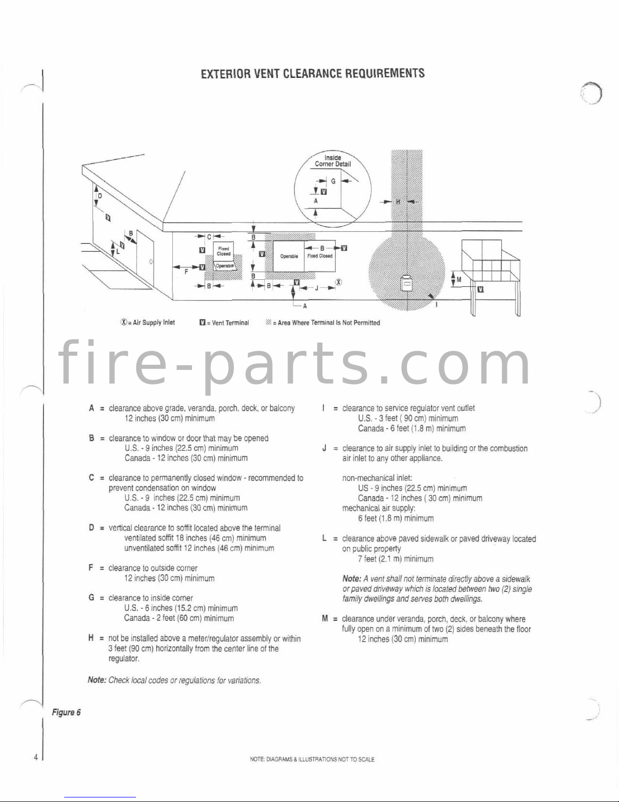
EXTERIOR VENT CLEARANCE REQUIREMENTS
a=
Air
Supply Inlet
Cl=
Vent
Terminal
A
r
Area
W)ma
Tminal Is
Not
Pennmed
I
A = clearance above grade, veranda, porch, deck, or balcony
12 inches (30 cm) minimum
B
=
clearance to window or door that may be opened
U.S.
-
9 inches
(22.5
cm) minimum
Canada
-
12 inches
(30
cm) minimum
C
=
clearance to permanently closed window - recommended to
prevent condensation on window
U.S.
-
9
inches (22.5 cm) minimum
Canada
-
12
inches (30 cm) m!nlmum
D
=
vertical ciearance to soffit located above the terminal
verlaled sorl
18
rcnes 146
CT)
ntnlmm
~nvent ate0
SOY
'2
ncpes
(46 cn, T n
~1-n
F
=
clearance to outside comer
12 inches (30
cm) minimum
G
=
clearance to inside comer
U.S.
-
6
inches (15.2 cm) minimum
Canada
-
2 feet
(60
cm) minimum
H
=
not be installed above a metedregulator assembly or within
3 feet (90 cm) horizontally from the center line of the
regulator.
I
Note:
Check
local codes or regulations for variations.
I
=
clearance to service regulator vent outlet
U.S.
-
3
feet ( 90 cm) minimum
Canada
-
6
feet (1.8 m) minimum
J
=
clearance to air supply inlet to building or Vle combustion
air inlet to any other appliance.
non-mechanical inlet:
US
-
9
inches (22.5 cm) minimum
Canada - 12 inches ( 30 cm) minimum
mechanical air supply:
6
feet (1.8 m) minimum
L
=
clearance above paved sidewalk or paved driveway located
on public
propeq
7
feet (2.1 m) minimum
Note:
A
vent shall
not
terminate directly above a sidewalk
or paved dnveway which is located between two
(2)
single
tami/y dwellings andserves
both
dwellings.
M = clearance under veranda, parch, deck, or balcony where
fully open on a minimum of two (2) s~des beneath the floor
12 inches (30
cm) minimum
-1
Figure
6
NOE.
OIAGRkLISd
IUUSTUATIOIIS
NOTTO
SCALE
f i r e - p a r t s . c o m
Page 5
-
APPLIANCE DIMENSIONS
Too
View
,
4.1,4'
,--
Junction
1-l,Y
-
BOX
Len
Side
FmnI
View
Rlphl
Side
Figure
7
NOTE
OlAGRAMS
&
ILLUSBATIONS
NOTTO
SCALE
f i r e - p a r t s . c o m
Page 6
Step2. Routea112'(13mm) blackirongasline
-
along the leftsideframing. Driii clearance hole
as shown in
Figure
8.
MR
OSR-HTK
Termlnahon
-
UT4.
UT-12
Firertop
I
,'
Enensloor
r
Spacer
(32
mm)
Figure
8
Note:
Installstub nipple affer the unit is moved
into position.
Step3. Install Vent Termination, Extensions
and Elbows: Before positioning the appliance,
determine the need for extension kits.
The DSR-HTK contains an external termination, connectors and a
firestop that must be
-sed to clnnec: a~recrly :o 1-15 applarc? Nhen
I
lural wall thlcrtness s oerween @ 102
nrr,
ano
8'
(203 mm). Additional extension kits are
required if the wall thickness exceeds
8"
(203 mm). Refer to the following charts.
Walt Thickness:
4'-
8'
(102
mm
-
203
mm)
No Extensions
To install the DSR-HTK kit, Attach both inner
and outer connectors to the inner and outer
appliance collars with two
(2)
#8
x
112'
sheet
metal screws per collarthatare provided. Holes
in both the appliance collars and the termination connectors properly
locate these compo-
nents (Refer to
Figure 9 ).
After attaching the
collars, position the appliance in its final loca-
tion so that the connectors extend through the
exterior wall.
Note:
Walls that exceed
6-I/.
(765
mm) will
not permit
both
collars to extend aN the way
through.
\\
Louts
ConMdor.
Figure
9
'+\
lmr
~onnecmn
A
pllance
!011am
FLAT WALL INSTALLATIONS
Total Exterior Wall Thickness Extension Kit
Inches
EXT-6
EXT-12
204
-
356
14-20
356-
508
-
20-24 508 - 610
45"
DIAGONAL INSTALLATIONS
1
Inches
1
MM
I
MT-fi
EXT-12
4
8
1
in?-7M
I
-
I
-
Attach thefirestopspacerto theoutsidesurface
of the wail as shown in
Figure
9
and 10 The
termination housing must
be
oriented with the
surfacemarked "TOP" upward. Align
thetermi-
nation
extensiontubeswiththeconnectorsand
engage both inner and outer extension tubes
over both connectors. The
DSR-HTKTermination requires the application of a liberal bead of
high temperature caulking on the mounting
flanges to seal. Slide the termination inward
until the housing bottoms out at the exterior
wall surface. Secure the termination using 6d
nails at holes in the upper and lower housing
flanges.
Extension Kits
(DSR-EXTGandlor DSR-EXT12)
are required when total wall thickness exceeds
8"
(203 mm). These extensions must be at-
Figure
10
Wall Thickness:
8"
-
18"
(203
mm
-
457
mm)
1
Thefoliowing
instructionsareapplicableforthe
DSR-EXT6 Extension when total exterior wall
tached to the rear appliance collars instead of
the termination connectors. The following procedure must befollowed. A minimumof
1-11?
(38 mm) overlap is requiredforall connections.
Ihll:klless s o:?Neen 8'(203 mm! ano
12'(305
mm an0 !he DSZ-EX72 Extels on wnen tnra
.
exterlorwall thlcknessis between 8"(203 mm)
and
18'
(457
mm).
A.
Inner Extension -Measure 2-112" (63 rnm)
from endof
extensionaanddriIia3/32"(2.4mm)
hole. Slide inner connector, from the termination kit, over the extension and align hole in
connector with hole just drilled. Secure with a
R8 x 112' sheet metal screw (provided).
B.
Drill a second hole in the inner extension
using the opposite hole in the connector as a
template. Secure with
the#8xtITsheet metal
screw provided.
C.
Attach the combined extensionand connec-
tor to the inner appliance collar using the
#8
x
112' hex wash hd. screw provided with the
extension kit. Do not tighten screw as yet.
*
D. Slide the outer extension on the outerappliance collar and tighten the screw to secure the
inner and outer extension (Referta
Figure
11).
f i r e - p a r t s . c o m
Page 7

Figure
11
E. Measure2-114'(57 mm) from theend ofthe
outer extension and drill a 3132' (2.4 mm) hole.
Slide outer connector, from termination kit.
over the outer extension and align hole in
connector with hole just drilled in extension.
Secure
with #8 x 112'sheet metal screw.
Note: When installing more than one extension
to the appliance. the second extension connects to the first extension in the same manner
as the first
extensfon connects to !he appliance
collars.
Installing Elbows
For corner installations, install Model ELB-45
Elbow at the rear collar before positioning
applianceintoframing. Slide innerelbow overthe
inner collar, orienting to align hole in bracket
with the upper hoie on the collar (Figure 12).
Step
4.
Install Remote Wall Switch - The
applianceis shipped
withall the internal wiring
completed at the
factoly. Seiect a convenient
location
forthe remote wall switchand connect
the wiring found at the appliance (Figure 14
1.
F.
Drill 3/32 hole in oppositesideof extension,
using connector hole as template. Secure with
#8 x 112'sheet metal screw.
G.
Follow same procedure as was outlined in
Step 3 for installing termination.
WallThiCkneSS:
12"-24"(305
mm
-
610
mm)
CAUTION: 00 NOT CONNECT THE REMOTE
SWITCH TO
A
120V
SUPPLY.
Figure
12
Note: The elbow has two (2) brackets, one for
rightside offsetand the other for theleftside.
Align hole in the upper bracket, install a X8-15
x
1/T sheet metal screw to hold the ~iece~
Figure
14
Step
5.
A junction box is provided for the
installation of the FAK-1500 Forced Air Kit
(optional). Electrical power must be provided
together (not
necessaw totighten). ~ei, slide
to support the fan.
ThefollowinginstructionsareaPPlicableforthe
the outer elbow onto the outer collar, aligning
DSR-EXT6 Extension when total exterior wail
the slot with the oreviouslv installed screw
R0utea3-wire, l20VAC powerlinewithcontrol
thickness is between 12" (305
mm) and
14'
(356 mm) and the DSR-EXT12 Extension when
the total exterior wail thickness is between
18"
(457
mm) and 24" (508 mm)
A.
Inner Extension - Slide inner connector,
from the termination kit, overthe extension and
align hole in connector with hole located
112'
(13 mm)from the end of extension. Align holes
and secure with
two (2) 88 x 112' sheet metal
screws provided.
8.
Attach the combined extension and connec-
tor in the innerappliance collar using
the#-1 5
x
112' hex wash hd. screw provided with the
extension kit.
Do not tighten screw as yet.
C. Slide the outer extension on the outer appli-
ance collarand tighten
thescrew to secure the
inner and outer extension (Refer to Figure
11).
When thetotal outside wallthickness is greater
thanF? (203 mm).installappropriate extension
tubes at the elbow in similar manner as described for fiat wall applications in Step
3.
figure 13
~ ~
~
,
-~~~~
--
.. . .~.
Loosen screw suftjciently to permit the elbow
to slip under the screw head. With outereibow
in position and bottomed at the screw, tighten
screw to secure the assemblv.
Rnpm
lvma
sox
L
an
Wiring
Diagram
Figure
15
switch to the lower right side of the appliance.
Makeconnectionstothereceptacleasshownin
Figure 15.
The appliancemust beelectricallvarounded in
appliance installation
or at any time thereafter,
E.
Follow Same procedure as was outlined in
Follow the instructions provided with the kit.
Step 3 for installing termination.
VCTE
OIAGRAMS
A
LLUSTRAPONS
NO7
TO
SCALE
0.
Slide outer connector, from termination kit.
over outer extension and align with holes,
lo-
-
cated 114'
(6
mm) from end of extension.
Secure with two (2)
#8
x 112' sheet metal
screws.
,
. . .
. . . . .
,
UNng
45':
Elbar
And
Extensions
13
accordance with local codes or. iniheabsence
of local codes. withthe National EiectricalCode.
ANSIINFPA 70-1987. (In Canada. the current
CSA
C22-1 Canadian Electrical Code.)
Thc
far~ed
air
fan
mav
be inuuritrd
at
initial
f i r e - p a r t s . c o m
Page 8

Step
6.
Connecting Gas Line -All codes re-
,
-.
quire a shut-off valve mounted in the supply
iine. Figure
17illustrates two (2) methods for
connectingthegassupply.Theflex-linemethod
is acceptable in the
U.S.,
however. Canadian
requirements vary depending on locality. Installation must be in cornpiiance with
local
codes.
The gas control valve is located under the
refractory shelf.
If previously installed, remove
the two
(2)
bottom louvers by unsnapping
the bottom edge at each end and set aside
(Figure
16).
The control valve has a 318' NPT
thread inlet port.
Plan the connections accord-
ingly.
Figure
76
Secure all joints tightly using appropriate tools
andsealing compound.
Leakchecktheinstalla-
tion with a soapy water solution.
I
Do not use open flame for leak test.
I
HIGH
ELEVATION OERATING
This unit has been tested for installation at high
altitudesinaccordance
withCanadian teststan-
dard CANICGA-2.17.
Higher aititudes affect the atmospheric pres-
sure and heat
value of gaseous fuels. When
installing this unit at high altitudes, the rated
input wili be lower than that at sea level. The
lowered oxygen content in the air and lowered
gas density require installation of a different
orifice to achieve efficient. clean combustion at
the burner assembly. Refer to the chart in
Fipure 18andIor the rating plate on the appii-
ance for proper orifice size.
Figure
17
Order and install the appropriate high altitude
orifice kit perthechart below. Be suretoattach
the conversion stickerto the rating
piateon the
appliance.
l~;e~o;ri~~ig~~t~
1
Size Orl. Kit Elevation
0
-
2000'
Natural
(0-610
m)
U.S.
per
ANSI 2223.1-1992
Canada
per
CANICGA 2.17-M91.
Figure
18
Step7. Loglnstallatian-The logs, screenand
embers
kitare packaged ina separateshipping
container. Remove the mineral fiber rnateriai
frornits packagingandspread acrossthe burner
tray, covering the
hole pattern area.
NOTE
OIAORAMSd ILLUSTRATIWS
NOTTOSCALE
I
Carefully position and centerthe fiber logs onto
the burnerwith thelongerioginfront.
Placethe
two (2) smaller fiber logs across the two (2)
lower
log sin the manneriilustrated (Figure
19).
The flames should not impinge on the logs.
v
Figure
19
Step
8.
Checking the System - With gas iine
installed and the remote switch connected, run
initial system checkout before closing up the
front of the unit. Follow the pilot lighting in-
struction on page
16.
Note:
lnstructlonsarealso foundon thepuliout
panel located
on
the bottom surface of the
appl~ance
I'
f i r e - p a r t s . c o m
Page 9
When first lighting the appliance, it will take a
.-
few minutes for the line to purge itself of air.
Once purging iscomplete, the pilot and burner
will
lightand operateas indicated inthe instruction manual. Subsequent lightings of the appliance will not require such purging. Inspect the
pilotflame(removelogs, if necessary, handling
carefully).
The
flame slould oe steady, no' tltlng or llrat-
~na.Flameshot~~o be,-~~e~~icolor wlh
Pxe?
cl
orange at the outer edge
The top 3i8'
(10
mm) at the pilot generator
(thermopile) should be engulfed in the pilot
flameand the flame should project
1'
(25
mm)
beyond the hood on both sides
(Figure20). In
Canada only, the flame switch sensor must be
engulfed in the pilotflame.
Figure
20
Replace logs if removed for pilot inspection.
To light the burner; turn "ON" the remote wall
switch, manually depress and hold the door
safetyswitch
(FigureZl) and rotate thecontrol
knob counterclockwise to the
"ON"
posltion
("ON"
will be at the bottom side of the valve).
Wale: Thesafetyswitch mustbe held closed for
burner operation.
I
Comml
Kmb
-
Figure
21
The burner should light and the flame will
appear between the logsas iilustrated in
Figure
22.
Figure
22
For proper operation,
it
is imperative that the
main burner characteristics are steady. Wait
10
to 15 minutes for the burner and flame to
stabilize. The flame should produce a clear,
bright orangeiyellow color. No smoke or soot
elements should be visible. If questionable,
check with your service man or gas supplier.
The flames should not impinge on the logs.
reposition them if necessary.
CAUTION:
DO NOT ATTEMPT TO REDUCE OR
ALTER
FLAMEBY POSITIONINCTHEGASVALVE
AT OTHER THAN THE FULL "ON" POSITION,
The air shutter on the venturi has been set at
the factory for both natural and propane gas
models
(Figure23). The shuner is set at fully
closed position for natural gas, and at
114"
(6
mm) opening for propane gas. Makeadjustments to the shuner only as necessary to
produce orangeiyellow flame.
Note: Any adjustments to
theair shutter differ-
entfrom
thosedescribedabovecouldcause
the
burnerassembly
to
malfunction andcouid void
the warranty
Figure
23
I
Whensatisfiedthattheappliance
operatesprop-
erly proceed to finish the installation. Leavethe
control knob in
"ON"
position, turn the remote
switch
"OFF
Sna~
the
two
(2)
lauuerr
hack
in
piace at the bottom of the unit.
NOTE:
OAGRAMS
d
ILLUSTRATIONS
NOTTO
SCALE
I
Step
9.
Installing the Glass Panel - Retrieve
the glass
panel. Visually inspect the gasket on
the backside on the panel. Gasket surface must
be
clean and free of irregularities and seated
firmly in
U-channel.
Position the panel at the front opening with the
corner flanges at the top, extending toward the
appliance. Carefully
insert the panel into the
lower cavity, aligning the three
(3)
pins on
bottom of door
wlth
corresponding
holes in the
bottom surface. Tilt top toward appliance, inserting formed flanges into the rectangular
openings at each side of combustion chamber
opening. Assemble the spring and washer over
bolt. Insert and fasten to nut
plateat the rear of
the opening (Figure24). Startthe boltby hand,
then tighten each bolt until bottomed out for
uniform pressure
onthe panel seal. The bottom
of the bolt head should be
2-112'(64 mm) from
the door flange.
Make sure the
boltson bothsides are tightened
eauaily to avoid torquing the door.
Figure
24
TREME
CARE! THIS TEMPERED GLASS
IS SUSCEPTIBLE TO DAMAGE
-
DO
NOT
SCRATCH WHILE HANDLING OR
9
f i r e - p a r t s . c o m
Page 10

I
Step
10.
Installing the Screens - Two
(2)
-
mesh screen paneis and mounting hardware
are packaged in the carton with the logs. Slip
the
ringson
eachscreenoverthemounting
rod.
positioning the brass pull at the formedlbent
end. Insertthestraightend into
holein sidewall
and fasten to frame with sheet metal screw
at
mountlng hole approximately 4'from each end
(Figure 25
).
Figure
25
Step
11.
lnstalling the Louvers & Trim
-
Remove the four
(4)
biack louver strips and the
two (2) brass cover pieces from the protective
container and fasten to the face of the appli-
ance. The louver strips snap onto the
louver
pegs without the need for tools. To assemble.
tiit the strip on top of the pegs and snap lower
edge to lock in place. The brass pieces are
mounted over the support bars directly above
and below the fireplace opening.
Agasvalvecoveris included
inthe homeowner's
information kit envelope to hide the gas con-
trols iocated in the iower
left louvered area.
Slidecover ontolowerlouverand position
soas
to conceal controis
(Figure
26).
U
Gas
valve
cow
.
~
Figure
26
FINISHING REQUIREMENTS
Wall
Details
Complete finished interior wall. To instail the
appliance facing flush with the finished wall,
position frameworkto accommodate the thickness of the finished wall
(Figures 27and28).
Use a non-combustible caulking at wall
and
metal facing joints to Seal all air passages.
Combusnble
Finished
Wall
Nan-Comburtibk
Wall
Covering
1blP
Min.
(
470
mm)
C
Figure
27
A hearth extension is not required with this
appliance. if a hearth extension is used, do not
block the lower louvered area.
A combustible mantel shelf projecting a maxi-
mum of
8'
from the wail may be installed at
minimum distance of
18
112" above the fire-
place opening
(Figure
29).
10
1
I
YOE
DIAORAUS
b
ILLUSTRATIONS
LnT
TO
EtALF
Side
Wali
Figure
29
Note:
For Canadian installations, 6"(152
mm)
clearance to combustible slde wall required.
COLD CLIMATE INSULATION
If you live inacoid climate, use a non-combus-
tible caulkina to seal all framing cracks and
areas
wherecold air may enter the room. ~t is
especially important to insuiate outside chase
cavttv between studs and underfloorino where
firepiace
IS
above ground. Also use insulation
to pack thespace where the gas lineenters the
appliance.
ACCESSORIES
-
Forced
Air
Kit
i
The FAK-1500 fan assembly provides forced
air circulation feature for your appliance. The
FAK-3000 fan assembly provides for a greater
air circulation. The kit mounts directly into the
lower intake chamber with electrical connec-
tion at receptacle provided. The appiiance must
havean independent 120VAC power line incorporated at the
timeof installation. See Step 5 of
the installation details and instructions supplied with the kit
(Figures 30and31
).
f i r e - p a r t s . c o m
Page 11

I
Fan
Gmundcd
TO
ApplianCB
_-
Motor
Plug
120v
,
L-------------->
Appliem
Junnion
Bar
Figure
31
Enclosure panel
The optional
35GEP-SPB Front Panel adds an
elegantappearance to
yourappliance.Thesolid
polished brass trim frames the fire and blends
withany
decor.Thepanelmountsflushwith
the
front for that custom finished look.
Horizontal Trim
Kits
-
Decorative trim kits designed to enhance the
applianceareavaiiableinthefollowingfinishes;
35HTK-PB poiished brassand35HTK-SPB solid
polished brass. The
35TT-SPB
and 35TrK-SPB
kits include polished brass filigree panels.
Remote Control
The Model RCK adds the convenience of re-
mote control for your appliance. The kit in-
cludes a wireless, hand held transmitter and a
receiver that installs in the appliance. A special
wall switch permits either manual or remote
control modes. Both receiver and transmitter
operate on standard
9
volt batteries (not included). Refer to the RCK installation instruction for specific details.
OPERATION
AN0 CARE OF YOUR
APPLIANCE
1.
Appliance operation is controlled through
the remote mounted wall switch. Adjustments
or settings at the unit are not required.
Aseparate wall switch provides independent control
of the forced air fan (optional equipment).
2.
There is a mlcro switch behind the lower left
corner oftheglass enclosure panel. This safety
4
feature prevents the burner from operating
unless the glass panel
1s in place.
3.
When lit forthe first time, the appliance will
emitaslightodorforan hourortwo.This isdue
to the "curing" of the logs and "burn-in" of
internal paintsand lubricants used
inthe manu-
facturing process.
4.
Upon each lighting of theappliance, condensation may
occurandfogthelnsideoftheglass
enclosure.Thisconditionwilldisappearshortly
as the appliance heats.
5.
Keep lower control companment clean by
vacuuming or brushing at least twice a year.
6.
Always turn off gas to pilot before cleaning.
Before re-lighting,
referto the lighting instruc-
tlonsinthismanual.
lnstructionsarealsofound
on a puli-out panel located on the floor of the
appliance (behind louvers).
7.
Always keeptheappliancearea clearand free
fromcombustiblematerials,gasolineandother
flammable liquids.
8.
Remember, this appliance has a
continuous
burning piiot flame. Exercise caution when using products with combustible vapors.
9.
Never obstruct the flow of ventiiation air.
Keep the front of the appliance clear of all
obstacles and materials.
10.
Observe caution near the glass panel. The
panel utilizes tempered glass which may shat-
ter unexpectedly or if struck with any object.
11.
CAUTION: 00 NOT OPERATETHIS APPLI-
ANCE
WITH A BROKEN
GLASS
PANEL. Where
broken glass exists. the compiete front panel
must be replaced. See the Repiacement Parts
List on page
14forcorrect parts. Panel removal
and re-assembly instructions are described on
pages
3
and 9 respectively.
12.
Clean the glass only when necessary. Wipe
surface with clean, dampened, soft cloth.
Followwith
dfy, softtowelas desired. Take care
not to scratch the glass surface. Do not use
abrasive cleaners. Never clean the glass when
it
is hot.
SHOULDBEALERTEDTOTHEHAZARDS
OF HIGH SURFACE TEMPERATURES. USE
CAUTION AROUND THE APPLIANCE TO
AVOID BURNS OR CLOTHING IGNITION.
YOUNG CHILDREN SHOULD BE SUPER-
VISED WHEN THEY ARE
IN
THE SAME
NOTE.
DIAGRAMS 6 ILLUSTRATIONS NOTTO SCALE
MAINTENANCE
The appliance and venting system should be
inspected before use and at least annually by a
qualified service person
IMPORTANT: TURN OFF GAS
AN0 ANY
ELEC.
TRICAL POWER BEFORESERVICING THE AP.
PLIANCE.
The main burner compartment should be inspected annually for proper operation. Remove
front panel and perform general cleaning to
remove any surface build-up on logs or pilot
and burner assembly. Wipe the piiot
nonle,
ignitor rod and hood
(Figure
20).
Avoid disturbingthe looseember material onthe baseof
the burner.
Refer to Step
9
for the front panel installation.
On re-assembly, examinethe sealing gasket on
thefrontpanelforsignsof deterioration, cracks
or hardening. Replace if any evidence is apparent. Replace oniy with material identified in
the Repiacement Parts List on page 14. When
returning to service, verify proper flame char-
acteristics as described in Step
8,
reference
Figures
20
and
22.
With proper care and maintenance, yourappliance will provide many years of enjoyment. If
you should experienceany probiem, first refer
to the trouble shooting guide in this manual. If
problem persists, contact your local service
center.
WARRANTY
Your gas fireplace is covered by
a
one year
limited warranty. You will find a copy of the
warranty on the back cover of
th~s manual.
Please read the warranty to be familiar with its
coverage.
Retain this manual. Fiie
itwith yourotherdocu-
ments for future reference.
REPLACEMENT PARTS
A
Complete parts list is found at the end of this
manual. Use only parts manufactured
andlor
approved by Superior Firepiace Company.
Normally, all parts shouid be ordered through
yourSuperiordistributorordealer.Partswill
be
shipped
at
prevailing
prices at time of order.
f i r e - p a r t s . c o m
Page 12

I
Whenordering repair parts. always give the
.
following informat~on:
1.
The model number of the appliance.
2.
The part number.
3.
The description of the part.
4.
The quantity required.
5.
The installation date of the appliance.
SUPERIOR'S ACCESSORY PARTS AND
COMPONENT LIST FOR DS-36R SERIES
FIREPLACES
Thefollowingaccessofy partsandcomponents
are to be used only with this fireplace system.
Separate installation instructions are packaged
with all forced air kits, glassdoorsandtrim kits.
If you encounter any
problems or have any
questions concerning the installation or the
application of this system, please contact your
distributor. For the name of your nearest dis-
tributor contact:
Superior Fireplace Company
4325
Artesia Avenue
Fullerton,
CA
92633
(714)
521-7302
45'Tmlnai
Elbow
Pm4
Om61
ELM5
ACCESSORIES & COMPONENTS
Hwirontal Termindm
PN
mi3
DSR-HTK
12
1
1
NOTE.
DIAGRAMS
d
ILLUSTRATIONS
NOT70
SCALE
1
PM
024474
35HTK.PB
Hodmntat
Trim
Kii
Pm
024477
3SHTK-SPB
i
'$.
Forced
Air
Kit
PR4
011781
FAK-ISM
PM
W13
DSR-EXT6
Edmdon
Kit
I
PM
034812
DSR-EXTI2
,
Traditional Louver
PN
O45651
3m-SPB
and
Trim
Kit
PJN
046091
3m-SPB
Forced
Air
Kit
PM
@39591
FAK.m
&
;.
%
-I..-r
Reme
Cmln
KII
PM m5591
RCK
HighAiutude
PM
m7m
Nlhlrai
Onfire
Kli
PR4
027967
hopne
.
'ALL4LASs'-'
Enclosure
Panel
PN
043.552
3SGEPSPB
f i r e - p a r t s . c o m
Page 13

TROUBLE SHOOTING THE GAS CONTROL SYSTEM
MODEL
DS-36R
Note:
Before trouble shooting the gas control system. be sure external gas shut off valve (located at gas supply inlet) is in the
"C
-
A
CORRECTIVE ACTION
Check for sparkat electrode and p~lot; if no sparkand electrode
wire is properly connected, replace ignitor.
Using a match. light pilot. If pilot lights, turn off pilot and trigger
the red button again.
If pilot lights, an Improper gas mixture
caused the bad
lhghting and a longer purge period is recom-
mended. If pilot will not light -check gap at electrode and pilot
-
should be 1/8'to have a strong spark. If okay, replace pilot
(Figure
20).
Check piiot flame, it must impinge on pilot generator
(Frgure
20
).
Clean and/or adjust pilot for maximum flame
impingement
on generator.
Be sure wire connections from generalor at gas valve terminals
are tight and generator
1s fully nserled into pilot bracket.
One of the wall
swltch wlres may be grounded. Remove wall
switch wiresfromvaive terminals.
If pilot nowstay slit, tracewall
switch wiring for ground. May be grounded to appliance or gas
Supply.
Check piiot generator with millivolt meter. Take reading at
generator terminals of gas valve. Should read
325
millivolts
minimum while
holdlng valve knob depressed in pilot position
and
wall switch
"OFF".
Replace faulty pilot generator it reading
is below specified minimum.
Turn valve knob
to
"ON,
place wall switch to "ON. Miilivolt
metershould
readgreaterthan100mv. Ifthe reading isokay and
the burner does not come on, replace the gas
valve.
Check wall switch and wires for proper connections. Jumper
wireacrossterminalsatwallswitch. if burner
corne~on. replace
defective wall switch. If okay, jumper wires across wail
switch
wires at valve, if burner comes on, wires are faulty or connections are bad.
Re-check Symptom
X2.
Check burner orifice for stoppage and remove.
-
~p
Remove glass panel (see instructions).
Remove Two
(2)
screws from switch mounting bracket. pull
switch
out.
Jumper wlre across
terminals
of switch.
if burner comes on, switch defective.
Repiace.
c;ieananaioraa~ustp~lotflameformax~mumflameimpingement
on pilot generator (Figure
20).
position.
SYMPTOM
1.
Spark ignitor will not light pilot
after repeated
triggering
of red
button.
2.
Pilot will not stay lit after
carefuily following the lighting
instructions.
3.
Pilot burning, no
gas
to burner,
Valve knob "ON", Wall Switch
"ON.
4.
~~~~~~~t pilot
outage
problem,
POSSIBLE CAUSES
A.
Defective ignitor
(no spark at electrode).
B.
Defective or misaligned electrode at
pilot (spark at electrode).
A.
Defective p~iot generator (thermopile)
or
remote wail swltch.
8.
Defective automaticvalve operator.
A.
Wall switch or wlres defective.
8.
Pilot generator may not
be
generating
sufficient
millivoltage.
C.
Plugged burner orlfice~
-
0.
Defective glass micro switch [located
at lower left corner of glass panel).
A.
~ilut flame may
oe
too low or blowing
(high) causing the piiot safety to drop
out.
f i r e - p a r t s . c o m
Page 14

REPLACEMENT PARTS
LIST
GAS
CONTROLS
I/
0s-36RN
1-
No. DESCRIPTION
Gas Valve - Robertshaw 20.
1
009737
04771
1
21.
1
Piezo laniter
1
/
ns13ni I I
1
22.
Orifice Fitting -Standard
Orifice
-
High
Altitude
23.
1
Flame Switch
24.
1
Thermopile
Pilot Assembly
Bulkhead Union
28.
Fitting 094499
f i r e - p a r t s . c o m
Page 15

Detail
A
.
.
,
,
/
ir
.,-,
/
',,
/
y-..,
1,
22
1'
,d'
F-.;
25
,:
27
-~J
\__i
WIRIWG
DIIGRAW
15
f i r e - p a r t s . c o m
Page 16

I
LIGHTING INSTRUCTIONS
A. This appliance has a pilot which must
be
lighted by hand. When Immediately mil your gas supplier from a neighbor's
lighting the pilot, follow these instructions exactly.
phone. Follow the gas
supplieh insl~caons.
WARNING: IF YOU DO NOT FOLLOW THESE INSTRUCTIONS EXACTLY, A FIRE OR EXPLOSION
MAY RESULT CAUSING PROPERTY DAMAGE, PERSONAL INJURY OR LOSS OF LIFE.
I
0.
BEFORE OPERATING smell all around he appliance area for If you cannot reach your gas supplier, call the fire
gas. Be sure to smell next to the floor because some gas is
depamnent.
heavier than air and wiil settle
on
the floor.
WHATTO DO IF YOU SMELL GAS
*Do nottly to light any appliance.
C. Use only your hand to push in or
tum the gas control knob. Never
use tools,
If the knob will not push in or tum by hand, do not
try
to
repair it, call a qualified service technician. Force or attempted
repafr may result in a fire or an explosion.
.Do not touch any electric switch; do not use any phone in
your building.
D. Do not use this appliance if any part has been under water.
Immediately call a qualified service technician to inspect the
appliance and to replace any part of the control system and any
gas control which has been under water.
111
LIGHTING INSTRUCTIONS
-
1.
STOP! Read the safely information above on this page.
2.
Turn remote wall switch to "OFF".
3.
Remove access lowers.
4.
Venly main line shut-off valve is open.
5.
Push in gas control knob slightly and tum ciockwise
fi
lo "OFF.
6.
Wah five
(5)
minutes to ciear olrt any gas. If you then smell gas,
STOP! Follow
"8"
in the safety information above on lhis page. If
you do not
smell gas, go to the nerd step.
7.
Turn knob on gas control counterclockwise
h
to 'PILOT'.
I
8.
Push in control knob all the way and hold in. Immediately light the
piiot
by
triggering the spa* ignitor (pushing red button) until pilot
lights. Continue to hold the control knob in for about
1
li;!
minutes
afterthe piiot is lit. Release knob and it
will
pop back up. Pilol should
remain lit. If it goes out, repeat
sleps 5 through
8.
If knob does not pop up when released, stop and immediately
cail your service technician or gas supplier.
I
If pilot will not slay
lit
after several tries, turn the control knob
to 'OFF' and call your service technician or gas supplier.
I
9.
Turn gas control knob counterclockwise
h
to "ON".
Note:
Knob
cannot
be
turned
from
"PILOT
to
"OFF"
unless Me knob is
pushed
in
slighUy.
Do
not
force.
10.
Replace access louvers.
1.
Tgrn remote
,+la
I
s;*d~tch
'OFF".
The pilot wiil remain lit for
4.
Depress gas conlrol knob slightly and turn clockwise
normal
sewice.
to "OFF". Do not force.
I
1
2.
For complete shut-down, turn remote wall sw~tch to
"OFF"
5
R~plaro
access
louvers
I
.-'
I
I
3.
Remove lower louvers.
16
f i r e - p a r t s . c o m
Page 17

INSTRUCTIONS
D'ALLUMAGE
AVERTISSEMENT: SI VOUS NE SUIVEZ PAS EXACTEMENT CES INSTRUCTIONS, UN FEU OU UNE EXPLOSION
POURRA CAUSER DOMMAGE DE
PROPI$TE, BLESSURE PERSONNELLE OU PERTE DE VIE.
b.
Cet appareil a un pilote qui doit 6tre allume a la main. Quand vous
allumez le pilole, suivez exactement les instructions.
8.
AVANT O'ALLUMER sentez autour de I'appareil pour le gaz.
Assurez vous de la senteur pres du plancher parce que celtain gaz
est plus
pesant que I'air et se deposera sur le plancher.
QUO1 FAIRE S1 VOUS SENTU
LE
GAZ:
N'essayez
pas
d'allumer I'appareil
*
Ne
touchez
pas
aucun connecteur electrique; ne vous
servez pas d'aucun telephone dans votre
dike.
Appelez votre foumisseur de gaz immediatement d'un
teleohone voisin. Survez les instruction du foum~sseur de qaz.
Si vous ne pouvez pas atteindre votre foumisseur de gaz.
appelez
le depaltement d'incendie.
C. Se~ez vous seulement de votre main pour engager ou toumer le
bouton de reglage a gaz. N'employez jamais doutils. Si le bouton
n'engage pas ou tome pas a lamain. nessayez pas de le reparer.
appelez un technicien de smice qualiie.
Force
et essai de
reparage peut aboutir a un feu ou a une explos~on.
D. Ne vous servez pas de cel appareil si une partie a tramp4 dans
I'eau. Appelez un technicien de service qualifie immdiatement
pour inspecter I'appareil el remplacer n'imporle quelle parhe du
sysleme de
commande et n'imporle quel commande a gaz qui on
ete
sous I'eau.
1.
ARRETEZ! Lsez I rionai:sr de 3;rere au dessus decette
etquene.
2.
Toumez le telerupteur a "FERME
3.
Retirer les volets d'acces.
1.
Vefier que la vanne d'arret principale de gaz est ouverfe
5.
Engagez le bouton de reglage a gaz Ikgerement et tournez dans le
;ens des aiguilles d'une montre
a
"FERME'.
Note:
Le
booton
ne doitpas
&tre
tourne de
"PILOTE"
a
FERME"
a
rnoins que
le
bouton
soit legeremen1 engage. Ne forcupas.
5.
Attendez
(5)
minutes pour IiMrer le gaz. Si vous senlez du gaz,
"ARRETET. Poursu~ez
'B"
dans I'information de sdret6 au dessus
de
cette etiquette. Si vous ne senlez pas de gaz, allez donc au
prochain qmdin.
7.
Tournez le bouton sur le reglage a gaz
en sens
inverse des aiguilles d'une montre
a
'PILOTE.
8.
Engage le bouton de reglage a gaz tout le long et retenez. Allumez
le pilote irnm6diatement avec une allurnette allumete ou en
declanchant
I'etinceleuse (engagant le bouton rouge) avant que le
pilote s'allume. Continuez se retenir le bouton de reglage pour
a
peu pres
1
112
minutes apres que le pilote est allume. Relachez le
bouton el ll va se relever sueitement. Le pilote devra rester allume.
Si el s'eteinl. repetez le gradin 5 jusqu'
a
8.
Si le bouton ne se releve pas apres avor
Be
relache, arr6tez
immediatement et telkphonez votre technicien de service ou
votre fournisseur de
gaz.
SI 5 p~lore ne
reur
pas rester a lure aprej cLe ques esa s.
Toumez
.e mton oe reglage 1 gaz
a
a
posr
CI
'FEP'AE el
telephonez votre technicien de service ou votre foumisseur de
LIZ.
9.
Toumez le bouton de reglage a gaz en sens inverse des aiguilles
d'une monlre
h
a
"OUVERT.
10.
Replacez les volets d'acces
1.
Tournez ie teEruoteur nural a FERME". Le pilote va reste
4.
Engagez le bouton de reglage a gaz leoerement et taurnez
allume jusqu au relour du service normal.
dans
le sens des aiguilles d'une montree
a
TERME". Ne forcez pas.
2.
Pour une feneture complete, toumez le telerupteur mural
a
"FFRM~.
5.
Replacez les volets
d'acces.
3.
Retirer les volets inferieurs.
f i r e - p a r t s . c o m
Page 18

Superior DS-36 Direct Vent Gas Fireplace
THE WARRANTY
Limited Warranty 1 Year
SUPP~IO~
hreClaCB Cornpaw
warrants
Ihls
OS.36 Saner
Dacoranve
Gag
Appllase
'0
be
'reg
riam
defects
n
materials
and rarkmanrhlp
at
the time of manutaemre
REMEDY AND EXCLUSIONS
ihcco~emgeofthiiWarrinri~r!mnRlloallrom~onanliotthednonbvauarapolanccmanufa~redbySuperiarfireplaleCompany,a~thibeexcebonotflamerolan~~~ondcncer.
cement
ogr.
2nd
Svatrar
wis
enclosure
prnpl.
Thll
'Warlamb
0°F
covali
Supenor dacoistlva
gar
aopllanirr nstailed m tnc
Unted
Stater
or
Canada
Ilthevenle0a~rativt~asaool~ancccaueredbvlh1sWamn@Iataund~abedel~:ivew~thmone~eartromfhedateofnshlut~an~reeSv~eror'r
nyhtotinverilgal~~noutl~ned
below!.
SYO~~OIUI, stat6
ootion.
RDZBC~
or
reoalr
delenlve
cnrnoonenlr
ai
rhs
decorallwe par applunta manufactured
w
Sulierlor
Firemlace
Company
at
no
ehrrgesnd all ara pav
for
~lal~naole labor
carrr
ncorreo
'n
reDlaclng
9r
rapa8nng
sivCh
Componaalr
It
repati
or
rpplasament s not
conrnerc:anl
oramrat
j~perior nil,
at
ifr opL8on refund
the
purchase
pilce otllc SoDer8or
oecoia'lve
gaa
ao~lancl
Nth
rsrwcl
to:he glarr enclosure pane :he r?med#ei oltS8r paragraph
are
av9.8-e
e
ror
90
days
imm
me
aate
ol
nrallaron
This
WarranIvrwerr
on1'i~amrand;aOor iuproudedaoove. tnnOCa~rhal1
Eu~erlor
ilreplaceCompamaenrp~ns~blef~r
~aleralr.comoonents,ar
cansructlon
wnlcharr not
manuhctureb
or
iuprrliad
by
Superlor
ireplace Cdmosnv, orforthe labor
sereirav
lo instal.
reoar
or
remove
such
maienar. compenents
or
:onrtmcron
All
reo,acement
or
repar
cornaanents.~~~
be
inload
FOE
:he
nearert
suienor
ilre~acecornpa~y tanory~
OUALlFlCATlONS TO THE WARRANlY
Toe
vented decoiatve gar aFp1iance
YIarranV
3uOined
B~M
k
f~rth~i~~olac! to
me
!allaw#ng 0uallicananr:
fli
Tbe
uenfeo
CrrORtive gal dPPlanCe
mist
be
n~falled m
lcmrmnce
vilth
Suoeoai
Freolace Companv inrtalation nrhunionr
an0
locdl bu!ldng coder
me
Wanany
on
thtr
SUCD~OT
vented
CPeolllre
Far
aoalianccioverr
only
thecomaanent
Darts
manufacured 31,
Sulieror
Firepiace Company
7ie
use
olcomoonentraanulacturm
by
athers
~8th
th~ Super8cr rentee aecocalve 015300llance except torartedvenlingr~~tamai pieirrbW n
lh0!mulla!~on~nrtwoonsicouldcreate
ienouistely~aaior,
mayrev,,
,n
the
uanal
otcelllhc11
or.
hi.
rr:~~nz:d
Pallon*
ialeNagenc:er and
cauld
3e
n
u,u'at,an
o~'acl1
ludng codes :hslVarranPg
oosr
ro:rovera~;
aamayar
orcurrng
rmn
$ha
use
11
3n~
COI~UO'I~P::
not
mrlr!arured
or
ropo.en
ov
Succnor Freclac~iompa~~i
12)
ne
Su~e~nr'~er:!brrcorar8'~e
gaEi>cl,aoce
mur: 1elu>s::?bIanarmll
.>st
Thsderoratlve yrrapoliancer ar8aertgnW lo
burnellher
nauralorpropanagasonh/ Burning
conuso!
ow
P1~3laie
f~es
s3:n
ds~0011,
-0aI
3,
anv
olaer
10'C
fuel
i,,~
muse
oamage
10
me
cecoiatlve
gas apprnc8~1II produce emersruetem3eralures
and
r~ll
result in
.
LIMITATION ON LIABILIN
It
IS
~IDRUIY
allreed and unaemood ma1 Supetior flnplars Conpaw'l soic
obligation
and purrhanr's axrlvrirr remedy underthis
wmm,
under my
o!lrrnnmy,
LxOntfLd 0rrrn~lted,
or
In Lootract. lor(
or
othanita, rhrll
be
limtlad to nplrnmenf. replr,
or
iewnd,
sr
rpciifiad ahaue.
In~~event~aII S~perlorflnplars Com~sm
bainp0nribl~tataminridrmllor~onrc~ucmli~
damaqnr
caned
by d8lerls lnitspmducb. WhmtOarsuohalm~qa
occu=or
kdlxovarea
bafarr
or
aner
rsplaramantor repail, and whnher
or
nrrvrh damage Is cauJcd
br
Superior
Finplac8Company'~ne(lipenrc.
Some
rtatcr donot allor
me
lirl~1~0n0rllmilali~n ol nridentalot ronre~uenlbl aams~sr.rolhe
above
limitation
or
sirlullanmaynolapOlytoyou.
Thsdwral8on olmy Implied wairanhwah
rmper!
lothisSup~r#or 0~~01aI1w 11aPappli8nce
is
ilmtledlo
the
dutati~nofthetonpe~ngvananh
Soma
slates do
no!
ailowI#mltationr
on
how long
an
8rnpll~d wamnh lass,
so
Ihcahovcmay nolapplylayou.
INVESTIGATION OF CLAIMS AGAINST WARRANN
Su~e'nr
Frr~IzciCompaov
,eiemes
the
nont-o
nver!qateawandall tlaimr
agannmis
WarranNandtoderideu~on methad of senlement
SUPERIOR FIREPLACE COMPANY NOT RESPONSIBLE FOR WORK DONE WITHOUT WRITEN CONSENT
Superior :~replarr
Carnoany
mail
in
ra
eu%t
be
resooli#ble'or
anylvamnni
work dona wtfho~
I~~SI
obfanng Saneror s vrmen
consenr.
OEPiLERS HAVE NO AUTHORITYTO ALTER THIS WARRANN
Sucsrtsl=~rtn~rce
Conoany s emoloveer
anc
beaters
bare
9:
lvfiorPIt0
make
any
warnnneE
notto
aumonzc
any
rameder
.n
aaa#t#onto
or
ncanrlrtentwm those itatdabova
HOW TO REGISTER A CMIM AGAINST WARRANN
In
OrCer
lo:
any
clalm
un0rr:he
',Varrrnh:a
OD
rafl
StiDmor fireplace
Company
must
bo
nollfied atthe calmed cmtm
wrrt8ng
or
by tele~none
la
Su~erlor
Rvapuce cornoaw.
aWen!>an
Customer
Sc~ce
Oeganment 1325
anei8a
Av?nue
fwllenon. Caiilornla92633, ielaohane 714-52;.;302
ai
soon
ar
resronabig
lw$#blraner:na dclcctts dlrcovend
Clalns gmst
:nawarranV
n
'wrm!!ng
rEoiiM
,iiduce!1*
dat.01 nsmllat.on, and a Jercrlpllan 01 lha dstect.
Superior reservesthe right to make changes at anytime, w~thoulnotice.
In
design. mater~als. specrfications, pricesand alsotodiscont~nue colors. swlesand products. Consult your
local distributor for fireplace code information,
I
Distributed
By:
The
Fireplace
Company
Pll"lL0
8"
USA,
B
1993
wSuper>or
Rreolace
Company
P/N
098122
REV.
B
7193
4325
Artesia
Avenue
Fullerton.
CA
92633
Plants
In
Fullerton. CA
Unlon City.
TN
f i r e - p a r t s . c o m
 Loading...