

Page 1
INSTALLATION AND OPERATION
INSTRUCTIONS
Custom Series Multi-Sided
Wood burning Fireplaces
MODEL
WRT40PFWS
P126616 01
PFS
®
USC
REPORT NO. 09-146
P/N 126616-01 Rev. A 01/31/14
KEEP THESE INSTRUCTIONS FOR FUTURE REFERENCE
This book is valuable. In addition to instructing you
on how to install and maintain your appliance, it also
contains information that will enable you to obtain
replacement parts or accessory items when needed.
Keep it with your other important papers.
This fireplace is approved for use as a wood burning
fireplace or for use with a vented gas log approved
to ANS Z21.60, Z21.84 standards or for use with a
vent-free gas log heater approved to ANS Z21.11.2
standard. An INNOVATIVE HEARTH PRODUCTS, LLC
hood must be installed when using a vent-free log
heater (see Accessories, page 16).
This wood burning fireplace complies with UL127CAN/ULC-S610-M87 standard as a FACTORY BUILT
APPLIANCE.
FOR CANADA: The authority having jurisdiction
(such as the municipal building department, fire
department, etc.) should be contacted before installation to determine the need to obtain a permit.
INSTALLER: Leave this manual with the appliance.
CONSUMER: Retain this manual for future reference.
For more information, visit www.Superiorfireplaces.US.com
Page 2
Thank you for your purchase. We appreciate your
business!
Please carefully read and follow all instructions in this manual. Pay
special attention to all warnings and safety information.
Following these safety, care, and operation instructions will help
ensure many years of dependable and enjoyable service from your
fireplace.
Register your product online today!
To help us keep you up-to-date on product information and offers, please take a few moments to register your product online
at www.Superiorfireplaces.US.com (Owner Resources/Product
Registration).
Please read and understand these instructions before installing
or operating.
SAFETY
TABLE OF CONTENTS
Safety .............................................................................................2
Product Dimensions ......................................................................4
Fireplace Installation ......................................................................5
Venting Installation ........................................................................7
Optional Gas Line Installation ......................................................13
Operation and Maintenance Guidelines ........................................14
Replacement Parts .......................................................................15
Technical Service .........................................................................15
Parts ............................................................................................16
Accessories ..................................................................................16
WARNING: Improper installation, adjustment,
alteration, service or maintenance can cause injury,
property damage or loss of life. Refer to this manual
for assistance or additional information. Consult a
qualified installer or local distributor.
IMPORTANT: Check local codes before installing this
fireplace.
This fireplace model is a wood burning fireplace intended and approved for installation in either residential homes or buildings of
standard construction. This fireplace system requires the utilization
of INNOVATIVE HEARTH PRODUCTS, LLC’s (IHP) 12", double-wall,
and snap lock flue pipe system.
Glass doors are optional with this fireplace and come in different
styles. For more information see Glass Doors, page 14). Optional
glass doors in several finishes are available for this fireplace (see
Replacement Parts, page 15 and Accessories on page 16).
Before beginning installation of this fireplace, read these instructions
through completely.
• This IHP replace and its components are safe when installed
according to this installation manual. Unless you use IHP components, which have been designed and tested for the fireplace
system, you may cause a fire hazard.
• TheIHPwarrantywillbevoidedbyandIHPdisclaimsanyresponsibility for the following actions.
a. Modification of the fireplace or any of the components manufactured by IHP unless otherwise permitted by IHP.
b. Use of any component part not manufactured or approved by
IHP in combination with an IHP fireplace system.
c. Installation and/or operation in a manner other than instructed
in this manual.
d. The burning of any other fuel not tested or approved by IHP
in this wood burning fireplace.
Proper installation is the most important step in ensuring safe and
continuous operation of the fireplace. Consult the local building codes
as to the particular requirements concerned with the installation of
all factory built fireplaces.
Proper installation is the most important step in ensuring safe and
continuous operation of the fireplace. Although grounding may not
be required by code in your area, it must be electrically grounded in
accordance with local codes or, in the absence of local codes, with
the National Electrical Code, ANSI/NFPA 70-1990.
This fireplace is intended for installation in accordance with the
National Fire Protection Association Standard for Chimneys, Fireplaces, Vents and Solid-Fuel Burning Fireplaces, NFPA 211, and in
accordance with codes such as the BOCA Basic/National Code, the
Standard Mechanical Code, and the Uniform Building Code.
WARNING: Do not install a fireplace insert in this
fireplace unless the manufacturer's instructions with
the insert specifically state this fireplace has been
tested for use with this insert.
FOR YOUR SAFETY
•Donotstoreorusegasolineoranyotherammable
vapors or liquids in the vicinity of this or any other
appliance.
•Duetohightemperatures,theapplianceshouldbe
located out of traffic and away from furniture and
draperies.
•Donotplaceclothingorotherammablematerials
on or near the appliance.
•Never leave children unattended when a re is
burning in the fireplace.
WARNING: Use solid wood or processed solid
fuel fire logs only. "Do not poke or stir the logs while
they are burning. Use only firelogs that have been
evaluated for the application in fireplace and refer to
firelog warnings and caution markings on packaging
prior to use."
2
www.Superiorfireplaces.US.com
126616-01A
Page 3
SAFETY Continued
This fireplace is not intended to be used as a substitute for a furnace to heat an entire home. Use for
supplemental heat only.
Ovefiring of a fireplace is a condition where excessive temperatures are reached, beyond the design
capabilities of the appliance. The damage that occurs
from ovefiring is not covered under the manufacturer’s
limited warranty.
WARNING: CONTINUED OVERFIRING CAN PERMANENTLY DAMAGE YOUR FIREPLACE SYSTEM.
SOME EXAMPLES OF CONDITIONS THAT COULD
CAUSE OVERFIRING ARE:
• BURNINGQUANTITIESOFSCRAPLUMBER,PINE
BRANCHES, PAPER OR CARDBOARD BOXES
WHICHEXCEEDTHEVOLUMEOFTHENORMAL
LOGFIRE.
• BURNINGTRASH,CHEMICALSORCHEMICALLY
TREATEDCOMBUSTIBLES.
"Disposal of Ashes
Ashes should be placed in a metal container with a
tight-fitting lid. The closed container of ashes should
beplacedonanoncombustibleoororontheground,
well away from all combustible materials, pending
final disposal. If the ashes are disposed of by burial
in soil or otherwise locally dispersed, they should be
retained in the closed container until all cinders have
thoroughly cooled."
"WHEN USING THE DECORATIVE APPLIANCE, THE
FIREPLACE DAMPER MUST BE SET IN THE FULLY
OPEN POSITION."
"Never use gasoline, gasoline-type lantern fuel, kero-
sene,charcoallighteruid,orsimilarliquidstostart
or ’freshen up’ a fire in this fireplace. Keep all such
liquids well away from the fireplace while it is in use."
Use SOLID WOOD only for fuel. It is best to use dry
and well seasoned hardwood. Softwoods tend to burn
very quickly. DO NOT use treated wood, charcoal, coal,
trash, driftwood or woods that have been dipped in tar,
pitch, pine tar, creosote, etc. Wood products made
with synthetic binders, such as plywood, produce abnormally high temperatures and sputtering, smoking
fires. When burning artificial logs, please read and
follow the instructions provided by the manufacturer.
Never burn treated construction lumber or scraps.
These woods burn excessively hot and may contain
chemicals used to treat insects and fungus. When
burned, these chemicals can pose a significant hazard.
WARNING: BURNING IMPROPER FUEL (I.E.
CHARCOAL) CAN RESULT IN CARBON MONOXIDE
POISONING, WHICH MAY LEAD TO DEATH!
Carbon Monoxide Poisoning – Early signs of carbon
monoxidepoisoningresembletheuwithheadaches,
dizziness, or nausea. If you have these signs, get
fresh air at once! Have the appliance inspected by a
qualified service technician. Some people are more
affected by carbon monoxide than others. These
include pregnant women, people with heart or lung
diseaseoranemia,thoseundertheinuenceofalcohol, and those at high altitudes.
Ventilation Requirements - Provide adequate air for
combustion. The fresh air requirements of this appliance must be met within the space where it will
be installed.
Smoke Detectors - Since there are always several
potential sources of fire in any home, we recommend
installing smoke detectors. If possible, install the
smoke detector in a hallway adjacent to the room (to
reduce the possibility of occasional false activation
from the heat produced by the appliance). If your local
code requires a smoke detector be installed within the
same room, you must follow the requirements of your
local code. Check with your local building department
for requirements in your area.
126616-01A
www.Superiorfireplaces.US.com
3
Page 4
SAFETY Continued
"Creosote – Formation and Need for Removal
When wood is burned slowly, it produces tar and other
organic vapors, which combine with expelled moisture
to form creosote. The creosote vapors condense in
the relatively cool chimney ue of a slow-burning
fire. As a result, creosote residue accumulates on
theuelining.Whenignitedthiscreosotemakesan
extremely hot fire.
The chimney shall be inspected at least twice a
year during the heating season to determine when a
creosote buildup has occurred. When creosote has
accumulated (1/8" [3 mm] or more) it shall be removed
to reduce the risk of a chimney fire."
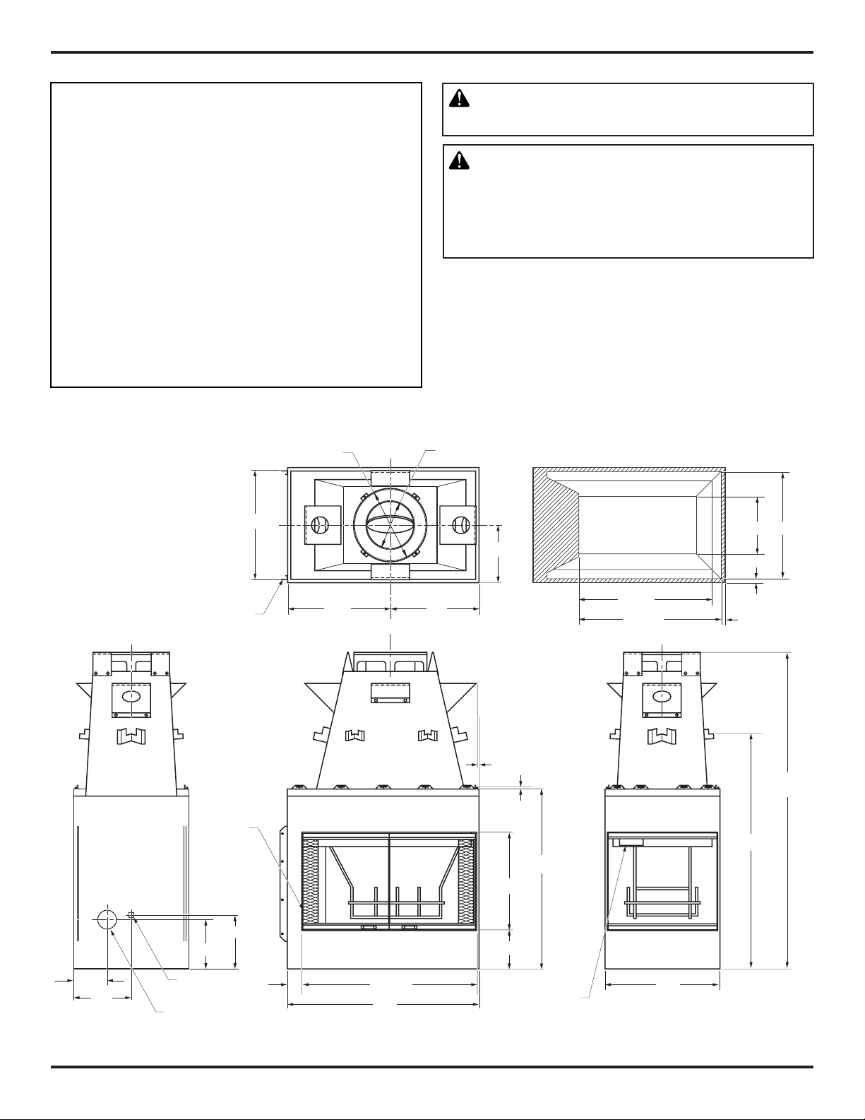
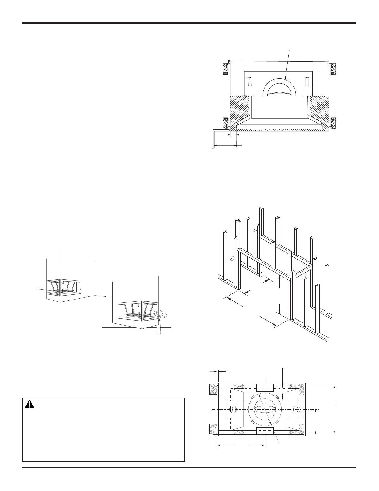
PRODUCT DIMENSIONS
15" O.D.
WARNING: Always leave glass doors fully opened
or fully closed when operating fireplace.
WARNING: Children and adults should be alerted
to the hazards of high surface temperatures and to
stay away to avoid burns or clothing ignition. Young
children should be carefully supervised when in the
same room as fireplace.
3
12
/8" I.D.
22
Nailing Flanges
Outside Air
Handle
Other Side
5
/8"
21" 19"
12"
5/8"
20
3/8"
1
/2"
37
1
24
/2"
1
/2"
29
1
/2"
12" 22 3/8"
3/4"
3/4"
66
1
48
/2"
1
/4"
1
/4"
7"
12"
1
10
/4"
Gas Line
Conduit
Outside Air
11
3"
36
40"
1
/2"
1
/8"
8
Certification
Label Behind Door
on Smoke Shelf
24"
Figure 1 - Dimensions
4
www.Superiorfireplaces.US.com
126616-01A
Page 5
FIREPLACE INSTALLATION
SELECTING LOCATION
To determine safest and most efficient location for fireplace, you
must take into consideration the following guidelines:
1. The location must allow for proper clearances (see Figure 2).
2. Consider a location where the fireplace will not be affected by
drafts, air conditioning ducts, windows or doors.
3. A location that avoids the cutting of joists or roof rafters will
make installation easier.
4. If an outside air kit is to be installed, accessibility to outside
combustion air must be considered. This can also be achieved
through a vented crawl space in some cases (see Optional
Outside Air Kit on page 7).
5. If gas line is to be installed, consider location of gas supply.
6. Do not connect this fireplace to a chimney system other than
an IHP chimney system.
7. Install in an area providing ventilation and adequate combustion air.
8. Due to high temperatures, do not locate this fireplace in high
traffic areas or near furniture or draperies.
9. Provide adequate clearances around air openings into combustion chamber. NEVER obstruct front opening of fireplace or flow
of combustion and ventilation air.
10. Do not locate in or near an area where gasoline or other flammable liquids may be stored. The firebox area must be kept clear
and free from these combustible materials.
The typical installation for this fireplace is a projected installation
which allows you to extend the fireplace any distance into the room. A
projection may be ideal for a new addition on an existing, finished wall.
Spacers on Sides of Fireplace
Provide Required 1" (2.5 cm)
Clearance
3" (7.6 cm)
12" (30.4 cm) Min. From Perpendicular
Side Wall to Fireplace Opening (Typ.)
2" (5 cm) Min. Clearance
From Pipe to Combustibles
Figure 3 - Firebox Clearances
FRAMING
1. Frame opening for fireplace using dimensions shown in Figures
5, 7 and 8 on pages 5 and 6 depending on your installation.
Figure 2 - Common Location of Fireplace
MINIMUM CLEARANCE TO COMBUSTIBLES
Back and sides of fireplace 1/2" minimum*
Adjacent wall 12" minimum
Chimney outer pipe surfaces 2" minimum
Bottom of fireplace to floor 0" minimum
WARNING: DO NOT PACK REQUIRED AIR SPACES
WITH INSULATION OR OTHER MATERIALS.
Do not obstruct fireplace openings (ie. louvers, etc.)
with any type of facing material. Combustible material must not be in contact with back of front face of
fireplace.
"
8
/
5
23
(60cm)
39 3/4"
(101cm)
Min.
43
1
(109.8cm)
/4"
Figure 4 - Framing Firebox
1/2" Min.
To Combustibles
21 1/2"
Figure 5 - Framing Clearances
2" Min. Clearance
from Outer Pipe
to Combustibles
5
11
/16"
Ø15 Outer Pipe
22
5
/8"
126616-01A
www.Superiorfireplaces.US.com
5
Page 6
FIREPLACE INSTALLATION Continued
2. If fireplace is to be installed directly on carpeting, tile (other than
ceramic) or any combustible material other than wood flooring,
fireplace must be installed upon a metal or wood panel extending
full width and depth of fireplace.
3. Set fireplace directly in front of this opening and slide unit back
until nailing flanges touch side framing.
4. Check level of fireplace and shim with sheet metal if necessary.
5. Before securing fireplace to prepared framing, ember protector
(provided) must be placed between hearth extension (not supplied) and under bottom front edge of fireplace to protect against
glowing embers falling through (see Figure 7). If fireplace is to
be installed on a raised platform, a Z-type ember protector (not
supplied) must be fabricated to fit your required platform height
(see Figure 6). The ember protector should extend under fireplace
a minimum of 1 1/2". The ember protector should be made of
galvanized sheet metal (28 gauge minimum) to prevent corrosion.
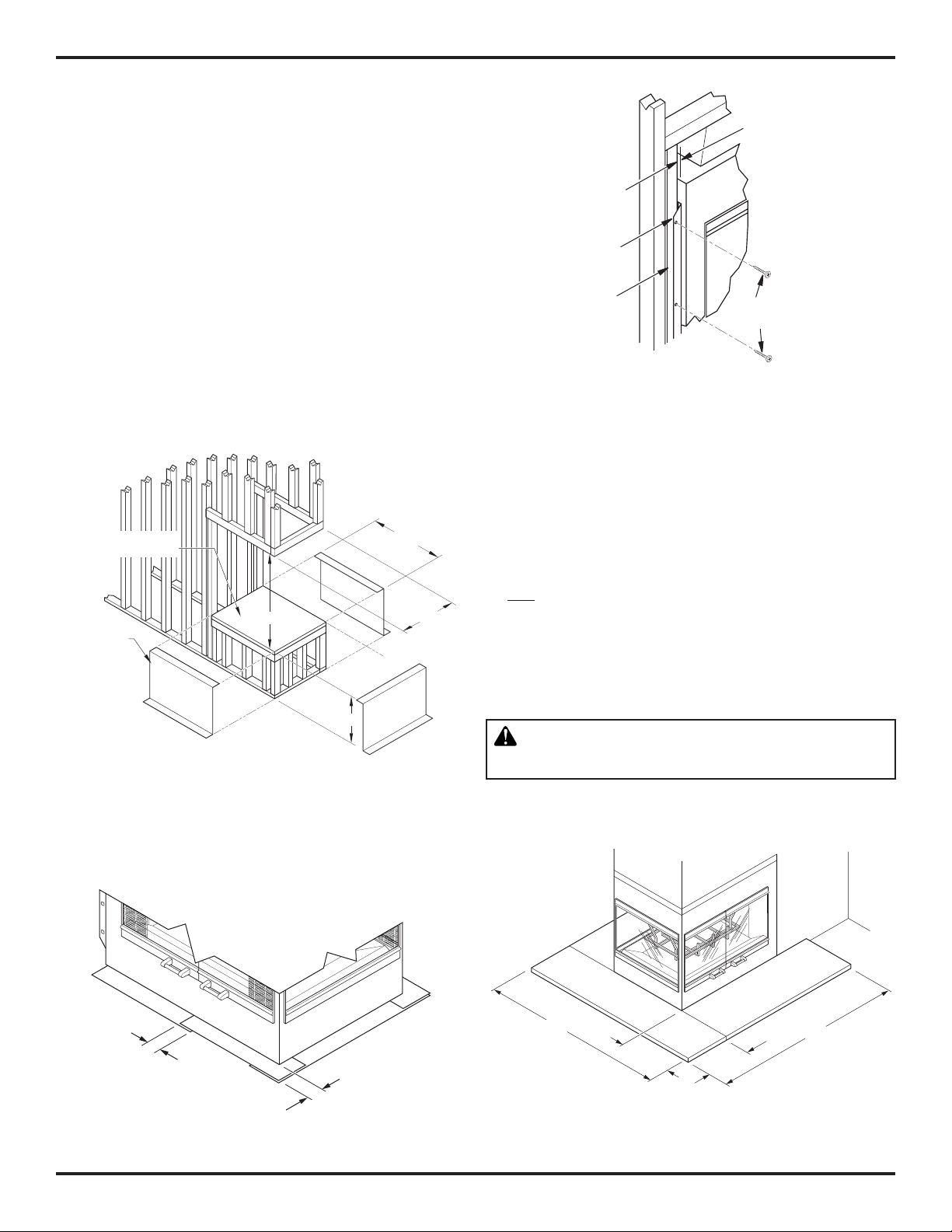
6. Using screws or nails, secure fireplace to framing through flanges
located on sides of fireplace (see Figure 8).
Platform Must Be Solid,
Flat, and Fully Supported
“Z” Type Metal
Safety Shields
Not Supplied
48
1
/2" Min.
39
7
/8"
5
22
/8"
1/2"
Minimum to
Combustibles
Nailing
Flanges
Prepared
Framing
Nails or
Screws
Figure 8 - Nailing Flanges
HEARTH EXTENSIONS
A hearth extension projecting a minimum of 20" in front of and a
minimum of 12" beyond each side of fireplace opening is required
to protect combustible floor construction in front of fireplace (see
Figure 9). Fabricate a hearth extension using a material which meets
the following specifications: a layer of noncombustible, inorganic
material having a thermal conductivity of k = .84 BTU IN/FT2 HR °F
(or less) at 1" thick. For example, if material selected has a k factor
of 0.25, such as glass fiber, the following formula would apply:
0.25 x 1.0" = 0.30" thickness required
0.84
Thermal conductivity "k" of materials can be obtained from manu-
facturer or supplier of noncombustible material.
If hearth extension is to be raised, a “Z” type ember protector must
be used (see Figure 6 and Figure 10, page 7).
*
*As Required by Design
As Long as Ceiling
Clearance is Maintaned
Figure 6 - Framing Firebox with “Z” Type Ember Protectors
1/2" MIN.
OVERLAP
1/2" MIN.
Figure 7 - Ember Protectors
WARNING: Hearth extension is to be installed
only as shown in Figure 9.
64" Min.
20" Min.
16"
Min.
Figure 9 - Hearth Extension
65" Min.
6
www.Superiorfireplaces.US.com
126616-01A
Page 7

FIREPLACE INSTALLATION Continued
2" X 4" Stud
Noncombustible
Hearth
Extension
8" Max.
1
1
/2" Typ.
Noncombustible
Hearth Extension
“Z” Type Ember
Protector
“K” Factor
.84
VENTING INSTALLATION
OPTIONAL OUTSIDE AIR KIT (MODELS AK4 OR AK4F)
The installation of an outside air kit should be performed during
the rough framing of the fireplace due to the nature of it’s
location. Outside combustion air is accessed through and exterior
wall (AK4) or a vented crawl space (AK4F). See Figure 13 and
Accessories on page 16.
Avoid installing outside air eyebrow in areas where inlet opening
may be blocked by snow, bushes or other obstacles. It should also
be located beyond the reach of children.
CAUTION: Combustion air inlet ducts shall not
terminate in attic space.
The maximum height for the air vent can not exceed
3feetbelowtheuegasoutletofthetermination.
1
1
/2" Typ.
Ember Protector
Figure 10 - Raised Hearth Extension
MANTEL CLEARANCES
Woodwork such as wood trims, mantels or any other combustible
material projecting from the front face must not be placed within 9"
of firebox effective opening.
Combustible materials above and projecting more than 1 1/2" from the
firebox front face (see Figure 11) must not be placed less than 12"
from effective opening of the firebox (NFPA STD 211, Sec. 7-3.3.3).
Mantels or any other combustible material may also come up to the
side edge of the black metal face of the firebox only if the projection
from the front face falls within limits shown in Figure 12.
Drywall
Combustible
Materials
33°
6" Nom.
(15.2 cm)
12" Min.
(30.4 cm)
9" Min.
Front
Face
Fireplace Front View
(22.8 cm)
Fireplace Side View
3" Nom.
(7.6 cm)
1
/2" Max.
1
(3.8 cm)
For further details on installation of outside air kit, please refer to
instructions included with air kit. For operating instructions, please
refer to your owner’s manual.
Secure to Collars with Metal Tape, Screws
or Straps (Min. of 1/4" x 20" in size)
Air Inlet
Location
Must Allow
For Bushes
or Snow
Air Inlet
Eyebrow
Vented Crawl Space (Check
Local Codes Before Installing in a
Vented Crawl Space)
Vent Hood
Required for
Wall Installation
Figure 13 - Air Kit Installation
Figure 11 - Mantel Clearances to Combustible Materials
Seal Gaps with
Noncombustible
Mortar or Adhesive
3
4
/8"
Min.
(11.1 cm)
3
2
/4" Max.
(6.98 cm)
Combustible
Material Must
Not Overlap
Black Metal
Front Face
Drywall
4"
(Approx.)
(10.1 cm)
Top View of Fireplace
33°
Nom.
6" Nom.
(15.2 cm)
Figure 12 - Mantel Clearances to Metal Face
126616-01A
www.Superiorfireplaces.US.com
7
Page 8

VENTING INSTALLATION Continued
CHIMNEY PIPE
The IHP chimney system is a snap-lock, double-wall pipe. It consists
of a stainless steel inner flue pipe(s), a galvanized outer pipe and a
wire spacer. Each section of pipe comes in lengths of 12", 18", 36"
and 48". The actual lineal gain for each is measured after each section
is fully connected. Lineal gain is the actual measurable length of a
part after two or more parts are connected.
LINEAL GAIN
PART NO. DESCRIPTION GAIN
WRT40PFWS Peninsula Fireplace 52 3/4"
48-12DM
48-12TM
36-12DM
48-12TM
24-12DM
48-12TM
18-12DM
48-12TM
12-12DM
48-12TM
STL-12D
RLT-12D
Flue Pipe 46 5/8"
Flue Pipe 34 5/8"
Flue Pipe 22 5/8"
Flue Pipe 16 5/8"
Flue Pipe 10 5/8"
Chase Style
Termination
Round Top
Termination
1" to 12"
7
"
USING ELBOW OFFSETS AND SUPPORTS
Chimney weight above offset rests on return elbow. Straps must be
securely nailed to rafters or joists (see Figure 15).
To achieve desired offset, you may install combinations of 12", 18",
36" and 48" length of double wall pipe (see offset chart and Figure 16).
Maximum length of pipe between supports is 6 feet of angled run. A
maximum of two 6 feet angled run sections per chimney system (see
Figure 18).
SUPPORT SECTIONS
The chimney support section is a 4" strap and 12" length of pipe.
A chimney support is required every 30 feet above fireplace after a
straight chimney run or above a return elbow after a straight chimney
run (see Figure 17, page 9). This support is designed to relieve the extra
weight load on fireplace and elbows when high chimneys are installed.
12S-12DM
Support
30 FT.
(9.14m)
Required
30 FT.
(9.14m)
PIPE INSTALLATION
The pipe sections must be assembled independently as the chimney
is installed. When connecting chimney directly to the fireplace, the
inner flue pipe section must be installed first with the lanced side up.
The outer pipe section can then be installed over the flue pipe section
with the hemmed end up. Press down on each pipe section until the
lances securely engage the hem on the fireplace starter. The wire will
assure the proper spacing between the inner and outer pipe sections.
Continue to assemble chimney sections as outlined above, making
sure that both the inner and outer pipe sections are locked together.
When installing double wall snap-lock chimney together, it is important to assure the joint between the chimney sections is locked. Check
by pulling chimney upward after locking. The chimney will not come
apart if properly locked. It is not necessary to add screws to keep the
chimney together (exception, see Figure 17, page 9).
WARNING: The opening in collar around chimney
at top of fireplace must not be obstructed. Never use
blown insulation to fill chimney enclosure.
15"
Galvanized
Outer Pipe
12 3/8''
Stainless Inner
Pipe Lanced
Side Up
Hemmed
End
Figure 15 - Elbow Offset
OFFSET
RISE CHIMNEY LENGTH
A B 48" 36" 18" 12"
4 3/8" 16 3/8"
9 1/2" 25 1/4"
12 1/2" 30 3/8"
14 3/8" 34"
17 5/8" 39 1/4"
21 1/2" 46"
22 3/4" 48 1/8"
26 3/8" 54 7/8"
26 3/8" 60"
31 3/4" 63 3/4"
34 3/4" 69"
38 5/8" 75 5/8"
39 7/8" 77 7/8"
43 3/4" 84 1/2"
46 3/4" 87 3/4"
48 7/8" 93 3/8"
ELBOW SET ONLY
1
1
1 1
1
1 2
1
1 1
1 1
1 1
2
1 1 1
1 1
2 1
2
OFFSET CHART
Figure 16 - Raise and Offset
Return
Elbow
2
Screws
B
A
Figure 14 - Pipe Connection
8
www.Superiorfireplaces.US.com
126616-01A
Page 9

2" (5.1cm)
Minimum
VENTING INSTALLATION Continued
Angled Firestop
Existing
Ceiling
Frame
Firestop
Spacer
Straps
6' Max.
(15.2 cm)
6' Max.
(15.2 cm)
Ceiling
Support
Return
Elbow
Figure 17 - Chimney Supports
6' Max.
(15.2 cm)
6' Max.
(15.2 cm)
6' Max.
(15.2 cm)
6' Max.
(15.2 cm)
Screws or
Staples
(Min. of 8)
Figure 19 - Firestop Spacer with Living Space Above Ceiling
Screws or Staples
Firestop
(Min. of 8)
Spacer
Existing
Ceiling
Frame
Figure 20 - Firestop Spacer with Attic Space Above Ceiling
10' FOOT RULE
All chimney terminations must extend a minimum of 3 feet above the
highest point where it passes through the roof and must be at least 2
feet above roof with a 10 foot horizontal span (see Figure 21).
IMPORTANT: If an exposed portion of chimney is greater than 4 feet
above the roof line, use support wires to keep chimney secure. Support
wires may be attached to outer pipe of chimney with screws, if screws
do not penetrate inner flue pipe.
Figure 18 - Typical Offset Installations
FIRESTOP SPACERS (FS-10)
Firestop spacers are required at each point where the chimney penetrates a floor or ceiling joist space. Their purpose is to establish
and maintain the required clearance between the chimney and the
combustible materials. When the pipe passes through a framed
opening into a living space above, the firestop must be placed onto
the ceiling from below as shown in Figure 19.
They also provide complete separation from one floor space to
another or attic space as required by most codes. When the double
wall pipe passes through a framed opening into an attic space, the
firestop must be placed into an attic floor as shown in Figure 20.
When penetrating a floor or ceiling at an angle, use firestop spacer
number 30FS-10 (see Replacement Parts, page 15 and Accessories,
page 16).
126616-01A
www.Superiorfireplaces.US.com
Figure 21- 10 Foot Rule
9
Page 10

VENTING INSTALLATION Continued
MINIMUM/MAXIMUM CHIMNEY HEIGHT
The minimum height of the chimney (measured from the base of the
fireplace to the flue gas outlet-end of pipe) is 16 feet for a straight run,
16 feet minimum for a run with 1 elbow set and 25 feet minimum for
a run with 2 elbow sets. (A set consists of one starter elbow and one
return elbow.)
Uncommon circumstances such as neighboring hills, tall trees, or
strong wind areas can cause down drafts in chimney system. In such
cases, going beyond the minimum recommended height would be
preferable to provide a better draw.
The fireplace height approved for any chimney run with this fireplace
system is 40 feet measured from bottom of firebox to flue outlet-end
of pipe (see Figure 22).
WARNING: Do not operate an unvented gas log
set in this fireplace with the chimney removed.
PENETRATING ROOF
To maintain a 2" clearance to pipe on a roof with a pitch, a rectangular
opening must be cut.
1. Determine center point where pipe will penetrate the roof.
2. Determine center point of the roof. Pitch is the distance the roof
drops over a given span, usually 12". A 6/12 pitch means that the
roof drops 6" for each 12" one measure horizontally down from
roof rafters.
3. Use roof opening chart (Figure 23) to determine correct opening
length and flashing required.
4. Remove shingles around opening measured. Cut out this section.
5. Add next sections of pipe until end penetrates roof line. Check to see
that proper clearances are maintained. Extend chimney by adding
sections of double wall pipe until pipe is minimum of 30" above
highest point of roof cutout. Termination and chimney must extend
a minimum of 36" above highest point where it passes through the
roof (see 10-Foot Rule and Figure 21, page 9.
RLT-12D RLT-12D STL-12D
Storm
Collar
Flashing
Minimum
Height
15 Ft.
Firestop
Spacer
Maximum
Height
Chase
Te rmination
50 Ft.
19" Min.
(48.26cm)
2" Min.
(5.08cm)
2" Min.
(5.08cm)
2" Min.
(5.08cm)
Opening
“A”
Pitch Slope Opening "A"
Max.
Used Flashing
Model No.
Flat 0° 19" V6F-10DM
0-6/12 26.6° 23.25" V6F-10DM
6/12-
12/12
45° 30.75" V12F-10DM
Figure 23 - Roof Opening Measurements
30" Min.
(76.2cm)
FLASHING INSTALLATION
Determine flashing to be used with roof opening chart. Slide flashing
over pipe until base is flat against roof. Replace as many shingles as
needed to cover exposed area and flashing base. Secure in position
by nailing through shingles (see Figure 24). DO NOT NAIL THROUGH
FLASHING CONE.
Figure 22 - Maximum Chimney Height
10
www.Superiorfireplaces.US.com
126616-01A
Page 11

VENTING INSTALLATION Continued
Storm Collar
Overlap
Shingles Top
Flashing
Cone
Nail Only Outer
Perimeter of
Flashing
Underlap Shingles
at Bottom
Figure 24 - Flashing Installation
STORM COLLAR INSTALLATION (SC-10)
Place storm collar over pipe and slide down until it is snug against
the open edge of the flashing (see Figures 24 and 25). Apply waterproof caulking to all seams and notches around storm and also at
base around shingles.
and Sides Only
Stainless
Inner Flue
Pipe
Secure
Termination
to Outer
Pipe with 3
Screws
Overlap
Shingles (Top and
Sides of Flashing Base)
Figure 26 - Terminations
RLT-12D
Chase
Top
1" Noncombustible
Spacer
Apply
Waterproof
Caulking
Screen
1"
Space
Storm
Collar
Flashing
Underlap
Shingles
Chimney
Pipe
Storm
Collar
Waterproof
Caulk
Flashing
Figure 25 - Storm Collar
TERMINATIONS
Standard Installation
The fireplace system must be terminated with the listed round top or
chase terminations. In any case, refer to the installation instructions
supplied with the termination.
Terminations approved for this fireplace are RLT-12D, which can be
used for flashing or chase and STL-12D for chase style termination
only. Figure 26, shows an RLT-12D round top termination.
Follow installation instructions provided with termination being used.
CAUTION: Do not seal openings on the rooftop
ashing.Followtheinstallationinstructionsprovided
with the termination being used.
CHASE INSTALLATIONS
Instructions for chase installations are included with the chase style
termination chosen. In a multiple chase installation, be sure to provide
adequate distance between terminations to prevent smoke spillage
from one termination to another. Terminations must be separated a
minimum of 30" center to center and stacked at a minimum vertical
height difference of 18" (see Figure 27).
Note: If a decorative shroud is to be installed, contact the manufacturer for specifications.
18"
Min.
Typ.
30" Min.
126616-01A
www.Superiorfireplaces.US.com
30" Min.
Figure 27 - Multiple Chase Installation
11
Page 12

VENTING INSTALLATION Continued
FINISHING FIREPLACE
Combustible materials, such as wallboard, gypsum board, sheet
rock, drywall, plywood, etc. may make direct contact with sides
and top around the fireplace face. It is important that combustible
materials do not overlap the face itself. Brick, glass, tile or other
noncombustible materials may overlap the front face provided they
do not obstruct essential openings like louvered slots or any other
opening. When overlapping with a noncombustible facing material,
use only noncombustible mortar or adhesive.
INSTALLING FIREPLACE FACING.
Any noncombustible material may be used for facing (glass, tile,
brick, etc.) as long as proper clearances are adhered to and fireplace
openings are not obstructed in any way (see Minimum Clearance to
Combustibles, page 5 and Figure 28).
Use only heat resistant, noncombustible mortar or adhesive when
securing facing material to front of fireplace. When placing facing at
upper edge of effective opening of fireplace, provide “L” shaped piece
of metal extending full width of opening (see Figure 28).
Secure with sheet metal screws at a distance high enough from edge
so it doesn't interfere with operation of doors. This assures that facing material will not block openings.
Noncombustible
Facing Material
“L” Shaped
Metal
Support
Do Not
Block
Opening
Noncombustible
Facing Material
Figure 28 - Fireplace Facing (Your Fireplace May Vary from
Illustration)
12
www.Superiorfireplaces.US.com
126616-01A
Page 13

OPTIONAL GAS LINE INSTALLATION
WARNING: A qualified service person must con-
nect fireplace to gas supply. Follow all local codes.
A gas line may be installed for the purpose of installing a vented
or vent-free decorative gas appliance available through your local
distributor. Use only gas piping approved by local codes. When
installing a gas line, a shutoff valve designed for installation outside
the appliance is recommended.
The gas pipe is intended for connection to a decorative gas appliance that operates using natural or propane/LP gas only. This
appliance must have an automatic shutoff device and must comply
with the Standard for Decorative Gas Appliances for Installation in
Vented Fireplace, ANSI Z21.60. ONLY UNVENTED GAS LOG SETS
WHICH HAVE BEEN FOUND TO COMPLY WITH THE STANDARD FOR
UNVENTED ROOM HEATERS, ANSI Z21.11.2, ARE TO BE INSTALLED
IN THIS FIREPLACE.
NOTICE: Before you proceed, make sure your gas supply is turned off.
Use only a 1/2" black iron pipe and appropriate fittings.
1. Remove knockout indentation on refractory or firebrick wall
located approximately 2" above the refractory hearth floor. The
knockout indentation must be firmly tapped with any solid object
such as a 1/2" dowel until it is released. Remove fragmented
portions of refractory (see Figure 29).
2. Remove gas line cover plate located on rear of fireplace and pull
out insulation from gas line conduit sleeve. Save insulation for
reuse.
3. Run 1/2" black iron gas line into the firebox through the rear at
11 1/4" from floor and through gas line conduit sleeve (if using
a raised platform, add height). Provide sufficient gas line into
firebox chamber for fitting connection (see Figure 30).
Note: Secure incoming gas line to wood framing to provide rigidity
for threaded end.
4. Repack insulation around gas line and into sleeve opening. Seal
any gaps between gas line and refractory knockout hole with
refractory cement or commercial furnace cement, Install the gas
appliance or cap off gas line if desired.
If you install a decorative gas appliance (vented gas log), decorative
gas appliance must comply with the Standard for Decorative Gas
Appliance for Installation in Solid Fuel Burning Fireplaces, ANSI
Z21.60/CSA 2.26 or Z21.84 and shall also be installed in accordance
with ANSI Z223.1/NFPA 54 National Fuel Gas Codes (USA) and CAN/
CGA-B149.1 National Gas And Propane Installation Code (Canada).
Outside of Fireplace
Gas Line
Conduit
Insulation
Gas
Conduit
Cover
Side
Firebrick
Finished
Side
1/2" Dowel
Refractory
Knockout
Plug
Figure 29 - Gas Line Knockout
Outside of
Fireplace
Gas
Line
Conduit
Repack
Insulation
Incoming
1/2" Black
Iron Pipe
Seal
Opening
with
Refractory
Cement
Side
Firebrick
Finished
Side
Provide Enough
Threaded End for
Fitting Connection
Figure 30 - Gas Line Installation
CAUTION: All gas piping and connections must be
tested for leaks after installation is completed. After
ensuring that gas valve is on, apply soap and water
solution to all connections and joints. Bubbles forming
show a leak. Correct all leaks at once. DO NOT USE
AN OPEN FLAME FOR LEAK TESTING AND DO NOT
OPERATE ANY APPLIANCE IF A LEAK IS DETECTED.
LEAK TESTING SHOULD BE DONE BY A QUALIFIED
SERVICE PERSON.
Note: An IHP hood must be installed when using an unvented gas
log set (see Accessories on page 16).
WARNING: Do not operate an unvented gas log
set in this fireplace with chimney removed.
126616-01A
www.Superiorfireplaces.US.com
WARNING: To avoid the risk of damaging fireplace
materials and increasing the risk of spreading a fire,
do not use fireplace to cook or warm food.
WARNING: If the fireplace has been used for wood
burning, firebox and chimney must be cleaned of soot,
creosote and ashes be a qualified chimney cleaner.
Creosote will ignite if heavily heated.
WARNING: When using a decorative vented gas
log, damper must be removed or permanently locked
in fully open position and glass doors must be in fully
open position.
13
Page 14

OPERATION AND MAINTENANCE GUIDELINES
GLASS DOORS
Cabinet type glass doors are optional with this fireplace. Check with
your local distributor for availability.
To install glass doors, refer to installation instructions that are included with kit. When fireplace is in operation, doors must be fully
open or fully closed position only or a fire hazard may be created
(see Figure or 31).
A fireplace equipped with glass doors operates much differently
than a fireplace with an open front. A fireplace with glass doors has
a limited amount of air for combustion. Excessive heat within the
fireplace can result if too large a fire is built or if combustion air gate
is not completely open.
IMPORTANT: The following tips should be used to assure that both
fireplace and glass door retain their beauty and function properly.
• Both the flue damper and glass doors must be fully opened
before starting a fire. This will provide sufficient combustion
air and maintain safe temperatures in firebox.
• The glass must be allowed to warm slowly and evenly. The tempered glass will withstand a gradual temperature rise to 550° F,
which is more than a normal fire will generate. Such materials
as pitch/wax laden logs, very dry mill end lumber and large
amounts of paper or cardboard boxes. Always keep the fire well
back from the doors and never allow flames to contact the glass.
Cleaning Glass
Clean glass with any commercial glass cleaner or soap and water.
Do not use any abrasive material to clean glass. Do not clean glass
with any cool water if glass is still hot from the fire. To remove doors,
refer to instructions included with glass door kit.
DAMPER MECHANISM
The damper control lever is located inside the fire chamber (see Figure 32). Make sure lever is cool before handling. Pull down to close
and push up to open. Damper must be open when lighting a fire.
Not doing so will cause smoke spillage into the room. When firebox
is not in use, close damper to prevent down drafts to enter room.
GRATE
" WARNING: FIREPLACES EQUIPPED WITH DOORS
SHOULD BE OPERATED ONLY WITH DOORS FULLY
OPEN OR DOORS FULLY CLOSED. IF DOORS ARE LEFT
PARTLY OPEN, GAS AND FLAME MAY BE DRAWN OUT
OF THE FIREPLACE OPENING, CREATING RISKS OF
BOTH FIRE AND SMOKE".
OUTSIDE AIR
HANDLE
DAMPER CONTROL LEVER
PULL DOWN TO CLOSE
PUSH UP TO OPEN
Figure 32 - Damper Operation
OUTSIDE AIR MECHANISM
The outside air handle is located at the right hand side of firebox
rear refractory (see Figure 32). Pull to close, push to open. Always
open mechanism when starting a fire. This provides adequate outside
combustion air. Close mechanism when not in use to prevent cold
air from entering room. Periodically check your outside air intake
vent hood for any possible obstructions such as snow, bushes, etc.
PULL TO CLOSE
PUSH TO OPEN
Glass Doors Must be Fully Open
(as Shown) or Fully Closed when
Appliance is in Operation
Figure 31 - Cabinet Glass Doors
14
www.Superiorfireplaces.US.com
126616-01A
Page 15

OPERATION AND MAINTENANCE GUIDELINES
Continued
GRATE
The grate is designed to provide you with the maximum solid fuel
capacity. Do not overload grate or obstruct required air space beneath
it. Doing so may cause smoke spillage and a fire hazard. Always keep
ashes from building up under grate.
WARNING: Risk of fire! Replace grate with IHP
model 11150 grate only. This grate has been designed to keep the operation of your fireplace safe
and efficient.
Never obstruct flow of combustion and ventilation air. Keep front of
fireplace clear of all obstacles and materials.
CHIMNEY
Have your chimney system cleaned and inspected regularly to ensure safe
and efficient operation.
For further operating guidelines, instructions and warranty information, please refer to your homeowner's guide or contact your dealer.
REPLACEMENT PARTS
Note: Use only original replacement parts.
This will protect your warranty coverage for parts replaced under
warranty.
Contact authorized dealers of this product. To locate a dealer in your
area contact IHP at 1-800-655-2008. You can also visit our web site
at www.Superiorfireplaces.US.com.
When calling your dealer, have ready:
• your name
• your address
• model and serial numbers of your fireplace
• how fireplace was malfunctioning
• purchase date
Usually, we require that the part is returned to the factory.
TECHNICAL SERVICE
You may have further questions about installation, operation, or
troubleshooting. Please contact your IHP dealer for any questions
or concerns a. When calling your dealer please have your model and
serial numbers of your fireplace ready. You can also visit our web
site at www.Superiorfireplaces.US.com.
WARNING: Children and adults should be alerted
to the hazards of high surface temperatures and to
stay away from these to avoid burns or clothing ignition. Young children should be carefully supervised
when they are in the same room as fireplace.
126616-01A
www.Superiorfireplaces.US.com
15
Page 16

This list contains replaceable parts used in your fireplace.
PARTS
GRATE , 10''
11150
CHIMNEY SUPPORT
12S-12DM (Also available in triple wall)
EMBER PROTECTORS
20093
ACCESSORIES
ADJUSTABLE HOOD
Black Painted Finish - GA6050
Antique Brass Finish - GA6053
Required when installing a vent-free gas log in this fireplace.
DOUBLE WALL 30° ELBOW/OFFSET
30E-12DM (Also available in triple wall)
Starter
Elbow
Return
Elbow
DOUBLE WALL PIPE
12-12DM, 18-12DM, 24-12DM, 36-12DM, 48-12DM
(Chimney pipe assembly includes outer and inner pipes and
comes with wire spacer. Also available in triple wall.)
FIRESTOP SPACER
FS-10 for Straight Pipe
30FS-10 for 30° Angled Run
STORM COLLAR
SC2-1
16
www.Superiorfireplaces.US.com
126616-01A
Page 17

ACCESSORIES Continued
ROOF FLASHING
0 TO 6/12 PITCH - V6F-10DM
6/12 TO 12/12 PITCH - V12F-10DM
ECONO TOP TERMINATION
STL-12DM
OUTSIDE AIR KIT FOR FLOOR INSTALLATION
AK4
Vent Hood
Connector
Duct - 4" x 3'
Vent Plaster
Collar
BI-FOLD GLASS DOOR
DG36PN (Brushed Brass)
DC36PN (Platinum)
DBPPN36 (Black)
ROUND TOP TERMINATION
RTL-12D
126616-01A
www.Superiorfireplaces.US.com
17
Page 18

NOTES
______________________________________________________
______________________________________________________
______________________________________________________
______________________________________________________
______________________________________________________
______________________________________________________
______________________________________________________
______________________________________________________
______________________________________________________
______________________________________________________
______________________________________________________
______________________________________________________
_____________________________________________________
______________________________________________________
______________________________________________________
______________________________________________________
______________________________________________________
______________________________________________________
______________________________________________________
______________________________________________________
______________________________________________________
______________________________________________________
______________________________________________________
______________________________________________________
______________________________________________________
_____________________________________________________
______________________________________________________
______________________________________________________
______________________________________________________
______________________________________________________
______________________________________________________
______________________________________________________
______________________________________________________
18
www.Superiorfireplaces.US.com
126616-01A
Page 19

NOTES
______________________________________________________
______________________________________________________
______________________________________________________
______________________________________________________
______________________________________________________
______________________________________________________
______________________________________________________
______________________________________________________
______________________________________________________
______________________________________________________
______________________________________________________
______________________________________________________
_____________________________________________________
______________________________________________________
______________________________________________________
______________________________________________________
______________________________________________________
______________________________________________________
______________________________________________________
______________________________________________________
______________________________________________________
______________________________________________________
______________________________________________________
______________________________________________________
______________________________________________________
_____________________________________________________
______________________________________________________
______________________________________________________
______________________________________________________
______________________________________________________
______________________________________________________
______________________________________________________
______________________________________________________
126616-01A
www.Superiorfireplaces.US.com
19
Page 20

Innovative Hearth Products reserves the right to make changes at any time, without notice, in
design, materials, specifications, prices and also to discontinue colors, styles and products. Consult
your local distributor for fireplace code information.
P126616 01
Printed in U.S.A. © 2014 IHP LLC
P/N 126616-01 Rev. A 01/2014.
1508 Elm Hill Pike, Suite 108
Nashville, TN 37210
1-800-655-2008
www.IHP.US.com
 Loading...