

Superior 2010R, 3010R, 2020R, 3030R Owner's Manual

www.superiorwaterandair.com
801-974-9090 or 800-974-7638
OWNER’S MANUAL
MODEL “R” SERIES
2010R
2020R
3010R
3030R

Table of Contents
Introduction ..................................................................... Page 1
To shut the water off ....................................................... Page 1
Salt and water level ........................................................ Page 1
Operating The Water Softener
General information ........................................... Page 1
Programming the time of day ............................. Page 2
Immediate regeneration ..................................... Page 2
Holiday mode ..................................................... Page 2
Delayed regeneration ......................................... Page 2
The electronic timer ........................................................ Page 3
Service mode ..................................................... Page 3
Power failure ...................................................... Page 4
Timer failure ....................................................... Page 4
Programming .................................................................. Page 4
Diagnostic level .............................................................. Page 6
Fast program check ........................................................ Page 7
Parts replacement .......................................................... Page 8
Printed circuit board ........................................... Page 8
Drive motor ........................................................ Page 9
Injector ............................................................... Page 9
Back wash flow control ...................................... Page 10
Brine refill control ............................................... Page 10
Brine tee ............................................................ Page 10
Rotor assembly .................................................. Page 10
Seal disk ............................................................ Page 10
Gasket ............................................................... Page 11
Timer head ......................................................... Page 11
Worm drive shaft ................................................ Page 11
Impeller .............................................................. Page 12
Synchronizing valve body and timer head ......... Page 12
Troubleshooting .............................................................. Page 13
Annual Maintenance ....................................................... Page 16
Exploded Views & Part Numbers
Valve body ......................................................... Page 17
DIR Control ........................................................ Page 19

1
INTRODUCTION
Congratulations on having purchased a quality and well built Superior Water And Air water
softener. On a normal installation, your water softener should be connected to all of your
plumbing with the exceptions of your kitchen cold side and your outside faucets. Using three
valves that are generally located directly above the water softener makes the plumbing
connection. These three valves constitute the bypass, which look like the letter “H” when looking
at it. In the event that you should have to shut the water off to the water softener due to a leak,
continue with the following instructions.
TO SHUT THE WATER OFF ON THE SOFTENER
1.) Directly above the water softener are three valves. Turn the left and right valves
until they are perpendicular to the pipe
2.) Turn the middle valve open by turning it until it is going in the same directions as
the pipe. The water should now be turned off on the water softener and you should
now have unsoftened water to your house.
THE SALT AND WATER LEVEL INSIDE THE SALT TANK
It is recommended that the salt level not fall more than 3"(inches) below the water level inside
the salt tank. The water level inside a round salt tank is generally one to one-half feet deep. The
square salt tanks are generally about half to two-thirds full of water. Should the softener run out
of salt or you allow the salt level to drop down too far, you may experience hard and/or salty
water. To avoid this, we recommend keeping the salt tank full of salt or at least keeping the salt
level above the water level at all times. Should you experience salty water coming through your
plumbing, the quickest way to flush it out is running the cold water inside your bathtub until the
salt is all flushed out.
Your water softener will function with any type of salt; however our experience has shown us
that fewer problems will occur when using salt pellets. Salt pellets are cleaner, rarely have any
debris and they do not have a tendency to form salt bridges as does rock salt. Also rock salt, at
times, has a tendency to carry more dirt and debris with it, which in turns make your salt tank
appear very dirty inside and may cause it to have a foul odor. However, this dirt will not harm
the water softener.
OPERATING THE WATER SOFTENER
GENERAL INFORMATION
The control valve is designed to initiate regeneration according to the installer’s customized
parameters. Following the instructions contained in this section will allow the homeowner to
change the time of day, initiate the Holiday Mode program or to initiate a Delayed Regeneration.
These instructions are also found on the front of the control valve, behind the flip down cover.
The control valve utilizes a super capacitor to maintain time for minimum of 2 hours in the event
of a power loss. Should the power be out longer than 2 hours, it may be necessary to reset the
unit to the correct time of day.
NOTE: The control valve is an electronic item and therefore is sensitive to power surges just
like any other electronic item. For this reason, it is recommended that you have a surge
protector installed for the water softener.

2
PROGRAMMING THE TIME OF DAY
Pressing the scroll button enters the Time of Day programming mode. Once pressed the time
of day will start flashing. To adjust the time, press the up arrow or down arrow
IMMEDIATE REGENERATION
When the control valve is in service, the user requests an immediate regeneration by pushing the
scroll buttons three times. “REGENERATION IN 10 SEC “ message will show. The
regeneration will occur when the second counter reaches zero
HOLIDAY MODE
Regeneration is not allowed when the control valve is in the Holiday Mode. The word Holiday will
blink when scrolled to on the control board. After sixty seconds, the unit enters the Holiday Mode.
The only way the unit comes out of Holiday Mode is a flow rate greater that 1.5 gallons per minute
or if an immediate regeneration is started. Scrolling out of Holiday Mode is the last way to exit.
After exiting, the unit will go into an immediate regeneration.
DELAYED REGENERATION
While in service mode, the user requests a delayed regeneration by scrolling to the
“REGENERATION AT 02:00 “ message, by pushing the scroll button four times. Leave the
setting in this mode in order to initiate a delayed regeneration. Regeneration will occur when the
time clock reaches the delayed regeneration time. After the regeneration takes place, the clock will
return to the time of day.
NOTE: If at any time you have experienced hard water due to a malfunction of the equipment or
having ran low or out of salt, the water softener will need to be manually regenerated three nights
in-a-row or three times in-a-row with a minimum of two hours in between each manual
regeneration. To start a manual regeneration, follow the instructions for IMMEDIATE
REGENERATION.
3
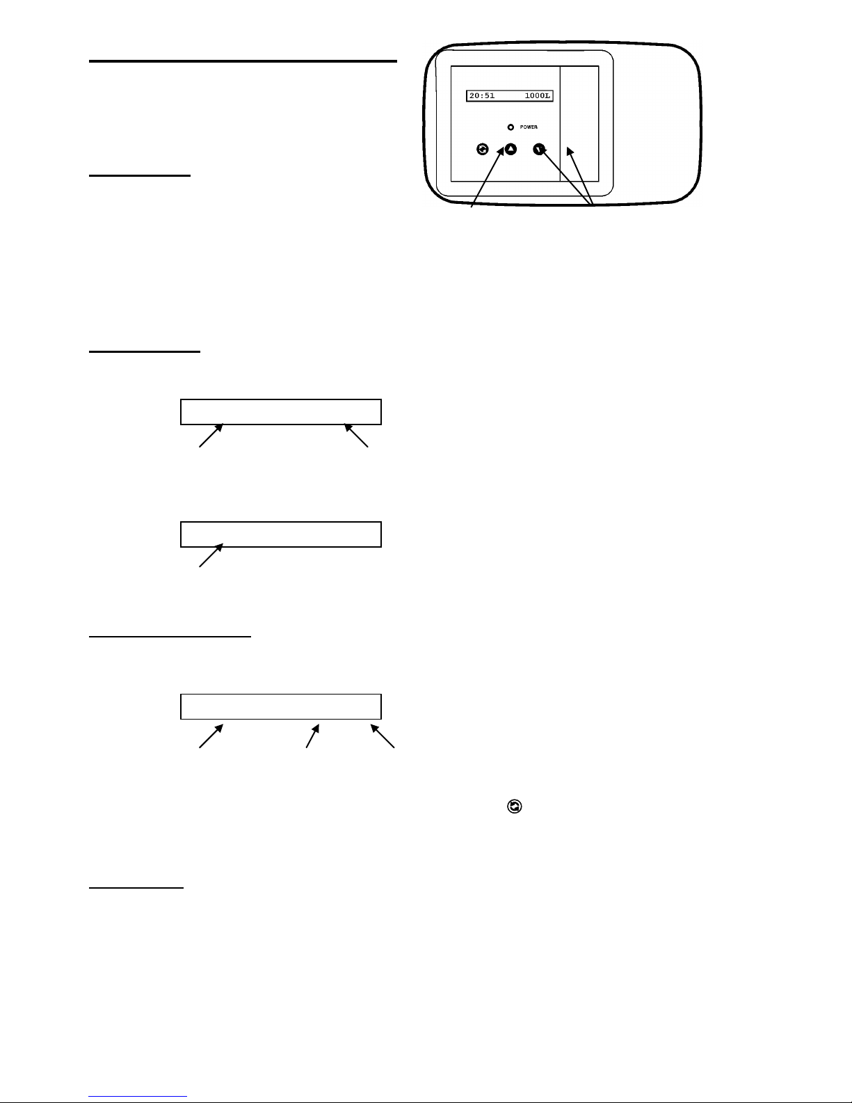
scroll button up / down buttons
to advance to adjust the
through the value of the
parameters parameter
The Electronic Timer
8:00 AM 1000GL
Regen 67 Cyc2:45
2:00 AM REGEN
Basic features
Control pad
The electronic timer uses a Printed Circuit Board (PCB),
equipped with a microprocessor and flash memory. All
programming is done by use of the 3-button control pad
with LCD-display.
Service mode
In service mode the display shows the time of day and remaining capacity:
time of day remaining capacity
When the remaining capacity equals the reserve capacity, the display will show the time of day and the indication
“REGEN”, indicating that a delayed regeneration will be started at the programmed time of regeneration:
time of day
Regeneration mode
In regeneration mode the display shows the total remaining regeneration time, the actual regeneration cycle and the
remaining cycle time:
total remaining actual regen. remaining
regen. time cycle cycle time
The control valve can be reset to service mode at any time by pushing the button, thus manually advancing it
through the regeneration cycles.
Flow meter
In service mode the display shows the time of day and remaining capacity; the remaining capacity counter counts back
per unit, i.e. per litre or gallon. By opening a faucet after the unit, the correct functioning of the flow meter can be
checked by means of this counter.
4
Power failure
Service Required
In the event of a power failure, the program remains stored in the flash memory, while an incorporated SuperCap
(capacitor) will maintain the correct time of day during a period of several hours; consequently, in case of prolonged
power failure, the time of day might not be maintained; if this happens, the time of day indication will, when the power
supply is re-established, be flashing, indicating that the time of day needs to be set; refer to “Programming instructions
for the End-User level” to set the correct time of day.
When a power failure occurs when the holiday mode is activated, it will remain activated when power is restored,
providing that the incorporated SuperCap has maintained the time of day over the entire duration of the power failure.
When the power failure occurs during the execution of an automatic regeneration, the control valve will remain in it’s
last position; when the power supply is re-established, the control valve will return to the service position, stay there for
60 sec. and restart a complete regeneration from the beginning.
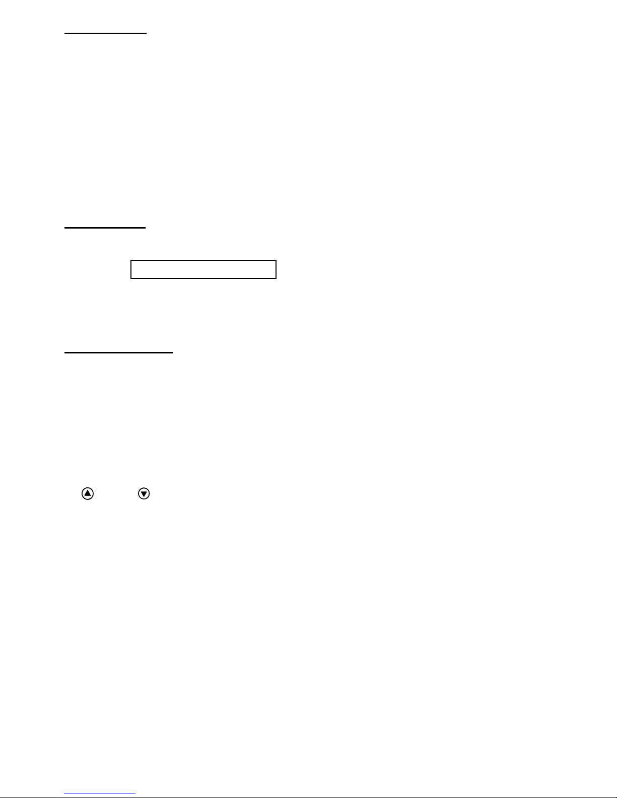
Timer failure
In the event of a timer failure, the display will show the message:
In such case, entering one of the programming levels can possibly solve the problem. However if the problem persists,
professional service is required.
Programming
!!! ATTENTION
During programming, it is necessary to enter the desired change within 5 minutes. Otherwise the microprocessor will
automatically break off the programming and return to the service mode, while all possibly entered changes to the
program are lost. If this occurs, it will be necessary to re-initiate the programming process.
All programming parameters are grouped into different user-specific levels (end-user / installer / OEM / factory).
The end-user level is accessible freely, no specific access code is required; in order to access one of the 3 other
specific levels, the proper access code, i.e. key sequence, needs to be entered.
In the programming modes, a flashing indication implicates that this parameter can be adjusted by pushing the
button or button; in this technical manual this is indicated by means of an italic font.
5
Programming instructions for the End-User level
Set 8:00 AM
Regen in 10 sec
Regen at 2:00 AM
Set 8:00 AM
Holiday
OFF
Holiday
ON
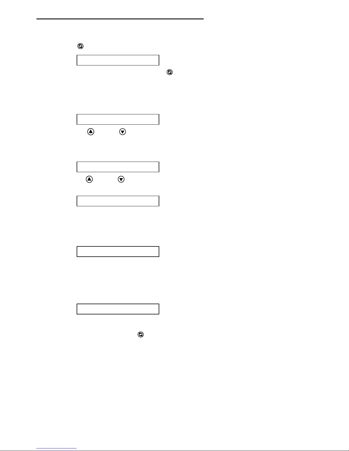
1. Accessing the End-User level:
Make sure that the control valve is in the service mode.
Push the button; the display will show:
You are now in the End-User level; use the button to advance through the different programming
parameters.
2. Available programming parameters:
1) Time of day setting:
The display will show:
Push the button or button to set the correct time of day.
2) Holiday mode:
The display will show:
Push the button or button to activate the holiday mode, meaning the unit will not regenerate; the
3) Immediate regeneration mode:
4) Delayed regeneration mode (not available in case regen. type is set to “Immediate” in the OEM level):
display will show:
The holiday mode is cancelled when a flow rate greater than 6 L/min is measured or when one of the
buttons is pushed. In either of these cases the unit will start an immediate regeneration.
The display will show:
If the control valve is left in this position, the countdown timer will countdown to 0 sec and start a
regeneration.
To cancel this mode, push the button before the countdown timer has reached 0 sec.
The display will show:
If the control valve is left in this position, the unit will perform regeneration at the programmed time of
regeneration.
To cancel this mode, push the button.
 Loading...