

Page 1

www.superiorwaterandair.com
801-974-9090 or 800-974-7638
OWNER’S MANUAL
MODEL “R” SERIES
2010R
2020R
3010R
3030R
Page 2

Table of Contents
Introduction ..................................................................... Page 1
To shut the water off ....................................................... Page 1
Salt and water level ........................................................ Page 1
Operating The Water Softener
General information ........................................... Page 1
Programming the time of day ............................. Page 2
Immediate regeneration ..................................... Page 2
Holiday mode ..................................................... Page 2
Delayed regeneration ......................................... Page 2
The electronic timer ........................................................ Page 3
Service mode ..................................................... Page 3
Power failure ...................................................... Page 4
Timer failure ....................................................... Page 4
Programming .................................................................. Page 4
Diagnostic level .............................................................. Page 6
Fast program check ........................................................ Page 7
Parts replacement .......................................................... Page 8
Printed circuit board ........................................... Page 8
Drive motor ........................................................ Page 9
Injector ............................................................... Page 9
Back wash flow control ...................................... Page 10
Brine refill control ............................................... Page 10
Brine tee ............................................................ Page 10
Rotor assembly .................................................. Page 10
Seal disk ............................................................ Page 10
Gasket ............................................................... Page 11
Timer head ......................................................... Page 11
Worm drive shaft ................................................ Page 11
Impeller .............................................................. Page 12
Synchronizing valve body and timer head ......... Page 12
Troubleshooting .............................................................. Page 13
Annual Maintenance ....................................................... Page 16
Exploded Views & Part Numbers
Valve body ......................................................... Page 17
DIR Control ........................................................ Page 19
Page 3

1
INTRODUCTION
Congratulations on having purchased a quality and well built Superior Water And Air water
softener. On a normal installation, your water softener should be connected to all of your
plumbing with the exceptions of your kitchen cold side and your outside faucets. Using three
valves that are generally located directly above the water softener makes the plumbing
connection. These three valves constitute the bypass, which look like the letter “H” when looking
at it. In the event that you should have to shut the water off to the water softener due to a leak,
continue with the following instructions.
TO SHUT THE WATER OFF ON THE SOFTENER
1.) Directly above the water softener are three valves. Turn the left and right valves
until they are perpendicular to the pipe
2.) Turn the middle valve open by turning it until it is going in the same directions as
the pipe. The water should now be turned off on the water softener and you should
now have unsoftened water to your house.
THE SALT AND WATER LEVEL INSIDE THE SALT TANK
It is recommended that the salt level not fall more than 3"(inches) below the water level inside
the salt tank. The water level inside a round salt tank is generally one to one-half feet deep. The
square salt tanks are generally about half to two-thirds full of water. Should the softener run out
of salt or you allow the salt level to drop down too far, you may experience hard and/or salty
water. To avoid this, we recommend keeping the salt tank full of salt or at least keeping the salt
level above the water level at all times. Should you experience salty water coming through your
plumbing, the quickest way to flush it out is running the cold water inside your bathtub until the
salt is all flushed out.
Your water softener will function with any type of salt; however our experience has shown us
that fewer problems will occur when using salt pellets. Salt pellets are cleaner, rarely have any
debris and they do not have a tendency to form salt bridges as does rock salt. Also rock salt, at
times, has a tendency to carry more dirt and debris with it, which in turns make your salt tank
appear very dirty inside and may cause it to have a foul odor. However, this dirt will not harm
the water softener.
OPERATING THE WATER SOFTENER
GENERAL INFORMATION
The control valve is designed to initiate regeneration according to the installer’s customized
parameters. Following the instructions contained in this section will allow the homeowner to
change the time of day, initiate the Holiday Mode program or to initiate a Delayed Regeneration.
These instructions are also found on the front of the control valve, behind the flip down cover.
The control valve utilizes a super capacitor to maintain time for minimum of 2 hours in the event
of a power loss. Should the power be out longer than 2 hours, it may be necessary to reset the
unit to the correct time of day.
NOTE: The control valve is an electronic item and therefore is sensitive to power surges just
like any other electronic item. For this reason, it is recommended that you have a surge
protector installed for the water softener.
Page 4

2
PROGRAMMING THE TIME OF DAY
Pressing the scroll button enters the Time of Day programming mode. Once pressed the time
of day will start flashing. To adjust the time, press the up arrow or down arrow
IMMEDIATE REGENERATION
When the control valve is in service, the user requests an immediate regeneration by pushing the
scroll buttons three times. “REGENERATION IN 10 SEC “ message will show. The
regeneration will occur when the second counter reaches zero
HOLIDAY MODE
Regeneration is not allowed when the control valve is in the Holiday Mode. The word Holiday will
blink when scrolled to on the control board. After sixty seconds, the unit enters the Holiday Mode.
The only way the unit comes out of Holiday Mode is a flow rate greater that 1.5 gallons per minute
or if an immediate regeneration is started. Scrolling out of Holiday Mode is the last way to exit.
After exiting, the unit will go into an immediate regeneration.
DELAYED REGENERATION
While in service mode, the user requests a delayed regeneration by scrolling to the
“REGENERATION AT 02:00 “ message, by pushing the scroll button four times. Leave the
setting in this mode in order to initiate a delayed regeneration. Regeneration will occur when the
time clock reaches the delayed regeneration time. After the regeneration takes place, the clock will
return to the time of day.
NOTE: If at any time you have experienced hard water due to a malfunction of the equipment or
having ran low or out of salt, the water softener will need to be manually regenerated three nights
in-a-row or three times in-a-row with a minimum of two hours in between each manual
regeneration. To start a manual regeneration, follow the instructions for IMMEDIATE
REGENERATION.
Page 5
3
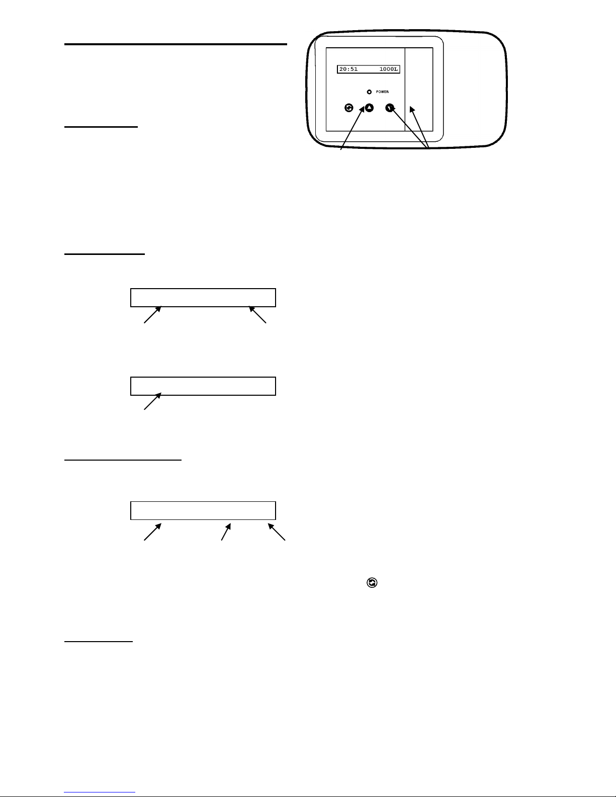
scroll button up / down buttons
to advance to adjust the
through the value of the
parameters parameter
The Electronic Timer
8:00 AM 1000GL
Regen 67 Cyc2:45
2:00 AM REGEN
Basic features
Control pad
The electronic timer uses a Printed Circuit Board (PCB),
equipped with a microprocessor and flash memory. All
programming is done by use of the 3-button control pad
with LCD-display.
Service mode
In service mode the display shows the time of day and remaining capacity:
time of day remaining capacity
When the remaining capacity equals the reserve capacity, the display will show the time of day and the indication
“REGEN”, indicating that a delayed regeneration will be started at the programmed time of regeneration:
time of day
Regeneration mode
In regeneration mode the display shows the total remaining regeneration time, the actual regeneration cycle and the
remaining cycle time:
total remaining actual regen. remaining
regen. time cycle cycle time
The control valve can be reset to service mode at any time by pushing the button, thus manually advancing it
through the regeneration cycles.
Flow meter
In service mode the display shows the time of day and remaining capacity; the remaining capacity counter counts back
per unit, i.e. per litre or gallon. By opening a faucet after the unit, the correct functioning of the flow meter can be
checked by means of this counter.
Page 6
4
Power failure
Service Required
In the event of a power failure, the program remains stored in the flash memory, while an incorporated SuperCap
(capacitor) will maintain the correct time of day during a period of several hours; consequently, in case of prolonged
power failure, the time of day might not be maintained; if this happens, the time of day indication will, when the power
supply is re-established, be flashing, indicating that the time of day needs to be set; refer to “Programming instructions
for the End-User level” to set the correct time of day.
When a power failure occurs when the holiday mode is activated, it will remain activated when power is restored,
providing that the incorporated SuperCap has maintained the time of day over the entire duration of the power failure.
When the power failure occurs during the execution of an automatic regeneration, the control valve will remain in it’s
last position; when the power supply is re-established, the control valve will return to the service position, stay there for
60 sec. and restart a complete regeneration from the beginning.
Timer failure
In the event of a timer failure, the display will show the message:
In such case, entering one of the programming levels can possibly solve the problem. However if the problem persists,
professional service is required.
Programming
!!! ATTENTION
During programming, it is necessary to enter the desired change within 5 minutes. Otherwise the microprocessor will
automatically break off the programming and return to the service mode, while all possibly entered changes to the
program are lost. If this occurs, it will be necessary to re-initiate the programming process.
All programming parameters are grouped into different user-specific levels (end-user / installer / OEM / factory).
The end-user level is accessible freely, no specific access code is required; in order to access one of the 3 other
specific levels, the proper access code, i.e. key sequence, needs to be entered.
In the programming modes, a flashing indication implicates that this parameter can be adjusted by pushing the
button or button; in this technical manual this is indicated by means of an italic font.
Page 7
5
Programming instructions for the End-User level
Set 8:00 AM
Regen in 10 sec
Regen at 2:00 AM
Set 8:00 AM
Holiday
OFF
Holiday
ON
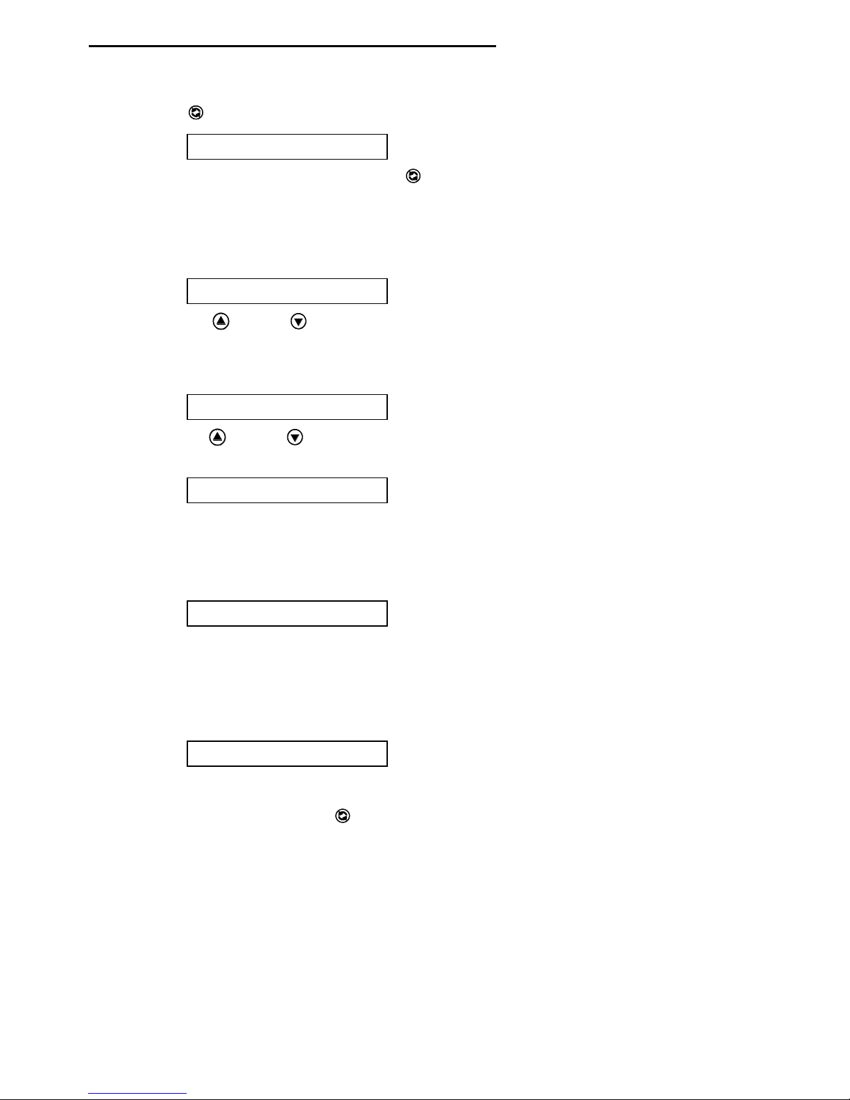
1. Accessing the End-User level:
Make sure that the control valve is in the service mode.
Push the button; the display will show:
You are now in the End-User level; use the button to advance through the different programming
parameters.
2. Available programming parameters:
1) Time of day setting:
The display will show:
Push the button or button to set the correct time of day.
2) Holiday mode:
The display will show:
Push the button or button to activate the holiday mode, meaning the unit will not regenerate; the
3) Immediate regeneration mode:
4) Delayed regeneration mode (not available in case regen. type is set to “Immediate” in the OEM level):
display will show:
The holiday mode is cancelled when a flow rate greater than 6 L/min is measured or when one of the
buttons is pushed. In either of these cases the unit will start an immediate regeneration.
The display will show:
If the control valve is left in this position, the countdown timer will countdown to 0 sec and start a
regeneration.
To cancel this mode, push the button before the countdown timer has reached 0 sec.
The display will show:
If the control valve is left in this position, the unit will perform regeneration at the programmed time of
regeneration.
To cancel this mode, push the button.
Page 8

6
Diagnostics level
Regen Xdays ago
Exit
1. Accessing the Diagnostics level:
Make sure that the control valve is in the service mode.
Push the button and hold it for 5 sec until the display shows:
You are now in the Diagnostics level; use the button to advance through the different diagnostics
parameters.
2. Exiting the Diagnostics level:
If no button is pushed within a time frame of 5 minutes, the microprocessor will exit the diagnostics level end
return to the service mode.
Push the button until the display shows:
Push the button or button to exit the Diagnostics level.
3. Available diagnostic parameters (depending on the Installer and OEM programming, some of the following
parameters might not be available (*)):
Regen X days ago: display shows number of days since last regeneration of the unit.
In Srvc: displays show many days the unit has been in service.
# of Regens: display shows the number of regenerations that have taken place since installation.
TotVol (*): display shows the total water usage through the unit since installation.
LastRg@ (*): display shows the water usage at the moment of the last regeneration.
PeakFlow (*): display shows the peak flow rate since the last regeneration; this parameter resets back to 0 after
every regeneration – metric only. In English, shows “Flow Rate”.
AvgVol (*): display shows the average daily water usage.
Capacity/System (*): if the control valve is programmed for Volume, the display shows the setting of the
volume of softened water between regenerations; when the control valve is programmed for Hardness, the
display shows the setting of the total softening capacity between regenerations.
WaterHard (*): display shows the setting of the water hardness.
Rsrv (*): display shows whether the control is programmed for fixed or variable reserve; in case of fixed
reserve it will also show the reserve capacity setting.
Regen @: display shows the setting of the time of regeneration.
Override: display shows “OFF” or the setting of the number of days between regenerations.
Cycle 1: display shows the setting of the length of the backwash cycle.
Cycle 2: display shows the setting of the length of the brine/slow rinse cycle.
Cycle 3: display shows the setting of the length of the fast rinse/brine refill cycle.
Units: display shows the setting of the mode of measurement.
Flow Meter Type: display shows the flow meter type setting.
Capacity (*): display shows whether the control is programmed for Volume or Hardness setting.
Regen: display shows the regeneration type setting.
Valve Type: display shows the valve type setting.
MP Resets: display shows the number of resets of the microprocessor (for factory purpose only).
Memory Reset: display shows the number of corrupt memory start-ups (for factory purpose only).
4000 VTL REV X: display shows the software version (for factory purpose only).
Page 9

7
Fast program check
Regen in 10 sec
Regen X Cyc1:Y
Regen X Cyc2:Y
Regen X Cyc3:Y
8:00 AM 1000GL
When you want to check if the unit is operating correctly, proceed as follows:
1. Plug unit into power supply.
2. Open water supply to valve.
3. Push the button until the display shows:
4. Leave the control valve in this position; the countdown timer will countdown to 0 sec and start a regeneration.
5. The motor will start and the display will show:
total remaining backwash remaining
regen. time cycle cycle time
6. You can push the button again to switch the motor to full speed, which will shorten the transfer time needed by
the control valve to reach the next position.
7. The motor will move the control valve into backwash position; check the drain line for clear flow.
8. Push the button; the motor will start and the display will show:
total remaining brine/slow rinse remaining
regen. time cycle cycle time
9. The motor will move the control valve into brine/slow rinse position; check brine draw by listening or feeling for
suction.
10. Push the button; the motor will start and the display will show:
total remaining fast rinse/brine remaining
regen. time refill cycle cycle time
11. The motor will move the control valve into fast rinse/brine refill position; check the drain line for flow.
12. Push the button; the motor will start and the display will show:
13. The motor will move the control valve back into service position.
Page 10

8
Parts Replacement
!!! BEFORE SERVICING:
MAKE SURE THE CONTROL VALVE IS IN SERVICE POSITION
DISCONNECT ALL ELECTRICAL POWER TO THE UNIT
BYPASS OR DISCONNECT THE WATER SUPPLY
RELIEV THE WATER PRESSURE
Printed Circuit Board
1. Loosen the 3 front cover screws and remove the front cover.
2. Disconnect all connectors from the PCB.
3. Remove the flat cable of the 3-button control pad from the push-in connection on the PCB.
4. Remove the screw holding the PCB in place.
5. Push aside the clip holding the PCB in place and remove the PCB.
6. Reverse the procedure for reassembly; refer to wiring diagram for proper lead connections.
Page 11

9
Drive motor
1. Remove the timer head assembly; refer to Parts Replacement “Timer head assembly”.
2. Loosen the 3 front cover screws and remove the front cover.
3. Disconnect the wire connector from the drive motor.
4. At the back of the back plate, remove the 2 screws holding the drive
motor assembly in place and remove the micro switch assembly and
drive motor.
5. Remove the retaining ring securing the worm and remove the worm
from the drive shaft.
6. Pull the drive shaft out of the drive motor.
7. Install the drive shaft in the drive motor, with the flat side on the
drive shaft pointing down (mark on the drive shaft pointing up (1)).
8. Install the worm on the drive shaft and install the retaining ring
securing the worm.
9. Put the micro switch assembly on the drive motor; make sure the
switch cam is in the service position (2).
10. Install the micro switch assembly and drive motor on the back plate
and secure it with the 2 screws.
11. Connect the wire connector on the drive motor; refer to wiring
diagram for proper connection.
12. It is now necessary to check the synchronization of valve body and
timer head; refer to Parts Replacement “Synchronizing valve body
and timer head”.
Injector
1. Remove the drain hose from the drain elbow.
2. Remove the 6 bolts and nuts holding the valve body and cover
together.
3. Lift the valve cover away from the valve body.
4. Remove the rotor assembly from the valve cover; the white
Teflon O-ring will remain in the valve cover.
5. Remove the seal plate from the valve body.
6. Remove the insert plate and gasket from the valve body.
7. Using a needle nose pliers grasp one side of the injector and
pull the injector straight out of the valve body.
8. Make sure the float valve is straight up into the float chamber
of the valve body.
9. Install the insert plate and gasket in the valve body.
10. Lightly lubricate the O-rings of the new injector with a soap
water solution.
11. Install the injector with one of the rectangular openings on the injector facing directly towards the centre of the valve
body; push the injector firmly down.
12. Install the seal disk in the valve body, with the green side facing up.
13. Install the rotor assembly into the valve body ensuring that the arrow
on the worm gear is pointing directly towards the second tooth on the
worm drive shaft (facing the front of the control valve); the 2 holes in
the rotor assembly should now be exactly aligned with the
corresponding holes in the seal disk.
14. Centre the PE washer on the worm gear.
15. Make sure the valve cover O-ring is clean and securely installed
around the raised rib on the valve cover.
16. Lower the valve cover straight down onto the valve body and press it
down firmly and evenly to seat the valve cover.
17. Install the 6 bolts and nuts and tighten them in a cross pattern.
18. Install the drain hose to the drain line fitting.
Page 12

10
Backwash flow control
1. Remove the drain hose from the drain elbow and remove the drain elbow.
2. Unscrew the backwash flow control using a 3/8” Allen wrench.
3. Reverse the procedure for reassembly.
Brine refill flow control
1. Remove the clip securing the refill elbow.
2. Remove the brine refill flow control from the refill elbow.
3. Reverse the procedure for reassembly.
Brine tee
1. Remove the brine line and brine refill tube from the brine tee.
2. Remove the brine tee by turning it counter clockwise.
3. Remove the O-ring, the retainer and check ball from the brine tee.
4. Reverse the procedure for reassembly.
Rotor assembly
1. Remove the drain hose from the drain elbow.
2. Remove the 6 bolts and nuts holding the valve body and cover together.
3. Lift the valve cover away from the valve body.
4. Remove the rotor assembly from the valve cover; the white Teflon O-ring will remain in the valve cover.
5. Inspect the rotor plate’s surface; it should be smooth and free of any circular grooves or scratches; replace if
necessary.
6. Install the rotor assembly into the valve body ensuring that the arrow
on the worm gear is pointing directly towards the second tooth on the
worm drive shaft (facing the front of the control valve); the 2 holes in
the rotor assembly should now be exactly aligned with the
corresponding holes in the seal disk.
7. Center the PVC sleeve on the worm gear.
8. Make sure the valve cover O-ring is clean and securely installed
around the raised rib on the valve cover.
9. Lower the valve cover straight down onto the valve body and press it
down firmly and evenly to seat the valve cover.
10. Install the 6 bolts and nuts and tighten them in a cross pattern.
11. Install the drain hose to the drain line fitting.
Seal disk
1. Remove the rotor assembly; refer to Parts Replacement “Rotor assembly”.
2. Remove the seal disk from the valve body.
3. Inspect the seal disk; make sure the raised ribs are intact; the green Teflon coating may be worn off of the ribs, but
this won’t affect the sealing performance of the seal disk; replace if necessary.
4. Use silicone base lubricant to lubricate the green side of the seal disk.
5. Install the seal disk in the valve body, with the green side facing up.
6. Reverse the procedure for reassembly; refer to Parts Replacement “Rotor Assembly”.
Page 13

11
Gasket
1. Remove the seal disk; refer to Parts Replacement “Seal disk”.
2. Remove the insert plate and gasket from the valve body
3. Inspect the insert plate; make sure the ribs are intact.
4. Using a needle nose pliers grasp one side of the injector and
pull the injector straight out of the valve body.
5. Clean the surface of the valve body.
6. Make sure the float valve is straight up into the float chamber
of the valve body.
7. Install the insert plate and gasket in the valve body.
8. Install the injector with one of the rectangular openings on the
injector facing directly towards the centre of the valve body;
push the injector firmly down.
9. Reverse the procedure for reassembly; refer to Parts
Replacement “Seal disk”.
Float valve
1. Remove the gasket; refer to Parts Replacement “Gasket”.
2. Remove the float valve straight out of the float valve chamber of the valve body.
3. Remove the spring from the float valves shaft.
4. Clean all sealing surfaces inside of the float chamber.
5. Install the spring inside of the float valves shaft.
6. Install the float valve straight up into the float chamber of the valve body.
7. Reverse the procedure for reassembly; refer to Parts Replacement “Gasket”.
Timer head assembly
1. Remove the screw holding the flow meter sensor in place and remove the flow meter sensor.
2. Remove the 2 back plate mount screws and take away the timer head assembly.
3. Reverse the procedure for reassembly.
Worm drive shaft
1. Remove the timer head assembly; refer to Parts Replacement “Timer head assembly”.
2. Unscrew the packing gland nut.
3. Remove the packing gland nut/worm drive shaft from the valve body.
4. Separate the packing gland nut from the worm drive shaft.
5. Inspect the worm drive shaft; the threads should not be deformed or damaged; replace if necessary.
6. Install the worm drive shaft in the valve body, by turning it clockwise as far as possible.
7. Lubricate the O-rings of the worm drive shaft.
8. Install the packing gland nut over the worm drive shaft and screw it into the valve body.
9. Install the timer head assembly to the valve body and tighten the 2 back plate mount screws.
10. It is now necessary to check the synchronization of valve body and timer; refer to Parts Replacement “Synchronising
valve body and timer head”.
Page 14

12
Impeller
8:00 AM 1000GL
1. Remove the outlet from the control valve.
2. Depress snap head on bottom side of valve to remove sensor clip.
3. Use needle nose pliers to remove impeller hub to access impeller.
4. Reverse the procedure for reassembly.
Synchronizing valve body and timer head
To insure the proper operation of the control valve, valve body and timer head should be synchronized in the service
position. Proceed as follows:
Step 1: Timer head
1. Make sure that the control valve is in the service mode; if the control valve is in regeneration, push the
Step 2: Valve body
1. Remove the drain hose from the drain elbow.
2. Remove the 6 bolts and nuts holding the valve body and cover
3. Lift the valve cover away from the valve body.
4. Make sure the arrow on the worm gear is pointing directly towards
5. Make sure the valve cover O-ring is clean and securely installed around the raised rib on the valve cover.
6. Lower the valve cover straight down onto the valve body and press it down firmly and evenly to seat the valve cover.
7. Install the 6 bolts and nuts and tighten them in a cross pattern.
8. Install the drain hose to the drain line fitting.
button, thus manually advancing it through the regeneration cycles, until the display shows the time of day:
2. The flat side on the drive shaft should be pointing down (mark
on the drive shaft pointing up (1)); if this is not the case: refer
to Parts Replacement “Drive motor”.
together.
the second tooth on the worm drive shaft (facing the front of the
control valve) (2); the 2 holes in the rotor assembly should now be
exactly aligned with the corresponding holes in the seal disk.
Page 15

13
Troubleshooting
Cause
Solution
1. Open or defective bypass
1. Close or verify bypass
2. Control valve in regeneration
2. /
3. Leak between rotor and seal disk
3. Verify or replace rotor and seal disk
4. Loss of resin
4. Refer to problem “Loss of resin”
5. Change in raw water hardness
5. Adjust programming accordingly
6. Valve body and timer out of
synchronization
6. Synchronize valve body and timer
7. Unit fails to regenerate
7. Refer to problem “Unit fails to regenerate”
8. Control valve fails to draw brine
8. Refer to problem “Control valve fails to draw brine”
9. Decreasing exchange capacity of resin
9. Clean or replace resin bed
10. No salt in brine tank
10. Add salt
11. Leak at riser tube
11. Verify that riser tube is seated correctly and is not cracked
Cause
Solution
1. Faulty electrical supply
1. Verify electrical service (fuse, transfo,)
2. Defective flow meter
2. Clean and/or replace flow meter
3. Defective PCB
3. Replace PCB
4. Defective drive motor
4. Replace drive motor
5. Defective micro switch
5. Replace micro switches
Cause
Solution
1. Low inlet pressure
1. Verify operating pressure; must exceed 1,4 bar
2. Plugged injector
2. Clean injector
3. Restricted drain line
3. Verify drain line for kinks, verify backwash flow control to
insure it is free of debris
4. Restricted brine line
4. Verify brine line for kinks or restrictions
5. Leak in brine line
5. Verify brine line and connections for air leakage
6. Not enough water in brine tank
6. Refer to problem “Control valve fails to refill brine tank”
Cause
Solution
1. Defective or shorted micro switch
1. Replace micro switches
Hard (untreated) water to service
Unit fails to regenerate
Control valve fails to draw brine
Control valve cycles continuously
Page 16

14
Excessive water in brine tank
Cause
Solution
1. Control valve fails to draw brine
1. Refer to problem “Control valve fails to draw brine”
2. Improper fast rinse/brine refill time
setting
2. Verify that fast rinse/brine refill time corresponds to the proper
salt level and amount of resin
3. Improper or missing brine refill flow
control
3. Verify that flow control is installed and properly sized
4. Leak between rotor and seal disk
4. Verify or replace rotor and seal disk
Cause
Solution
1. Improper fast rinse/brine refill time
setting
1. Verify that fast rinse/brine refill time corresponds to salt level
and amount of resin
2. Improper refill flow control
2. Verify that flow control is properly sized
3. Plugged refill flow control
3. Verify that flow control is free of debris
Cause
Solution
1. Excessive water in brine tank
1. Refer to problem “Excessive water in brine tank”
2. Unit regenerates too frequently
2. Verify capacity, reserve capacity and day setting
Cause
Solution
1. Excessive water in brine tank
1. Refer to problem “Excessive water in brine tank”
2. Injector undersized
2. Verify injector selection
3. Improper brine/slow rinse time setting
3. Verify that brine/slow rinse time corresponds to the proper salt
level and amount of resin
4. Improper fast rinse/brine refill time
setting
4. Verify that fast rinse time corresponds to the proper salt level and
amount of resin
Cause
Solution
1. Improper or missing backwash flow
control
1. Verify that flow control is installed and correctly sized
2. Lower and/or upper distributor
damaged
2. Replace distributor(s)
3. Leak between riser tube and upper
distributor
3. Verify that riser tube is seated correctly and is not cracked
Control valve fails to refill brine tank
Unit uses too much salt
Salt water to service
Loss of resin through drain line
Page 17

15
Loss of water pressure
Cause
Solution
1. Mineral or iron build-up in resin tank
1. Clean resin bed and control valve; increase regeneration
frequency
2. Plugged lower and/or upper distributor
2. Verify that distributors are free of debris
3. Crushed lower and/or upper distributor
3. Replace distributor(s)
Cause
Solution
1. Defective PCB
1. Replace PCB
2. Defective micro switch
2. Replace micro switches
3. Defective drive motor
3. Replace drive motor
4. Valve body and timer out of
synchronization
4. Synchronise valve body and timer
5. Leak between rotor and seal disk
5. Verify or replace rotor and seal disk
Drain flows continuously
Annual Maintenance
To assure the correct functioning of the control valve, the following items must be checked annually:
1. Clean out injector.
2. Clean brine refill flow control.
3. Clean backwash flow control.
4. Verify correct functioning of flow meter; clean impeller if necessary.
5. Verify programming of timer; re-program timer if necessary.
6. Verify correct execution of program (refer to “Fast program check” on pg. 16).
7. Verify min and max. pressure; install pressure reducer if necessary.
Page 18

16
Exploded Views & Part Numbers
Valve
Page 19

17
ITEM
PART NUMBER
DESCRIPTION
1
70793
Drain Fitting Elbow ¾” NPT to 1/2” Barb
2a
75050
Back Wash Flow Control 1.6 GPM
2b
75051
Back Wash Flow Control 1.8 GPM
2c
72174
Back Wash Flow Control 2.0 GPM
3
71070
Hex Bolt
4
71083
Valve Cover
5
70658
O-Ring Valve Cover
6
72327
Teflon Washer
7
70665
Teflon O-Ring
8
71089
Worm Gear
9
71088
Cam
10
70656
O-Ring Cam & Rotor
11
71132
Rotor Plate
12
71084
Seal Disc
13
71182
Insert Plate
14
71183
Gasket Insert Plate
15
71006
Spring Float
16
71127
Float Valve
17
70660
O-Ring Float
18
72558
Valve Body
19a
71063
Injector #1
19b
71066
Injector #4
20
70655
O-Ring Injector Lower
21
70664
O-Ring Injector Upper
22
71071
Nut Hex
23
71947
Spring Clip
24
71344
O-Ring Riser Adapter
25
71118
Riser Adapter
26
70662
O-Ring Riser Adapter
27
70663
O-Ring Tank
28
71010
Adapter Upper Basket
29
71512
Screw Upper Basket Adapter
30
71060
Worm Drive
31
70616
Teflon Washer
32
70666
O-Ring Worm Drive
33
70661
O-Ring Gland Nut
34
71069
Packing Gland Nut
35
71124
Brine Line Fitting Retainer
36
70667
O-Ring Brine Line Refill Elbow
37
71961
Check Ball Brine Refill Elbow
38
70984
Spring Check Ball
39
13490
Compression Nut 3/8
40
71184
Flow Washer Insert
41a
71728
Flow Control Refill 0.25 GPM
41b
70994
Flow Control Refill 0.50 GPM
42
75073
Check Tee Assy
43
72544
Impeller Assy L W/Bushing
44
72545
Hub Flow meter Assy
45
12625
Tube Support .375
46
13604
Tubing Black .375
47
72458
Flow Diffuser
Page 20

18
DIR Control Parts
Page 21

19
ITEM
PART
DESCRIPTION
1
72237
Flip Cover Front
2
72516
Label PCB
3
70968
PCB Switch
4
72254
Flip Cover Rear
5
70618
Screw PCB
6
72500
PCB 2 Line Blue
7
72519
Sensor Cable
8
70971
Power Cable
9
72451
Switch Assy
10
70970
Motor Cable
11
70668
Retaining Ring
12
71075
Worm Gear
13
71656
Motor
14
70720
Motor Shaft
15
70965
Cam
16
70622
Screw 2-28x3/4 Self Thread
17
72138
Transformer
18
72497
Valve Cover Rear Flip
19
71185
Switch Bracket
20
71106
Hub Gear
21
70625
Screw 6-32 x 7/16
22
72134
Strain Relief Sensor Cable
23
71497
Screw 10-16 x 1
24
70618
Screw Cover
25
70312
Strain Relief Power Cable
 Loading...