

Page 1
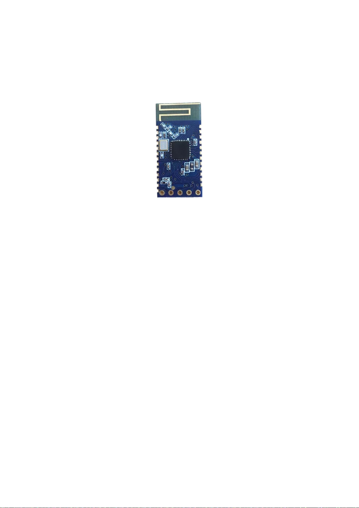
Super Bluetooth Module
JDY-24M Bluetooth Module Manual
Page 2

JDY-24M SuperBLE Bluetooth Module
Version
Versi
on
V1.3 2019-11-18 Release version
V1.4 2019-12-13
V1.5 2020-01-09
Date Description
Update:
1、V1.3 has been updated. The slave BUH in AT+ROLE0 mode can not
be searched when sending AT+INQ in AT+ROLE1 mode.
2、Updated. In mesh mode, APP is connected to the current slave and
cannot send unicast data bug to the current slave.
3、Added the function of sending AT+DISC and AT+STAT instructions
without PWRC pull down in the connection state. Only these two
instructions are valid in the connection state.
4、Updated. When the APP connects to the current module, it sends
MESH broadcast data. The BUG of current device has a different data
format from other devices.
According to the requirements of the switch panel manufacturer, the
following functions are specially added (the previous functions are
completely unchanged)
1、It added the function that users can learn the press and output IO
freely when the switch panel is applied. If without APP configuration, the
users can learn freely through key. The advantages of switch learning are
that one key can be learned by multiple output IO relays, or one output IO
relay can be learned by multiple keys. The key and output IO support
one-to-many, many-to-many, many-to-one learning.
2、In the network state, the newly added instruction AT+SUBTYPE is
used to distinguish whether the output IO of the current module OUTPUT
is controlled by itself and the target, or only by the target device
3、Newly added instruction AT+LEARN for switch learning function.
The newly added instruction AT+LEAVAL is used to query the learning
parameters of the current output IO, or set the learning parameters of the
output IO directly through this instruction.
V1.6 2020-02-29
The following BUG is modified:
The BUG is that unicast data cannot be sent to the xxFF address device in
the network state.
The following functions are added (the previous functions are completely
unchanged)
1、AT+ROLE7 master-slave working mode was added. The master
supports connection of four slaves at the same time, or mixed working of
the master and the slave at the same time (the master connects the slave
while the slave is connected by the mobile phone, work at the same time).
2、AT+DEVCLSS, AT+KLABEL, AT+KLTIME, AT+KLRSSI and other
new function instructions have been added.
Page 3

JDY-24M Super BLE Bluetooth Module
3、AT+ROLE8 key label detection mode is added.
4、Added key label detection function (when a key label is close to
JDY-24M, JDY-24M outputs IO output action level).
5、Add the function that in the switch panel learn mode , long press
PWRC pin to clear the learning code.
6、The function of the switch panel is optimized, which is more user
friendly.
After JDY-24M is upgraded to V1.6, there will be no major upgrade, and V1.6 will be the final
version.
The terminal PWM node, LED light node, relay node, touch switch node, sensor and other node
products will be launched later with JDY-24M as the center. These nodes are low-cost nodes.
Ⅰ. Product introduction
JDY-24M super Bluetooth function supports master-slave transparent transmission, iBeacon,
BLE probe, iBeacon detection, and MESH network. The maximum number of MESH network
supports 65280 device network. Multi-hop wireless anti-collision technology is adopted. The
network communication speed supports 50ms to send 16 byte data. The single module supports
routing node and terminal node. The routing node supports data relay (low power consumption is
not supported). The terminal node supports low power consumption (automatic sleep after key
wake-up and data sending), JDY-24M network generally only needs to be configured with
network NETID and short address, and the module will automatically network. When the network
module communicates with APP, it is equivalent to transparent transmission, which greatly
convenient for users to develop APP compatible with old products APP.
Ⅱ. Product characteristics
1:Support data transparent transmission with mobile phone (IOS, Android) APP (working current
about 1mA)
2:Support module and module master slave high speed transparent transmission
3:Support iBeacon function (ultra-low power consumption)
4:Support iBeacon probe function
5:Support BLE Bluetooth probe function
6: Multi-connected slave mode is supported. Multi-connected slave can connect with multiple
mobile phones and transparent transmission at the same time.
7:Support Bluetooth MESH network (Network serial port data communication, output IO control,
input key control)
8:MESH network data sending supports response and no response communication
9:Network remote control
10: Multi-connected master-slave mixed connection (the master is connected to the slave at the
same time, and the slave is connected to the mobile phone at the same time, and work at the same
time)
Page 4

JDY-24M Super BLE Bluetooth Module
. Product application scope
Ⅲ
1:Bluetooth network LED (one-to-many, many-to-one, mobile phone or remote controller control,
many-to-many control)
2:Bluetooth network serial port communication application (one-to-many, many-to-one, mobile
phone or remote controller control, many-to-many control)
3:Network panel switch, 86 switch (ultra-low power consumption)
4:Network smart home application (switch, relay,curtain) control
5:Network sensor application
6:WIFI network gateway application
7:Zigbee network application
8:Mobile network control application
9:Key label
. Technical specifications:
Ⅳ
Type Specification parameter
Working voltage 1.9 – 3.6V
Working temperature -40 - 85°C
Maximum transmitting power +4dbm
Communication distance 80m
Bluetooth version BLE5.0
Antenna PCB board antenna
Antenna gain -3dbi
Receiving sensitivity -96dbm
SMT welding temperature
Communication interface UART
Module size 27mm * 12.88 *1.6
Communication speed between slave and
APP
MESH communication speed 50ms send 16byte
Average
current
Wake up (transparent
transmission) current in non
MESH mode
Light sleep of slave with
broadcast in non MESH mode
Wake up communication current
in MESH mode
Sleep current in MESH mode 3uA
Within 200uA (related to broadcasting
<260℃
8k(byte/s)
About 1mA
interval)
About 4mA
Deep Sleep Mode 3uA
Page 5

JDY-24M Super BLE Bluetooth Module
. Factory default configuration:
Ⅴ
No. Function Parameter ATinstructions
1 Baud rate 9600 AT+BAUD4
2 Module short address Last 2 bytes of
MAC address
3 Network ID 1189 AT+NETID1189
4 K1 target short address FFFF AT+KEY1,FFFF,1,1
5 K2 target short address FFFF AT+KEY2,FFFF,2,1
6 K3 target short address FFFF AT+KEY3,FFFF,3,1
7 K4 target short address FFFF AT+KEY4,FFFF,4,1
8 K5 target short address FFFF AT+KEY5,FFFF,5,1
9 APP connection password
switch
10 APP connection password 1234 AT+PIN1234
11 Broadcast name JDY-24M AT+NAMEJDY-24M
12 Router node 0 AT+MCLSS0
13 Transmitting power 4 AT+POWR4
14 OUTPUT and INPUT
unrelated
15 Learn mode off 0 AT+LEARN0
Special instruction: V1.5 default that factory setting of K1 to K5 is not 0, so the customer is misled that all key
values are the same.
Example: If it needs K1 to control the OUTPUT1 level of all devices in the network, use the default parameters.
If it needs K1 to control only the OUTPUT1 level of 0008 target address, it is required to set K1 target
short address to 0008, complete instruction (AT+KEY1,0008,1,1)
OFF AT+TYPE0
0 AT+SUBTYPE0
Of course, K1 may not only control IO of the target device OUTPUT1
Example: K1 control target 0008 device OUTPUT2 level, complete instruction (AT+KEY1,0008,2,1)
If you need to synchronize the OUTPUT of the current device with the target device level of the KEY button, you
need to open this command: AT+SUBTYPE1
When the SUBTYPE is set to 1, the OUTPUT pin of the current device will be synchronized with the remote
device level controlled by the KEY button,
For example, when KEY1 is pressed, its own OUTPUT1 will also output the level, and the remote device
OUTPUT pin will also output the level. KEY2, KEY3, KEY4 and KEY5 will also be synchronized with its own
OUTPUT2, OUTPUT3, OUTPUT4 and OUTPUT5.
The default value of SUBTYPE is 0. The function is that the OUTPUT pin level is not associated with the output
level of the target device of the current KEY. Both OUTPUT and KEY are independent functions. KEY can control
the target device and OUTPUT can also be controlled by the remote device. Both are completely independent.
Page 6

JDY-24M Super BLE Bluetooth Module
TwoJDY-24M devices, one as a Learner and the other as a Code sender
The following is the function description of KEY and OUTPUT pin learning. In the learn mode, the parameters
configured by AT+KEY instruction are invalid. Only by learning or AT+LEAVAL can the parameters configured
by KEY button be valid.
1. Learn mode requires sending AT+LEARN1 instruction to open
2. It needs to associate OUTPUT with KEY, and send AT+SUBTYPE1 to open
After the above configuration, the KEY button and the OUTPUT pin of the remote device can be freely configured
through learning.
Method 1: AT instruction configuration
Example 1: Remote 0008 device KEY1 controls the OUTPUT1 and OUTPUT2 levels of the current device at
the same time
Current device sends instruction: AT+LEAVAL1,1,0008
AT+LEAVAL2,1,0008
Example 2: Remote 0008 device KEY2 controls the current device's OUTPUT5 level
Current device sends instruction: AT+LEAVAL5,2,0008
Method 2: Key Learning
1.Enter Learner mode: Double-click the PWRC pin, and the STAT light will flash slowly, and the LED light of the
ALED pin will be off to indicate that it has entered the Learner. In the learning state, if the OUTPUT pin does not
learn the key value, it will flash once a second. When the code sent by the Code sender is received, it will be
always on, indicating that the key value has been learned. When the KEY1-KEY5 pin of Learner is not pressed in
the learning state, it means that the learned key value of Learner OUTPUT1 to OUTPUT5 corresponds to the
KEY1 to KEY5 of Code sender, that is to say, Learner OUTPUT1 can only be controlled by the KEY1 of Code
sender, and of course, it also supports free learning.
Free learning method:
Example 1: The binding method of OUTPUT1 of Learner to KEY5 of Code sender:
Double-click the PWRC pin of Learner to enter the learn mode, and then press the KEY1 pin of
Learner to enter the learning state of Learner OUTPUT1, so that Learner OUTPUT1 can freely learn the key
values of Code sender KEY1 to KEY5. Press Code sender KEY5, and Learner OUTPUT1 will learn the KEY5
value of Code sender, so that Code sender KEy5 will be able to control the OUTPUT1 pin level of Learner.
2. Enter Code sender mode: Click PWRC pin, and the LED light of STAT pin off, and the LED light of ALED pin
flashes slowly, indicating that it has entered Code sender. Then press KEY1-KEY5, and Learner will learn the
key value sent by Code sender.
Quit Learner mode: Double-click the PWRC pin, and the ALED light will flash quickly (once a second).
Only after quitting the learn mode can the learned parameters work normally.
3. Quit Code sender mode: Click the PWRC pin, and the ALED pin flashes quickly( once a second). The
KEY1-KEY5 will take effect only after quitting the Code sender mode.
In particular, the mode can be distinguished by LED flashing:
Learner: The LED light of the STAT pin flashes slowly, and the LED light of the LEED pin is off, indicating that
Page 7
JDY-24M Super BLE Bluetooth Module
it enters the Learner mode. In the Learner mode, the OUTPUT pin flashes, indicating that the pin is in the
learning state, and if it light constantly means the code has been learned.
Code sender: The LED light of STAT pin is off, and the ALED pin flashes slowly, indicating that it has entered
the Code sender mode. In the Code sender mode, press the INPUT button, and the corresponding OUTPUT
will be high level.
Normal work:LED of ALED pin flashes quickly(once a second), if there is a central machine, the
STATpin is on constantly, indicating normal work.
Key learning is generally used in the case of no APP or serial port configuration. If there is APP or
serial port configuration, it is easier to use.
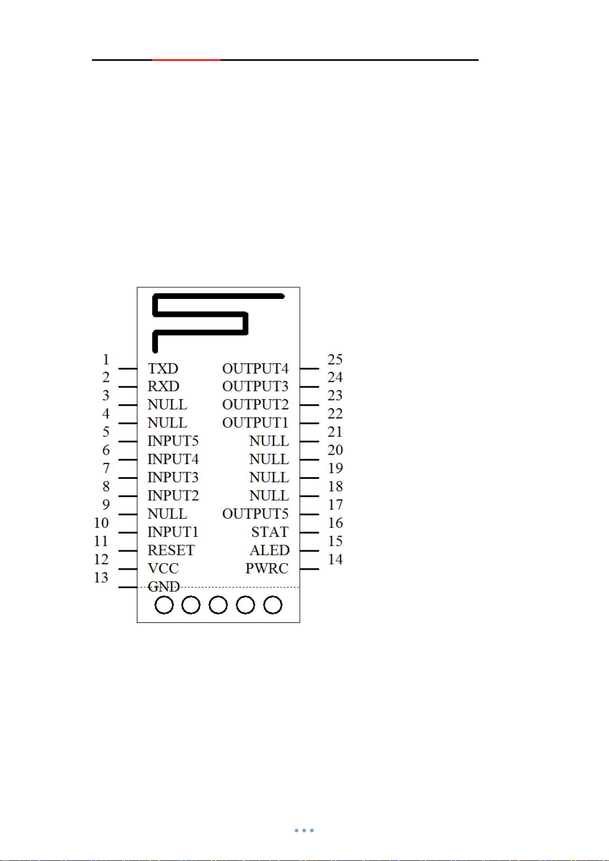
. Module pin definition
Ⅵ
Note: The general transport transmission application only needs to connect 4 pins of VCC, GND,
RXD and TXD.
Page 8

JDY-24M Super BLE Bluetooth Module
. Pin function description
Ⅶ
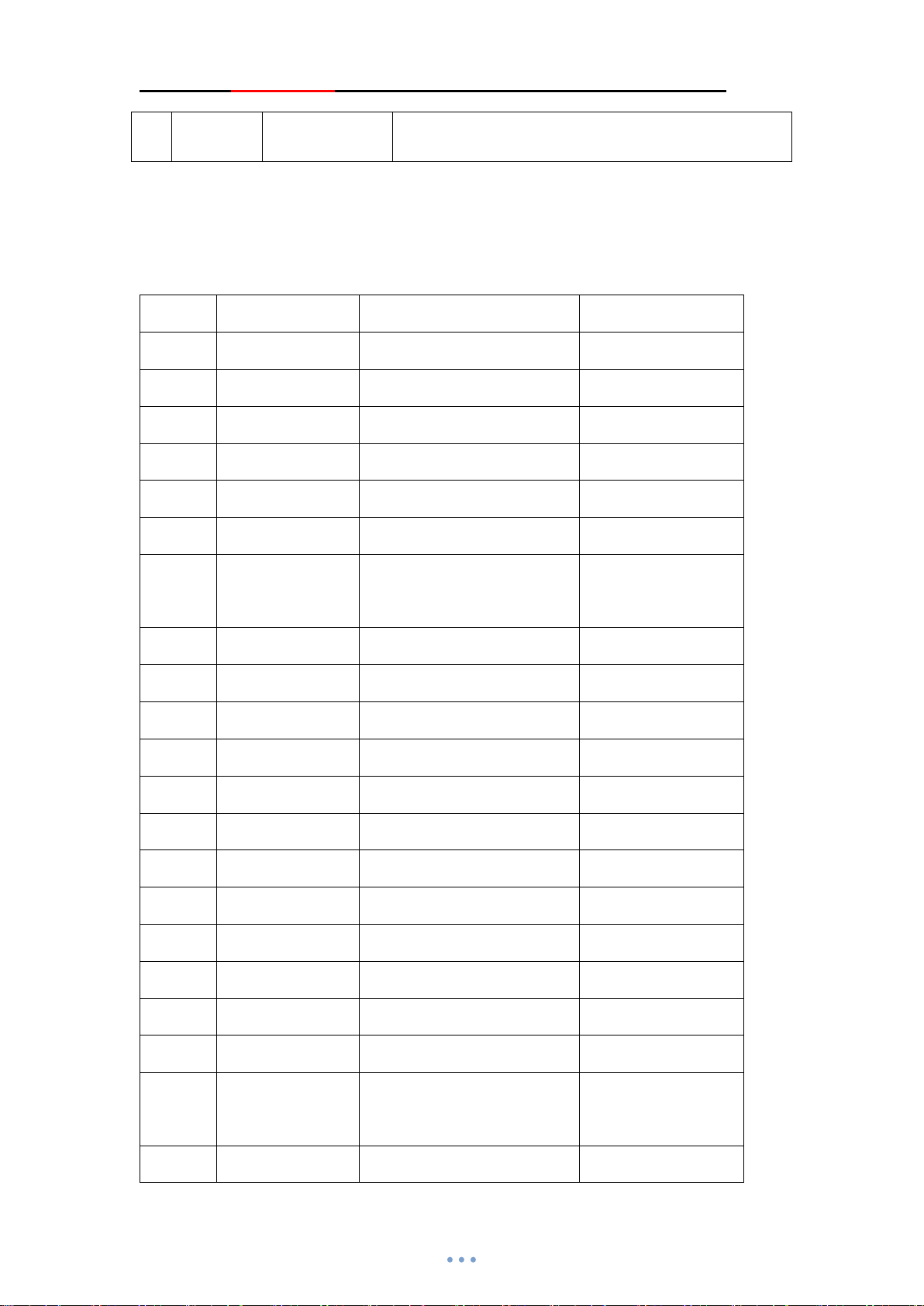
Pin Definition Function Description
1 TXD Serial port Serial output, the level is TTL level
2 RXD Serial port Serial input, the level is TTL level
3 NULL Null 4 NULL Null 5 KEY5 Input 5 In mesh mode, press the key to control the IO level of the
specified device
6 KEY4 Input 4 In mesh mode, press the key to control the IO level of the
specified device
7 KEY3 Input 3 In mesh mode, press the key to control the IO level of the
specified device
8 KEY2 Input 2 In mesh mode, press the key to control the IO level of the
specified device
9 NULL Null -
10 KEY1 Input 1 In mesh mode, press the key to control the IO level of the
specified device
11 RESET Reset Low level reset, high level working (high level if
suspended)
12 VCC Power Supply Supply(1.8-3.6V)
13 GND GND Power ground
14 PWRC Sleep wake pin Support PWRC pin wake-up in deep sleep state, and AT
instruction sending is supported when the connection
status is pulled down
15 ALED Broadcast LED
indication
16 STAT Connection
status
17 OUTPUT5 Output 5 Default low level, support serial instruction control and
18 NULL Null 19 NULL Null 20 NULL Null 21 NULL Null 22 OUTPUT1 Output 1 Default low level, support serial instruction control and
23 OUTPUT2 Output 2 Default low level, support serial instruction control and
24 OUTPUT3 Output 3 Default low level, support serial instruction control and
In non mesh mode (flash if not connected, light on after
connection)
In non mesh mode, low level if not connected, high level
after connection
In mesh mode (output high level if connect to network
successfully, if not, output low level)
input KEY pin control in network state
input KEY pin control in network state
input KEY pin control in network state
input KEY pin control in network state
Page 9
JDY-24M Super BLE Bluetooth Module
25 OUTPUT4 Output 4 Default low level, support serial instruction control and
input KEY pin control in network state
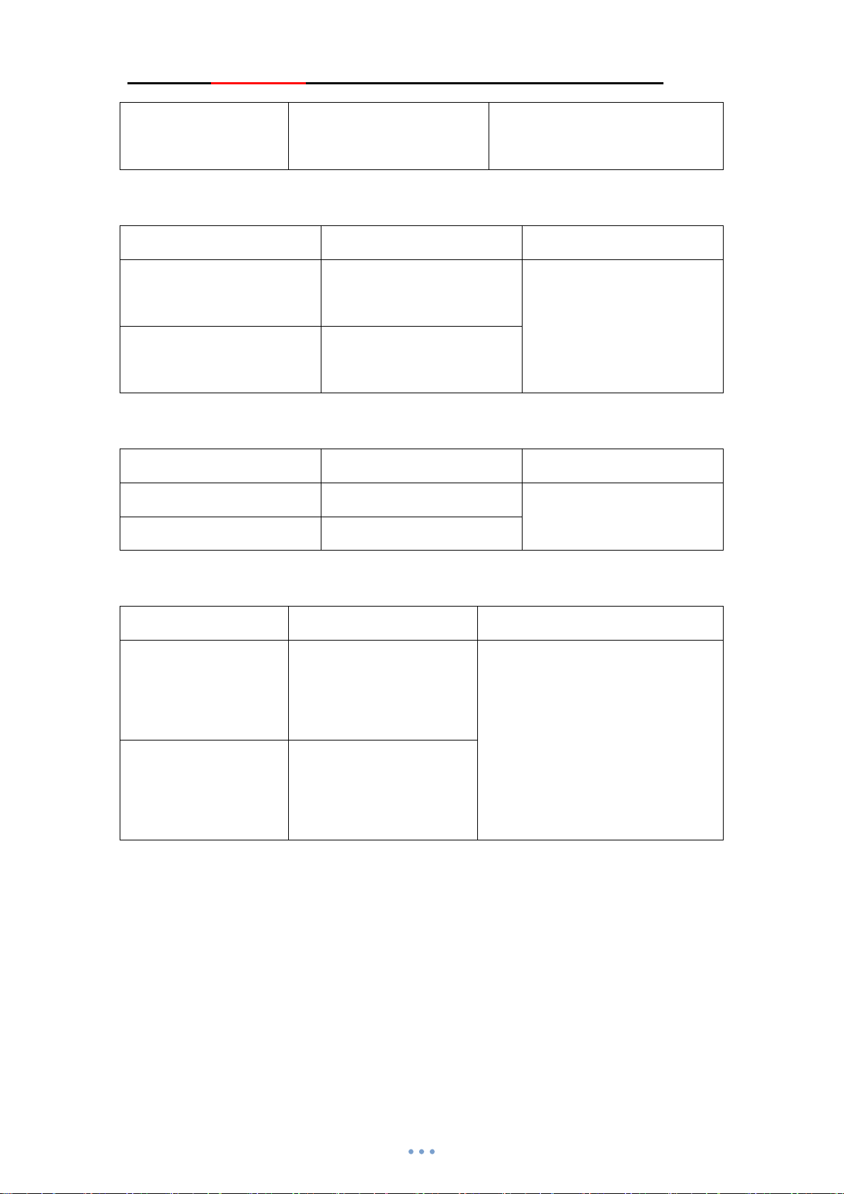
Ⅷ. Serial port AT instruction set
AT instruction sent by JDY-24M module serial port must add \r\n
No. Instruction Function Default
1 AT Test instruction -
2 AT+RESET Reset -
3 AT+VERSION Firmware version -
4 AT+LADDR Read MAC address -
5 AT+NAME Broadcast name read and write JDY-24M
6 AT+PIN Connection password setting 1234
7 AT+TYPE Whether to open password
connection mode
8 AT+BAUD Baud rate 115200
9 AT+DISC Disconnect -
10 AT+STAT Read connection status 0
11 AT+STARTEN Power on sleep setting 1
12 AT+ADVIN Broadcast interval 1
13 AT+POWR Transmitting power 3
14 AT+ROLE Working mode setting 0
15 AT+SLEEP Sleep instruction -
16 AT+DEFAULT Restore factory configuration -
17 AT+INQ Master search slave broadcast -
0
18 AT+STOP Stop broadcasting -
19 AT+CONN Connect scan list ID number -
20 AT+CONA Instruction MAC address
connection
21 AT+BAND Bind slave MAC address -
-
Page 10

JDY-24M Super BLE Bluetooth Module
22 AT+CLRBAND Clear binding -
23 AT+SRBAND Connect the strongest signal
slave nearby
24 AT+MESH MESH sends data -
25 AT+KEY Key parameter configuration -
26 AT+NETID Network ID number
configuration
27 AT+MADDR Network short address Last two digits of
28 AT+MCLSS Type of network device 0(Router)
29 AT+FRIEND Add private friend MAC
address
30 AT+CLRFRIEND Clear friend
31 AT+FRTYPE Friend type 0
-
1189
MAC address
000000000000
32 AT+IBUUID UUID configuration of
iBeacon
33 AT+MAJOR MAJOR configuration of
iBeacon
34 AT+MINOR MINOR configuration of
iBeacon
35 AT+IBSING SING configuration of
iBeacon
36 AT+ENLOG Serial port output status switch 1(On)
37 AT+DATA Data instructions sent by slave
multiple connections
38 AT+CUIO Serial port setting current
module output IO level
000A
0007
39 AT+TGIO Master controls the output IO
level of slave when the master
Page 11

JDY-24M Super BLE Bluetooth Module
communicates
40 AT+FUNC Master sets slave wireless
parameters
41 AT+SUBTYPE Subtype (routing mode is
valid)
42 AT+LEARN Learn switch 0
43 AT+LEAVAL Output IO learn parameters 0,0,0000
44 AT+DEVCLSS For one key connection of the
master to the strongest signal
slave nearby
45 AT+KLABEL Add label address
(10 Tags supported)
46 AT+KLTIME Set label overtime time 3s
47 AT+KLRSSI Set label sensitivity
(For receiving range setting)
0,0,000000000000
0
0
99
1、Test instruction
Instruction Response Parameter
AT
2、Reset
Instruction Response Parameter
AT+RESET +OK NULL
3、Query - software version number
Instruction Response Parameter
AT+VERSION
4、Query - Bluetooth MAC address
Instruction Response Parameter
+OK
+VERSION=JDY-24M-V1.3
NULL
NULL
Page 12
JDY-24M Super BLE Bluetooth Module
AT+LADDR +LADDR=<Param> Param: MAC address hex character
string
5、Set/query - BLE broadcast name
Instruction Response Parameter
AT+NAME<Param> +OK Param:BLE broadcast name
Max:18 byte
AT+NAME +NAME=<Param>
6、Set/query - BLE Bluetooth pairing password
Instruction Response Parameter
AT+PIN<Param>
AT+PIN
7、Set/query - BLE Bluetooth password connection mode
Instruction Response Parameter
AT+TYPE<Param> +OK
+OK
+PIN=<Param>
Default broadcast name:
JDY-24M
Param:4 bit password
Default PIN:1234
Param(0-2)
0:No password for connection
1:Password connection and not
AT+TYPE +TYPE=<Param>
Instruction: Not bind the password connection. The function is to input the password every time
the mobile phone is connected to the module.
Bind password connection. The function is that you only need to enter the password
once when connecting to the mobile phone, and the password is no longer needed for later
connection
Special instruction: When master slave transparent transmission, if the slave is configured
with a password connection, the master also needs to be configured with the same password
to connect, otherwise the master will not be able to connect to the slave.
binding
2:Password connection and binding
Default:0
Page 13

JDY-24M Super BLE Bluetooth Module
8、Set/query - Baud rate
Instruction Response Parameter
Param:(2 to 8)
AT+BAUD<Param> +OK
AT+BAUD +BAUD=<Param>
9、Disconnect
Instruction Response Parameter
AT+DISC +OK NULL
Instruction: In the connection state, send the AT+DISC instruction to disconnect the Bluetooth
connection by pulling down the PWRC pin.
2:2400
3:4800
4:9600
5:19200
6:38400
7:57600
8:115200
Default:8
10、Query - connection status
Instruction Response Parameter
Param(0-3)
AT+STAT +STAT=<Param>
Note: MESH status is valid only when there is a central machine in the network. In particular, when there is a
large number of networks, users are not recommended to open the central machine to cause network load.
0:Unconnected
1:Connected
2:Networked
3:Connected and
networked
Page 14

JDY-24M Super BLE Bluetooth Module
11、Set/query - Power on sleep or wake-up
Instruction Response Parameter
Param:(0-1)
AT+STARTEN<Para
m>
AT+STARTEN +STARTEN:<Param
>
Instruction: The power on sleep instruction can only be set in slave mode, other modes are invalid.
12、Set/query - Broadcast interval
Instruction Response Parameter
AT+ADVIN<Param> +OK
AT+ADVIN +ADVIN:<Param>
+OK
1: Power on wake-up, sleep can be controlled
through AT+SLEEP
0:Power on sleep, connect wake-up, disconnect
sleep
Default:1
Param:(0-9)
1:100ms
2:200ms
3:300ms
4:500ms
5:700ms
6:1000ms
7:1500ms
8:3000ms
9:60000ms
Default:1
13、Set/query - Transmitting power
Instruction Response Parameter
AT+POWR<Param> +OK
AT+POWR +POWR=<Param>
14、Set/query - Module working mode
Instruction Response Parameter
AT+ROLE<Param> OK
AT+ROLE +ROLE=<Param>
Param:(0-8)
0:-15dbm
1:-0dbm
2:2dbm
3:3dbm
4:4dbm
Default:4
Param:(0-8)
0:Transparent transmission of slave (APP,
Wechat, applet)
1:Master transparent transmission mode
2:BLE broadcast probe module
Page 15

JDY-24M Super BLE Bluetooth Module
3:iBeacon mode
4:iBeacon probe mode
5:MESH network mode
6:Multi-connected slave mode (supports 4
master connections)
7:Multi-connected master-slave (the master
supports to connect 4 slaves at the same time,
and the slave supports to connect 4 masters)
8:Key label detection mode (when the bound
label approaches, IO of JDY-24M will act)
Default:5
IBEACON probe mode output data format is as follows:
54 58 44 ea d8 f1 b5 a2 52 fd a5 06 93 a4 e2 4f b1 af cf c6 eb 07 64 78 25 00 0a 00 07 0d 0a
TX MAC RSSI iBeacon UUID Major Minor
End
15、Set/query - Sleep instruction
Instruction Response Parameter
AT+SLEEP<Param>
AT+SLEEP
+SLEEP:OK
1:Light sleep (with
Param:(1-2)
broadcast)
2:Deep sleep (without
broadcast)
Instruction: Only AT+SLEEP2 instruction is supported in MESH mode, and AT+SLEEP or AT+SLEEP1
instruction is supported in other modes.
16、Set - Restore factory configuration (Restore to factory default configuration parameters)
Instruction Response Parameter
AT+DEFAULT +OK NULL
17、Set - Master scan
Instruction Response Parameter
Param:(1-2)
AT+INQ<Param> OK
0:Search stops after 2 seconds
1:Search stops after 4 seconds
2:Search stops after 6 seconds
AT+INQ OK
3:Search stops after 8 seconds
4:Search stops after 16 seconds
Default:0 second
Example: +DEV:1=1893D711AB87,-82,JDY-08 MAC, RSSI and device name are returned when the
master scans the slave
Page 16
JDY-24M Super BLE Bluetooth Module
18、Set - Stop scanning
Instruction Response Parameter
AT+STOP OK NULL
If the user needs MCU to control the scan stop, it is generally recommended to set the search
device to 4 and the instruction is AT+INQ4 when scanning the device, so that the MCU can send
the instruction to stop the scan within this time, of course, it will automatically stop when the time
is up.
19、Search list connection
Instruction Response Parameter
AT+CONN <Param> OK Param:(0-7)
AT+CONN +CONN=<Param>
Example:AT+CONN1
20、Specify MAC address connection
Instruction Response Parameter
AT+CONA +CONN=<Param> Param: (MAC hex character string)
Example:AT+CONA112233445566
21、Set/query - Master binds MAC address
Instruction Response Parameter
AT+BAND<Param> OK Param: (MAC hex character string)
AT+BAND +BAND=<Param>
Example: AT+BAND112233445566
22、Set - Master unbind
Instruction Response Parameter
AT+CLRBAND OK NULL
23、Set - Master search the strongest signal slave nearby and bind and connect automatically
Instruction Response Parameter
AT+SRBAND OK NULL
24、Set - MESH sends data
Instruction Response Parameter
AT+MESH<Param> OK Param: (hex data)
Example: 41 54 2b 4d 45 53 48 00 ff ff 11 22 33 0d 0a
Instruction: The red part (41 54 2b 4d 45 53 48) is hexadecimal data of AT+MESH. The example function is to
send broadcast data to all devices in the target network. The broadcast data content is: 11 22 33
Page 17
JDY-24M Super BLE Bluetooth Module
As there are too many functions of MESH network, it will not be described in detail in this document. Please refer
to the document of Instructions for use of mesh. PDF.
25、Set/query - Key input pin function
Instruction Response Parameter
Param1:Indicates input IO number
AT+KEY<Param1>,<Param2>,<Param3>
<Param4>
AT+KEY<Param1>
,
+KEY=<Param1>
<Param2>
<Param3>,<Param4>
OK
,
(1-5)
Param2:Target address(0000 to ffff)
Param3:Target output IO number
(1-5)
,
Param4:Whether the target device
prints output (0-1) from the serial port
at the same time after receiving the
instruction, 0 means no serial port
output, 1 means simultaneous serial
port output
26、Set/query - MESH network ID number
Instruction Response Parameter
AT+NETID<Param1> OK Param1:(0000 to FFFF)
AT+NETID +NETID=<Param1>
Instruction: The ID number of the network within the same network must be the same, otherwise the network
cannot be established.
27、Set/query - MESH short address
Instruction Response Parameter
AT+MADDR<Param1> OK Param1:(0001 to FFFF)
AT+MADDR +MADDR=<Param1>
Instruction: The function of the short address in the network is the unique ID number of each device. The same
short address cannot appear in the same network. The short address is configured by AT instruction, and it can also
be automatically assigned. To automatically assign the address, you need to turn on the central machine, and
automatically assign the ID to the device that enters the network for the first time through the central machine. It is
generally recommended that the user configure the short address by ATinstruction himself.
28、Set/query - Mesh network device type
Instruction Response Parameter
AT+MCLSS<Param1> OK Param1:(0-1)
AT+MCLSS +MCLSS=<Param1>
0:Router (supports relaying)
1:Terminal device (without
relay function)
Instruction: Router supports data relay, not low power consumption
Page 18
JDY-24M Super BLE Bluetooth Module
The terminal settings should be applied to low-power consumption network device. The default is
power on sleep. Data will be sent after key wake-up and sleep will be immediately after sending.
29、Add / query - MESH friend MAC address
Response Parameter
OK Param1:(MAC address hex byte string)
+FRIEND=<Param1>
30、Clear -MESH friend MAC address
Instruction Response Parameter
AT+CLRFRIEND OK
31、Set/query - MESH friend type
Instruction Response Parameter
AT+FRTYPE<Param1> OK Param1:(0 or 1)
AT+FRTYPE +FRTYPE=<Param1>
Instruction: For private friend type, data can only be sent to the MAC address of the friend set by AT+RIEND. If
the MAC address is different from that of at + friend, data cannot be sent. Open friend type, you can specify all
friends around to send data one-to-one.
For the use of friend relation, please refer to the use instruction of MESH for details.
Default:000000000000
0:Private friend
1:Open friend
Default:0
32、Set/query - iBeacon UUID
Instruction Response Parameter
AT+IBUUID<Param> OK Param:Hex UUID
AT+IBUUID +IBUUID=<Param>
Example: 41 54 2B 49 42 55 55 49 44 FD A5 06 93 A4 E2 4F B1 AF CF C6 EB 07 64 78 25 0D 0A
Default:
FDA50693A4E24FB1AFCFC6EB076
47825
AT+IBUUID FDA50693A4E24FB1AFCFC6EB07647825 end mark
33、Set/query - iBeacon Major
Instruction Response Parameter
AT+MAJOR<Param> OK Param:(0000-FFFF)
AT+MAJOR + MAJOR=<Param>
If Major value is10008,AT instruction is: AT+MAJOR2718 2718 is 10008 hex data
Default:000A
34、Set/query - iBeacon Minor
Instruction Response Parameter
Page 19
JDY-24M Super BLE Bluetooth Module
AT+MINOR<Param> OK Param:(0000-FFFF)
AT+MINOR +MINOR=<Param>
If Minor value is 10180,ATinstruction is: AT+MINOR27C4 27C4 is 10180 hex data
35、Set/query - iBeacon IBSING
Instruction Response Parameter
AT+IBSING<Param> OK Param:(00-FF)
AT+IBSING +IBSING =<Param>
This parameter is applied to the check value of iBeacon signal at 1 meter.
36、Serial port status output enable set/query
Instruction Response Parameter
AT+ENLOG<Param> +OK Param:1 or 0
Default:0007
Default:40
AT+ENLOG +ENLOG=<Param>
1:Open serial port status
output
0:Close serial port status
output
Default:1
37、Data instruction sent by multi-connected slave
Instruction Response Parameter
+OK Param1:Indicates the master ID number,
AT+DATA<Param1><Param2
+DATA=<Param>
>
In the multi-connected status, when JDY-24M is connected by more than one master, data can be sent to the
specified master through this instruction.
Example: Such as sending AABBCCDDEEFF data to master 1
AT+DATA1AABBCCDDEEFF
values (1 to 4)
Param2:Indicates the data sent
38、Set/query - Output IO level of current module
Instruction Response Parameter
AT+CUIO<PA>,<PB>, +OK PA:Output IO number (1 to 5)
Page 20

JDY-24M Super BLE Bluetooth Module
PB:Indicates output level
P1:Indicates OUTPUT1 level
AT+CUIO +CUIO=<P1>,<P2
>,<P3>,<P4>,<P5>
,
P2:Indicates OUTPUT2 level
P3:Indicates OUTPUT3 level
P4:Indicates OUTPUT4 level
P5:Indicates OUTPUT5 level
Note: This instruction only controls the IO level of the current module through the serial port.
39、Master setting/query - Remote slave output IO level
Instruction Response Parameter
AT+TGIO<PA>,<PB>, +OK PA:Output IO number (1 to 5)
PB:Indicates output level
P1:Indicates OUTPUT1 level
AT+TGIO +TGIO=<P1>,<P2
>,<P3>,<P4>,<P5>
P2:Indicates OUTPUT2 level
P3:Indicates OUTPUT3 level
,
P4:Indicates OUTPUT4 level
P5:Indicates OUTPUT5 level
Note: This instruction is the master controls the slave level after the master-slave connection.
40、Master setting/query - Remote slave wireless parameters
Instruction Response Parameter
AT+FUNC<Param> +OK
Param: Please refer to page 18 for
wireless setting instruction table::
APP configures current device
instruction table
Note: Only when the master is connected to the slave can the instruction be sent effectively.
41、Set/query - Subtype parameters
Instruction Response Parameter
Param:1 or 0
AT+SUBTYPE<Param
>
+OK
1:KEY and OUTPUT associated
0:KEY and OUTPUT not associated
Page 21
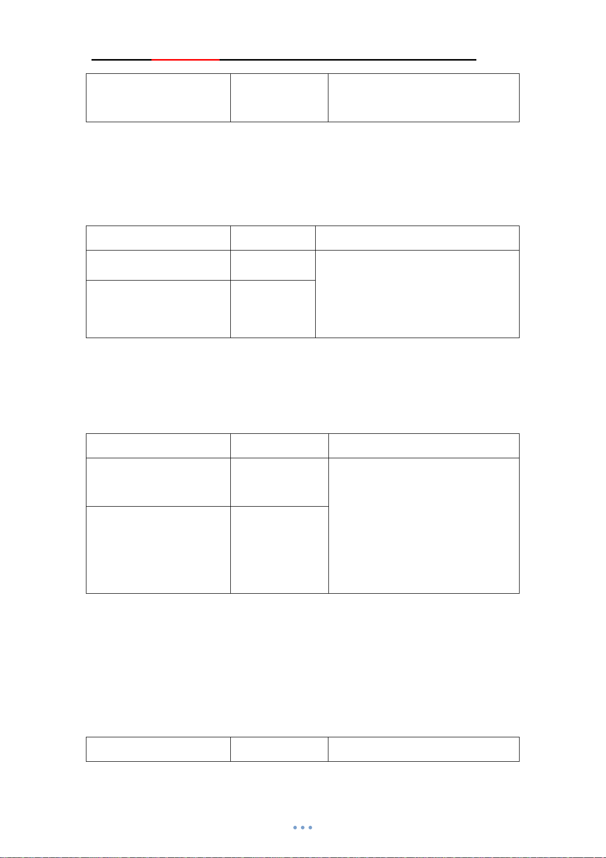
JDY-24M Super BLE Bluetooth Module
AT+SUBTYPE +SUBTYPE=<Para
Default:0
m>
Note: After the SUBTYPE is set to 1, the level of the remote device controlled by the INPUT key will change as
the level of its OUTPUT pin.
For example, INPUT1 controls the remote device INPUT1 level to high level, and its own INPUT1 pin will
also become high level.
42、Set/query - Learn switch enable
Instruction Response Parameter
AT+LEARN<Param> +OK Param:1 or 0
AT+LEARN +LEARN=<Para
m>
1:Button and output pin learn mode on
0:Button and output pin learn mode off
Default:0
Note: When LEARN is set to 1, it means the parameters of INPUT pin set by AT+KEYare completely invalid. The
parameters of key sending and receiving will be acquired by AT+LEAVAL or key learning.
For key learning configuration, please refer to the document Switch panel instructions. PDF.
43、Set/query - Learn parameter
Instruction Response Parameter
AT+LEAVAL
<P1>,<P2>,<P3>
AT+LEAVAL +LEAVAL=
+OK P1:OUTPUT pin number of current
device
P2:Code sender INPUT pin number
<P1>,<P2>,<P3>
P3:Code sender short address
(0001-FF00)
Default:0,0,0000
When LEARN mode is on, AT+LEAVALinstruction configures parameters.
Example 1: Remote 0008 device KEY1 simultaneously controls the current device's OUTPUT1 and OUTPUT2
levels
Current device sends instruction: AT+LEAVAL1,1,0008 send AT+LEAVAL2,1,154A
Example 2: Remote 0008 device KEY2 controls the current device's OUTPUT5 level
Current device sends instruction: AT+LEAVAL5,2,0008
44、Set/query - Turn on one key binding to connect the strongest signal slave
Instruction Response Parameter
Page 22

JDY-24M Super BLE Bluetooth Module
Param:00 or ff
AT+DEVCLSS<Param
>
+OK
F1:indicates that one key binding
function is turned on (In ROLE1mode,
support pressing PWRC pin to bind and
AT+DEVCLSS +DEVCLSS=<Para
m>
connect to the strongest signal slave
nearby)
Default:0
Example: In ROLE1 mode, press PWRC pin to automatically bind the strongest signal slave nearby and send
AT+DEVCLSSF1
45、Set/query - Key label address addition
Instruction Response Parameter
AT+KLABEL<Param1>,<Par
am2>,<Param3>
AT+KLABEL<Param1>+KLABEL=<Param1>
+OK Param1:label number(Value 0-9)
Param2:action IO number(Value 1-5)
Param3 : label MAC address ( 12
character string)
,<Param2>,<Param3>
Default:0,0,000000000000
In ROLE8 key label detection mode, add bracelet or label,
For example, the MAC address of the bracelet is 112233445566. When the bracelet is close to JDY-24M, let OUT2
act. The instructions are as follows.
AT+KLABEL1,2,112233445566
We add another key label. The MAC address of the key label is 888888999999. When the key label is close to
JDY-24M, make OUT5 act, the instruction is: AT+KLABEL2,5,888888999999
46、Set/query - Overtime action time of opening a key label
Instruction Response Parameter
AT+KLTIME<Param>,<Para
m>
AT+KLTIME<Param> +KLTIME=<Param>,<
+OK Param1:label number(Value 0-9)
Param2:overtime time(Value 0-9)
Param2 default:3
Param>
In ROLE8 key label detection mode, bracelet and key labels have been added,
Example: Set the overtime time of the bracelet to 9 seconds. (After the bracelet is close to JDY-24M, OUT2
always outputs high level. When the bracelet leave the JDY-24M range, OUT2 reverts to low level in 9 seconds. If
the bracelet enters the JDY-24M range again within the 9 seconds, OUT2 outputs high level again.)
Instruction: AT+KLTIME1,9
Page 23

JDY-24M Super BLE Bluetooth Module
47、Set/query - Sensitivity of opening a key label
Instruction Response Parameter
AT+KLRSSI<Param>,<Param
>
AT+KLRSSI<Param> +KLRSSI=<Param>,<
+OK Param1:label number(Value 0-9)
Param2:sensitivity(Value 00-99)
Param2 default:99
Param>
In ROLE8 key label detection mode, bracelet and key labels have been added,
Example: Set the receiving range of the bracelet to a relatively close distance. Only when the bracelet is in this
range can the OUT pin of JDY-24M act.
Instruction: AT+KLRSSI30
The above parameter setting is 30. Of course, the value of KLRSSI can be set anyone from 00 to 99. Users can set
it according to their own requirements.
Page 24

JDY-24M Super BLE Bluetooth Module
. APP terminal instruction
Ⅸ
UUID list
Service UUID: FFE0 (Service UUID)
Service UUID: FFE1 (Used for transparent transmission)
Service UUID: FFE2 (Used for transparent transmission)
Service UUID: FFE3 (MESH data receiving and sending, MESH instruction receiving
and sending, APP control IO, parameter configuration)
APP command instructions (Not mesh mode)
1)APP transparent transmission (Use characteristic UUID: FFE1)
0XFFE1 is APP transparent transmission characteristic UUID(Applied to IOS,Android
or Wechat applet communication)
2)APP sends data or instruction to MESH (Use characteristic FFE3)
Data format HEAD(2byte) + CMD(1byte) + MADDR(2byte) + data(1-16byte)
Example 1: APP broadcasts data to all devices:31323334353637383930
Instruction 1: F10100FFFF31323334353637383930
Example 2: APP sends 1122334455 data to 0008 device serial port
Instruction 2: F1010000081122334455
Example 3: APP sets OUT1 pin of all modules to high level
Instruction 3: F10110FFFFAAB1E70101
Example 4: APP sets OUT1 pin of 0008 module to low level
Instruction 4: F101100008AAB1E70100
Example 5: APP reads all OUT pin levels of 0008 module
Instruction 5: F101310008F0B100
Example 6: APP reads all INPUT pin levels of module 0008
Instruction 6: F101310008F1B101
Example 7: APP reads all INPUT pin levels of 0008 module
Instruction 7: F101310008F1B101
Note: The above are just some examples of APP sending data to MESH, including setting NETID, setting
MADDR, communicating with friend node, setting friend type, setting route or terminal node, etc.lease refer to
MESH user manual. PDF. The MESH communication format of APP is the same as that of AT instruction of
serial port, except the data head.
Page 25
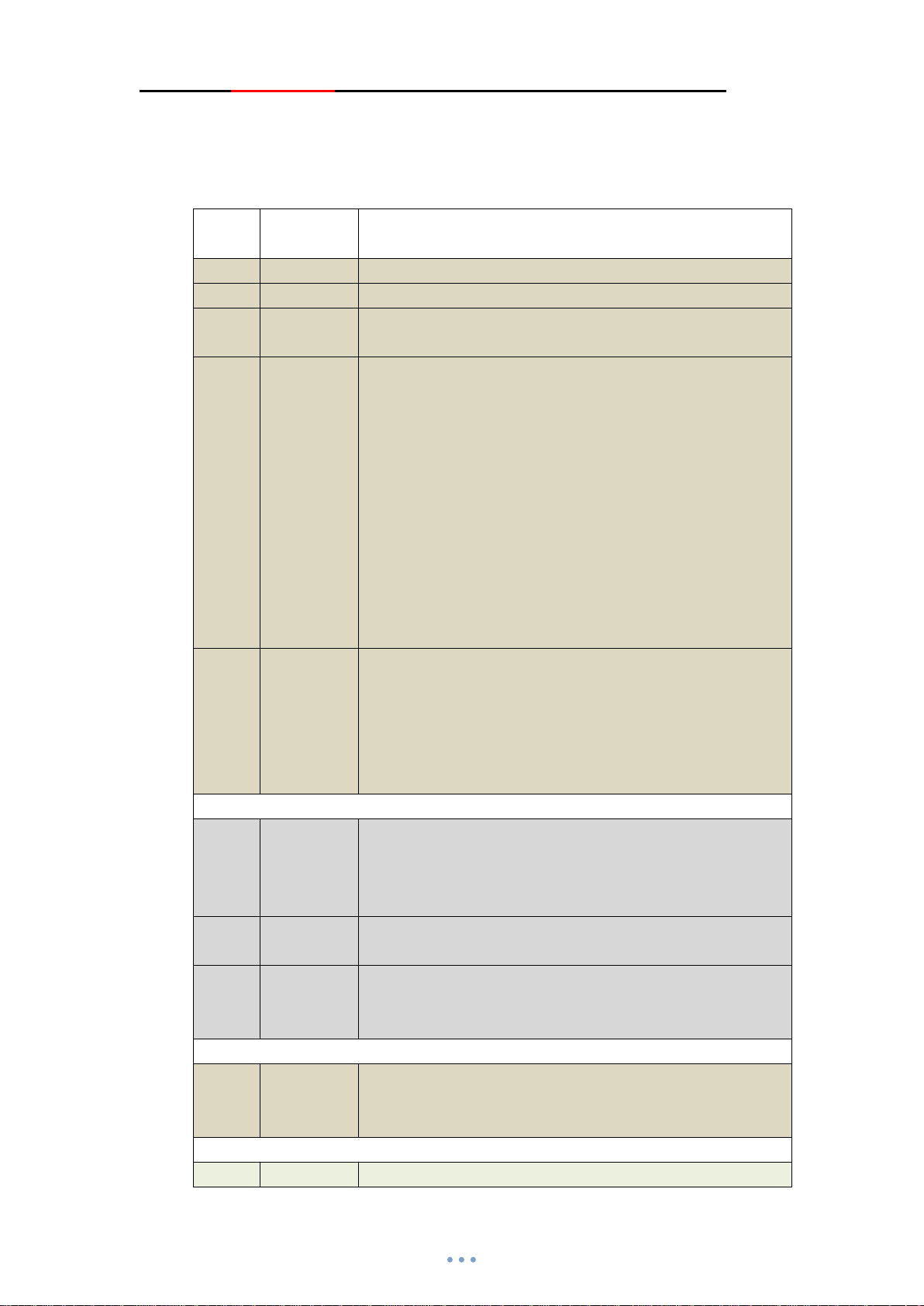
JDY-24M Super BLE Bluetooth Module
3)APP configures current device instruction table ( Use characteristic UUID :
0XFFE3)
This instruction is only used for the current APP connected device parameter
configuration.
Instru
ction
F202 NETID APP sets the network NETID, with the length of 2 bytes
F303 MADDR APP sets short address, MADDR length is 2 bytes
F404 MCLSS APP sets network type, MCLSS length is 1 byte, 0 represents
F505 ROLE APP sets the working mode, and the length of ROLE is 1 byte,
F606 x1x2x3x3x5 APP sets key parameters
Data Function description
router, 1 represents terminal device
0:Indicates slave transparent transmission
1:Indicates master transparent transmission
2:BLE broadcast probe mode
3:iBeacon mode
4:iBeacon probe mode
5:MESH network mode
6 : Multi-connected and multi machine mode ( Support
simultaneous connection transparent transmission of 4 masters)
7 : Multi-connected master slave mode ( Support master to
connect 4 slaves)
8:Key label detection mode
x1: Indicates key number, range (1 to 5)
x2x3:Indicates the target address of key, range (0000-ffff)
x4:Indicates the target output pin number, range (1 to 5)
x5:Indicates whether the target receive data and the serial port
output at the same time, range (0-1)
F707 SUBTYPE SUBTYPE=1 in MESH mode indicates that OUT and target are
synchronized
SUBTYPE=0 in MESH mode indicates that OUT and target are
not synchronized
F808 LEARN LEARN=1 in MESH mode indicates open learning function
0 indicates close learning function
x1 indicates the OUTPUT pin number of the current device
F909 x1x2x3x4
FA01 DEVCLSS DEVCLSS=F1 indicates open the function of one key bind and
x2 indicates code sender INPUT pin number
x3x4 indicates the short address of the code sender (0001-FF00)
connect to the strongest signal slave
DEVCLSS =0 indicates close
x1:
Label number(Value 0x00-0x09)
Page 26
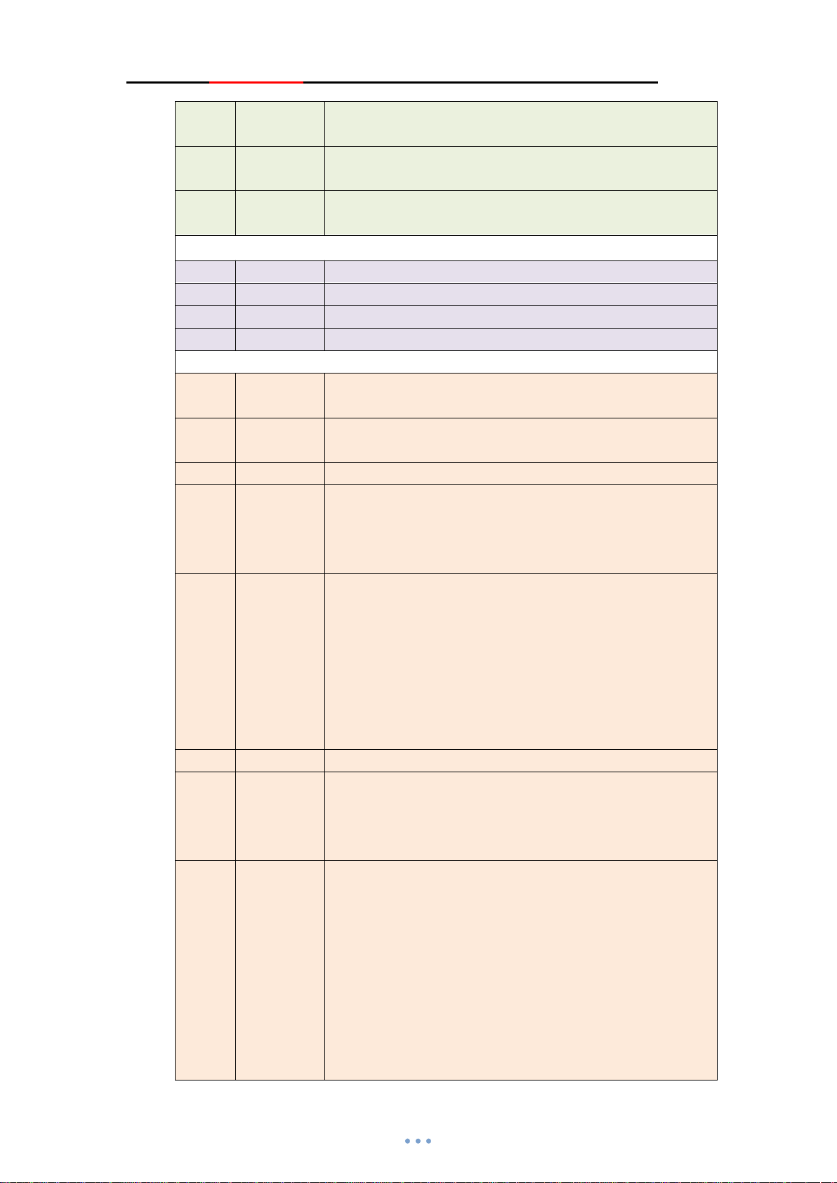
JDY-24M Super BLE Bluetooth Module
FA02 x1x2mac x2:Action IO number(Value 0x01-0x05)
Mac:Label MAC address(Value 0x000000000000-0xffffffffffff)
FA03 x1x2 x1:
FA04 x1x2 x1:
B101 UUID UUID of iBeacon, length 16 bytes
B202 MAJOR MAJOR of iBeacon, length 2 bytes
B303 MINOR MINOR of iBeacon, length 2 bytes
B404 SING Signal verification value of iBeacon at 1m, length 1byte
A1E1 F101 APP sends this instruction to restart the module, fixed
A2E2 NAME NAME is broadcast name, the maximum length of NAME is 18
A3E3 PIN PIN connection password, PIN length is 4 bytes
A4E4 TYPE TYPE matching method, length is 1byte
A5E5 BAUD BAUD is baud rate, length is 1byte
A6E6 01 APP disconnect instruction, fixed instruction(A6E601)
A7E7 STARTEN STARTEN Whether it is power on sleep, the length is 1 byte
A8E8 ADVIN ADVIN is broadcast interval, the length is 1 byte
Label number(Value 0x00-0x09)
x2:Overtime time
Label number(Value 0x00-0x09)
x2:
Sensitivity(Value 0x00-0x99)
instruction (A1E1F101)
bytes
0:No password for connection
1:Password connection and not binding
2:Password connection and binding
2:2400
3:4800
4:9600
5:19200
6:38400
7:57600
8:115200
1 : Power on wake-up, sleep can be controlled by sleep
instruction
0:Power on sleep, connect wake-up, disconnect sleep
1:100mS
2:200mS
3:300mS
4:500mS
5:700mS
6:100mS
7:1500mS
8:3000mS
9:60000mS
(Value 0x00-0x09)
Page 27

JDY-24M Super BLE Bluetooth Module
A9E9 POWER POWER is transmitting power, the length is 1 byte
0:-20db
1:0db
2:2db
3:3db
4:4db
AAEA DEFAULT Restore factory configuration
C101 NULL Read module software version number
C102 NULL Read broadcast name value, length (1 to 18) bytes
C103 NULL Read password value, length 4 bytes
C104 NULL Read password type value, length 1 byte
C105 NULL Read baud rate value, length 1 byte
C106 NULL Read power on sleep value, length 1 byte
C107 ADVSTAT
C108 NULL APP reads transmitting power
C109 NULL APP reads ROLE working mode
C201 NULL Read the UUID of iBeacon, length 16 bytes
C202 NULL Read the MAJOR of iBeacon, length 2 bytes
C203 NULL Read the MINOR of iBeacon, length 2 bytes
C204 NULL Read the SING of iBeacon, length 1 byte
C301 NULL Read MESH network NETID, length 2 bytes
C302 NULL Read MESH network MADDR, length 2 bytes
C303 NULL Read MESH network type MCLSS, length 1 byte
C304 NULL APP reads key 1 parameter
C305 NULL APP reads key 2 parameter
C306 NULL APP reads key 3 parameter
C307 NULL APP reads key 4 parameter
C308 NULL APP reads key 5 parameter
C309 NULL Read SUBTYPE parameter
C30A NULL Read LEARN parameter
C30B NULL Read learner OUTPUT1 LEARN parameter
C30C NULL Read learner OUTPUT2 LEARN parameter
C30D NULL Read learner OUTPUT3 LEARN parameter
C30E NULL Read learner OUTPUT4 LEARN parameter
C30F NULL Read learner OUTPUT5 LEARN parameter
C310 NULL Read DEVCLSS parameter
C311 x1 Read KLABEL parameter
Page 28
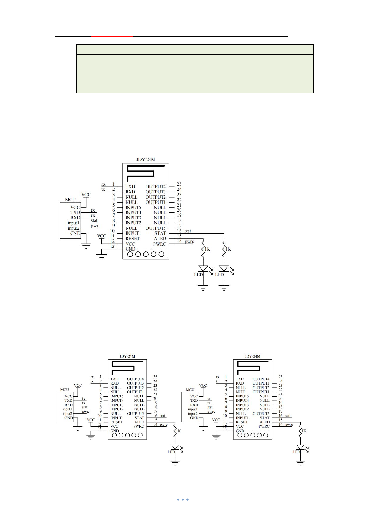
JDY-24M Super BLE Bluetooth Module
x1:Label number(Value 0x00-0x09)
C312 x1 Read KLTIME parameter
x1:
Label number(Value 0x00-0x09)
C313 x1 Read KLRSSI parameter
x1:
Label number(Value 0x00-0x09)
Ⅹ. Wiring diagram of JDY-24M module application
10.1 Wiring diagram of data transparent transmission between JDY-24M and mobile phone
(IOS, Android) APP and applet
Note: Only 4 wires (VCC, GND, RXD, TXD) need to be connected for general transparent
transmission. MCU can judge the working state (connection, disconnection) of Bluetooth through
serial port state. If Bluetooth output status (connection, disconnection) is not required, it can be
determined by Bluetooth status pin or by pulling down PWRC pin (send AT+STAT).
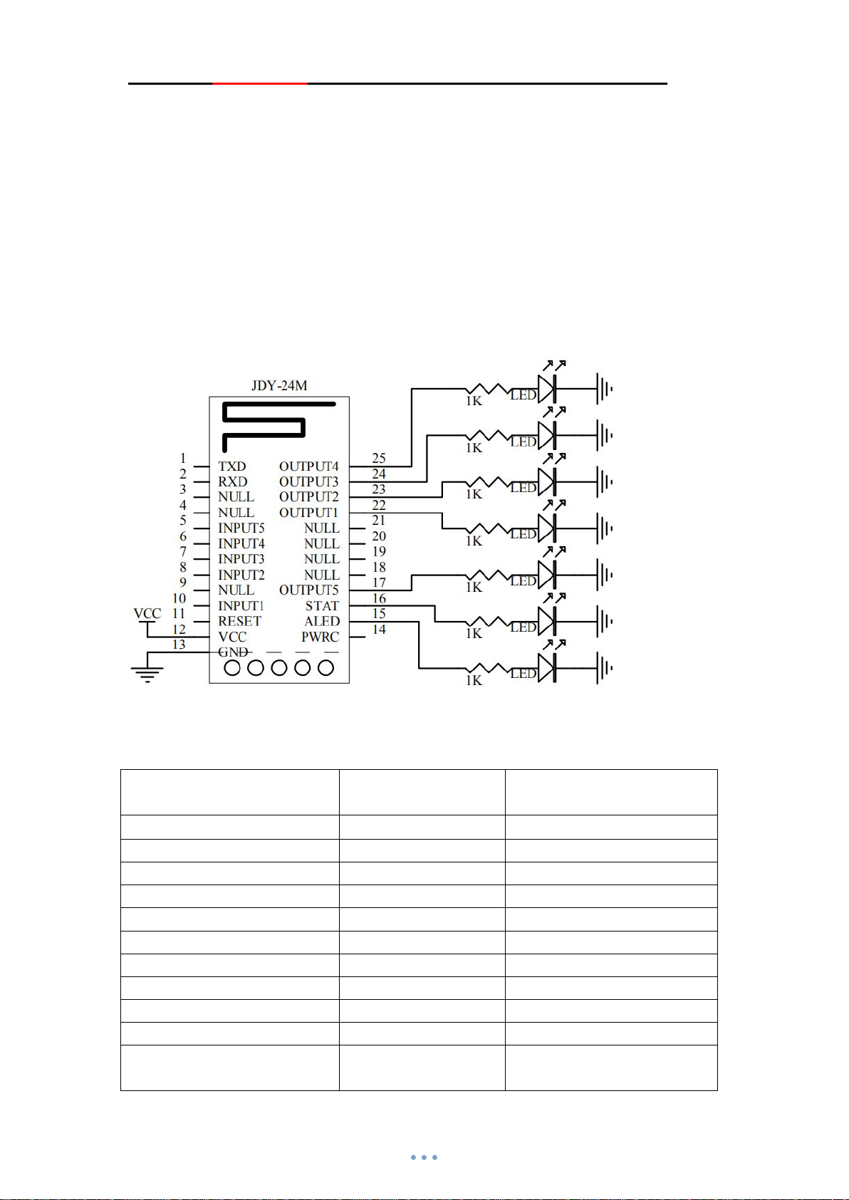
10.2 JDY-24M non MESH master-slave transparent transmission wiring diagram
Page 29
JDY-24M Super BLE Bluetooth Module
The master-slave communication speed rate supports continuous data transmission at all baud
rates (under 115200 baud rate, the data can be transmitted without delay and can be continuously
transmitted and received)
Master instruction: AT+ROLE1
AT+RESET
Search slave instruction: AT+INQ
After the slave is searched, use AT+CONA to connect the MAC address of the
searched slave.
10.3 Wiring diagram of output pin level of APP control module in JDY-24M non network
mode
In the AT+ROLE0, AT+ROLE3, AT+ROLE6, AT+ROLE7 modes, it support APP to directly
control OUTPUT pin level
APP selects the FFE2 characteristic and sends instructions as follows
Function APP instruction
(Characteristic FFE2)
Control OUTPUT1 pin high level E7F101
Control OUTPUT1 pin low level E7F100
Control OUTPUT2 pin high level E7F201
Control OUTPUT2 pin low level E7F200
Control OUTPUT3 pin high level E7F301
Control OUTPUT3 pin low level E7F300
Control OUTPUT4 pin high level E7F401
Control OUTPUT4 pin low level E7F400
Control OUTPUT5 pin high level E7F501
Control OUTPUT5 pin low level E7F500
APP reads 5 output pin level E7FAFF Return E7FAFF0000000000
5 colors mean 5 output IO levels
Description
Page 30
JDY-24M Super BLE Bluetooth Module
In the non network module, APP can not only directly control the OUTPUT pin level, but also
support transparent transmission.
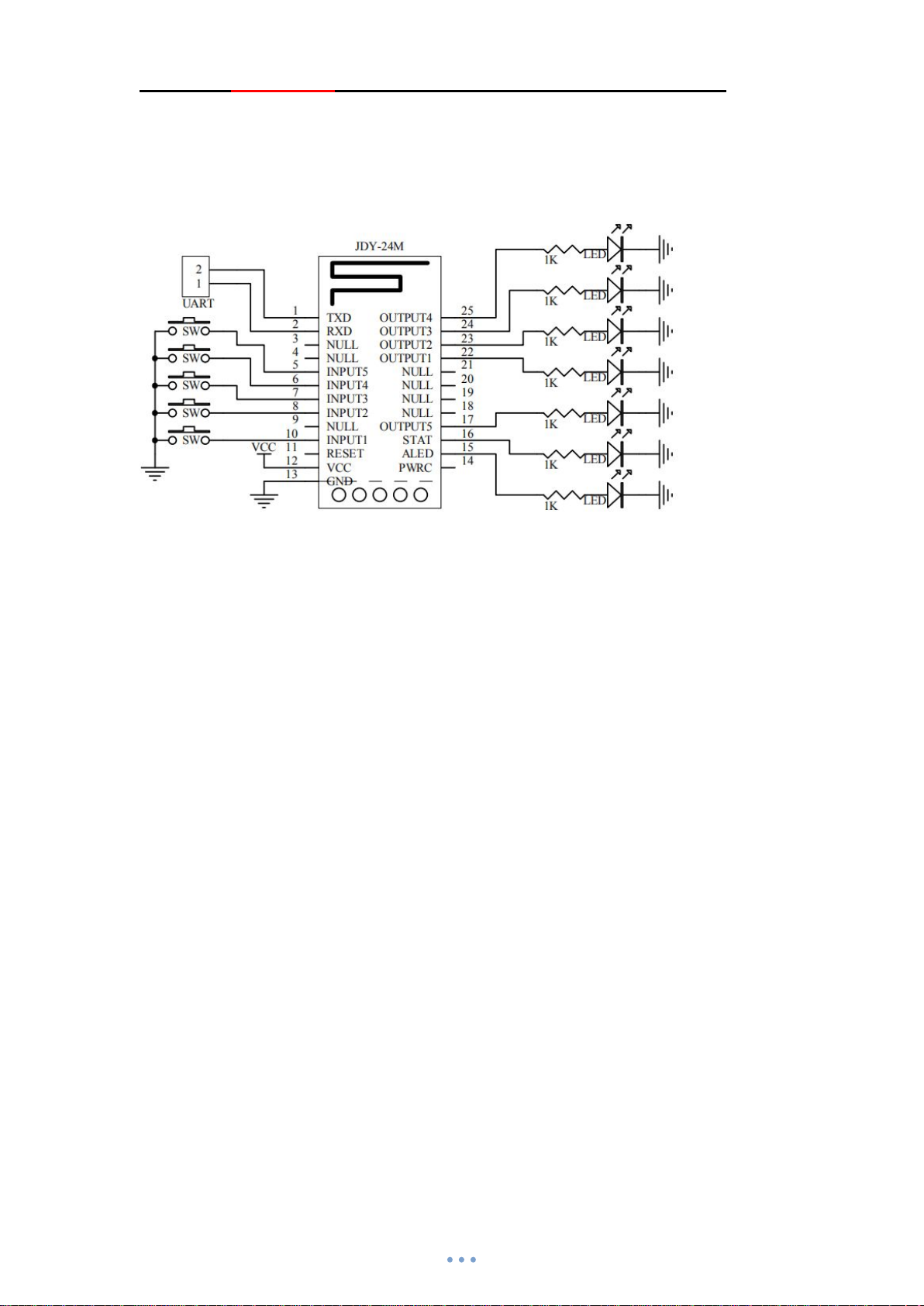
10.4 JDY-24M network IO control wiring diagram
This circuit is mainly used for routing nodes. The key supports to control the IO or serial port
output key information of all nodes (routing, terminal) in the network.
Network IO control instructions are as follows:
AT+ROLE5
AT+RESET
After configuration, IO control can be carried out. By default, the short address of INPUT1 to
INPUT5 is FFFF. Press the INPUT pin SW key by default to output IO to control the
corresponding OUTPUT of all devices in the network. If you do not need to control the OUTPUT
pin of all devices, you can configure it with the following instructions.
Example 1: The INPUT5 key with the local machine address of 0005 needs to control the
OUTPUT5 pin level of 0008 device
0005 local machine instruction as follows:AT+KEY5,0008,5,0
Example 2: The INPUT1 key with the local machine address of 0005 needs to control the
OUTPUT3 pin level of 0008 device
0005 local machine instruction as follows:AT+KEY1,0008,3,0
Note that this mode is non learning mode key switch and output IO control. AT+LEARN0 and
AT+SUBTYPE0 are both set to 0, and the module factory default is 0.
Page 31
JDY-24M Super BLE Bluetooth Module
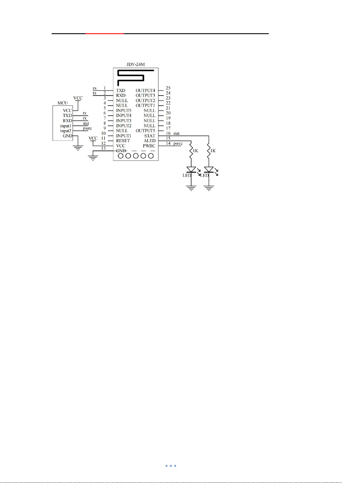
10.5 Serial port communication wiring diagram between MCU and MCU in JDY-24M
network
In this wiring, the user MCU can realize wireless serial port communication between multiple
MCU, and can also control the output IO level of all nodes, and read the input IO level status
(input1 to input5).
Example 1: Serial port of local 0005 device sends 112233445566 hex data to the serial port of
target 0008 device
Instruction: 41 54 2b 4d 45 53 48 00 00 08 31 32 33 0d 0a
Example 2: Serial port of local 0005 device serial port sends 112233445566 hex data to all device
serial ports in the network
Instruction: 41 54 2b 4d 45 53 48 00 ff ff 31 32 33 0d 0a
Example 3: Serial port of local 0005 device reads 5 OUTPUT pin levels of target 0008 device
Instruction: 41 54 2b 4d 45 53 48 31 00 08 f0 b1 00 0d 0a
Return: F0 00 07 00 08 00 00 00 00 00
Example 4: Serial port of local 0005 device reads 5 INPUT pin levels of target 0008 device
Instruction: 41 54 2b 4d 45 53 48 00 00 08 f1 b1 01 0d 0a
Return: F0 01 07 00 08 01 01 01 01 01
Example 5: Serial port of local 0005 device controls the OUTPUT1 pin of the target 0008 device
as high level
Instruction: 41 54 2b 4d 45 53 48 10 00 08 aa b1 e7 01 01 0d 0a
Example 6: Serial port of local 0005 device controls the OUTPUT pin of the target 0008 device as
high level
Instruction: 41 54 2b 4d 45 53 48 10 00 08 ab b1 e7 ff 1f 0d 0a
Page 32
JDY-24M Super BLE Bluetooth Module
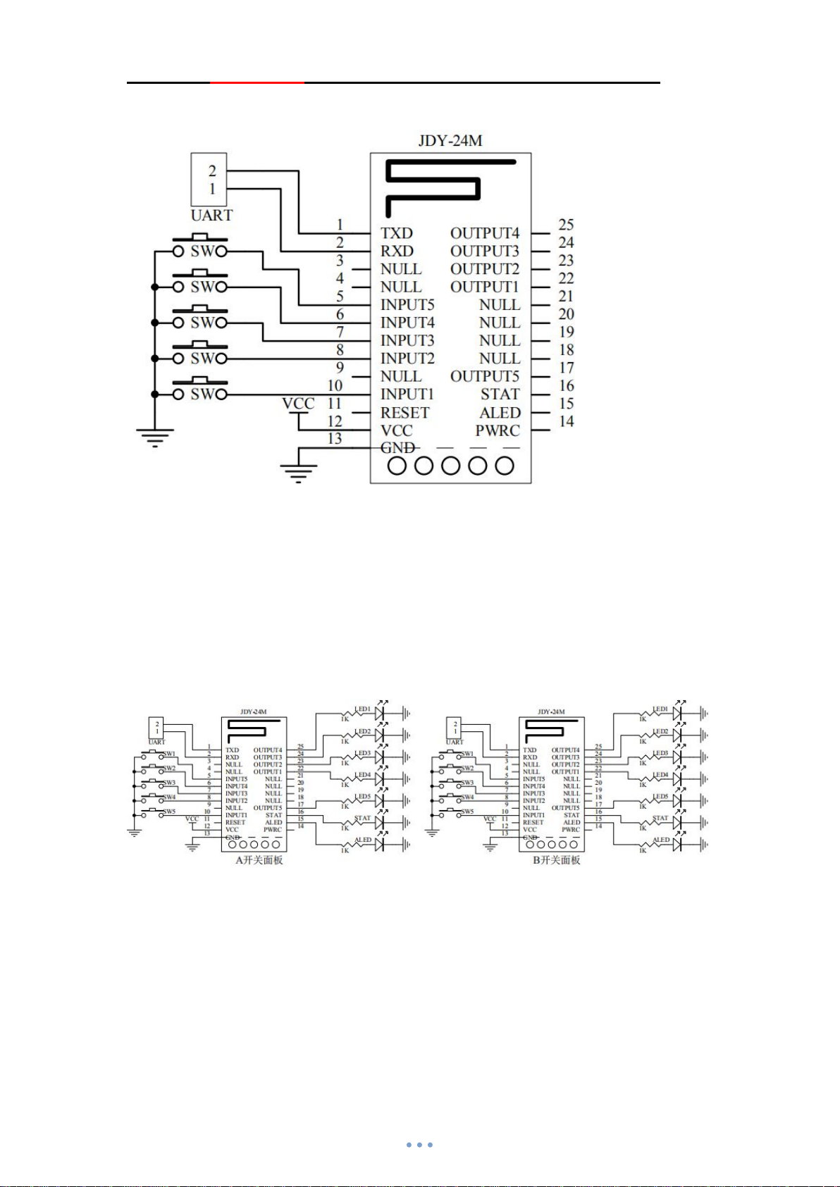
10.6 JDY-24M network remote control node wiring diagram
This node is generally used for panel switch and remote controller. The terminal node is generally
powered on sleep. Press the key to send data, and release the key to continue deep sleep
immediately.
Configure remote control node instruction
1.Configure to MESH mode:AT+ROLE5
2.Configured as a low-power consumption node: AT+MCLSS1
3.Restart to take effect:AT+RESET
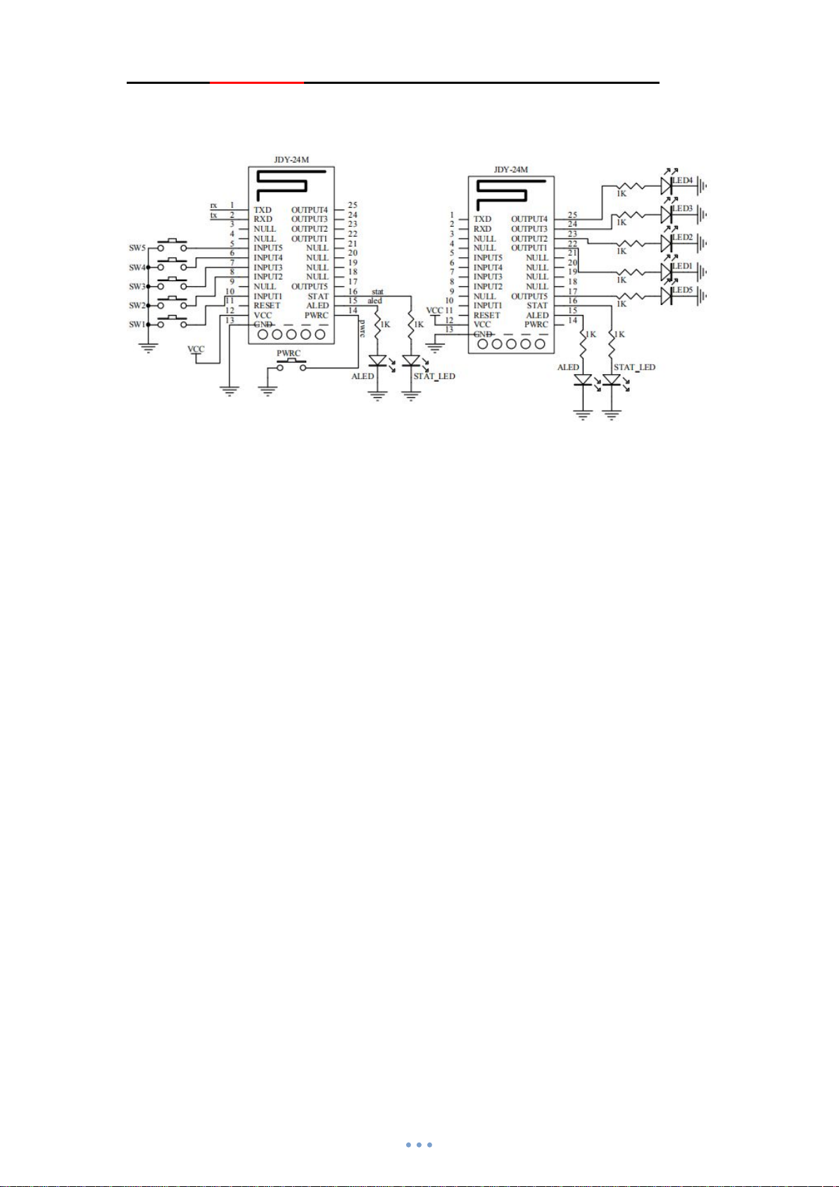
10.7 Application wiring diagram of network switch panel
Before the installation of the switch panel, it is necessary to configure the module network, and
open the parameters such as AT+SUBTYPE1 and AT+LEARN1 to factory setting, and learn
during installation. The above circuit diagram is the application circuit diagram of the switch
panel. The above two devices support hundreds or thousands of circuit devices in the practical
application.
Example: We control the level of LED2 and LED5 of B switch panel by SW1 of A switch panel.
At this time, LED2 and LED5 of B switch panel need to learn the key of SW1.
Step 1: Make A switch panel enter the code sender mode, click the PWRC pin on A switch panel,
and the LED light on a switch panel flashes slowly, indicating that the code sender mode has
Page 33

JDY-24M Super BLE Bluetooth Module
entered.
Step 2: Make B switch panel enter the learner mode, double-click the PWRC pin of the B switch
panel, the ALED of the B switch panel is off, and the STAT pin flashes slowly, indicating that the
learner mode has been entered. First, learn LED2 (press SW2 of B switch panel), at this time,
LED2 light flashes (once a second), then press SW1 of A switch panel code sender, LED2 of B
switch panel learns the value sent by SW1 of A switch panel, and LED2 of B switch panel will be
on, which indicates that LED2 has learned successfully. Second, press SW5 of B switch panel, at
this time, LED5 of B switch panel flashes, which indicates that LED5 learning begins. Then press
SW1 of switch panel A, LED5 of switch panel will be on, which indicates that learning has been
successful.
Step 3: A switch panel quit code sender mode, click PWRC pin, and LED of ALED pin flashes
(once in 1 second), indicating that the code sender mode has quit and normal working mode has
been entered.
Step 4: B switch panel quit learner mode, double-click PWRC pin, and LED of ALED pin flashes
(once in 1 second), indicating that the learner mode has quit and normal working mode has been
entered.
Step 5: At this time, SW1 of A switch panel can control the level of LED2 and LED5 of B switch
panel.
Clear learning code, press PWRC pin for more than 6 seconds, and all learning codes will be
cleared automatically.
The above is the configuration of the switch panel by learning mode. If using APP or serial port to
configure, it will be very simple to use.
If the user configures the above functions through the serial port, only several instructions are
needed.
A switch panel address is 0008, B switch panel address is 0009
1、AT+LEARN1
2、AT+SUBTYPE1
3、AT+LEAVAL2,1,0008
4、AT+LEAVAL5,1,0008
Page 34
JDY-24M Super BLE Bluetooth Module
10.8 Application wiring diagram of one key binding and connect to the strongest signal slave
nearby
Bluetooth remote control transmitter Bluetooth remote control receiver
Bluetooth remote control application instruction mode 1 (LED light level flip)
Bluetooth transmitter configuration instruction Bluetooth receiver configuration instruction
AT+ROLE1 AT+ROLE0
AT+DEVCLSSF1 AT+RESET
AT+RESET
After the configuration of instructions through the above transmitter and receiver, the
transmitter presses the SW5 button briefly, and the transmitter automatically searches for and
bind the strongest signal receiver nearby.After the automatic connection, the LED of STAT pin is
on, indicating that the binding is successful. After the binding is successful, the transmitter presses
the SW1, SW2, SW3, SW4, PWRC pins briefly to control the receiver of LED1, LED2, LED3,
LED4, LED5. The control mode is level flip mode.
Bluetooth remote control application instruction mode 2 (pulse level)
Bluetooth transmitter configuration instruction Bluetooth receiver configuration instruction
AT+ROLE1 AT+ROLE0
AT+DEVCLSSF2 AT+RESET
AT+RESET
After the configuration of instructions through the above transmitter and receiver, the
transmitter presses the SW5 button briefly, and the transmitter automatically searches for and
bind the strongest signal receiver nearby.After the automatic connection, the LED of STAT pin is
on, indicating that the binding is successful. After the binding is successful, the transmitter presses
the SW1, SW2, SW3, SW4, PWRC pins briefly to control the receiver of LED1, LED2, LED3,
LED4, LED5. The control mode is pulse level.
In the mode of AT+DEVCLSSF1 or AT+DEVCLSSF2, the transmitter supports long press of
SW5 button for 6 seconds to enter into deep sleep. After sleep, the current will be several uA, and
after sleep, it can be waken up by short press of PWRC pin.
Page 35
JDY-24M Super BLE Bluetooth Module
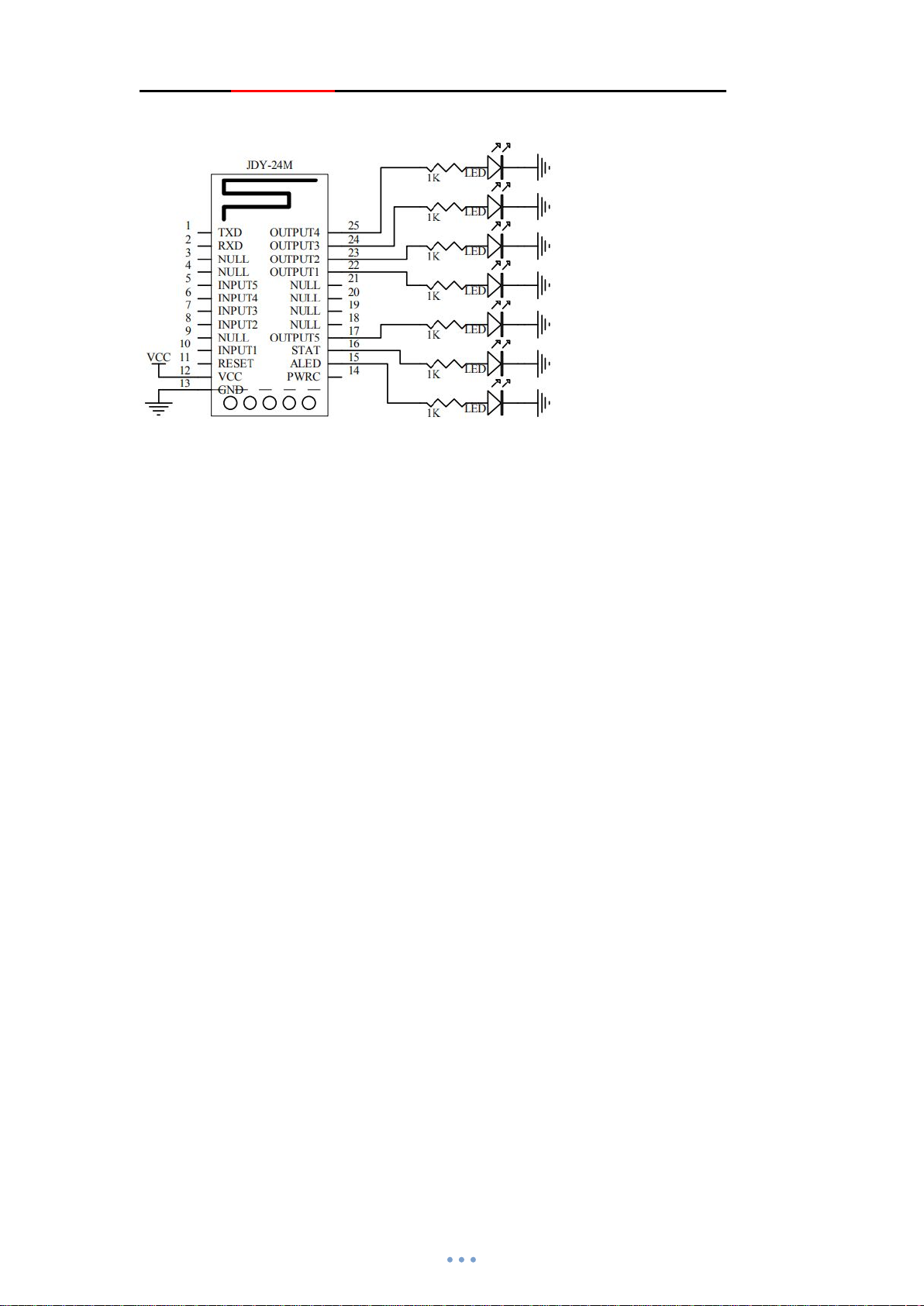
10.9 Key label detection application wiring diagram
Key label detection is generally used in gate switch, check in, anti-loss and other fields.
When JDY-24M detects the key label or bracelet approaching, OUT outputs pin action.
Example: the MAC of the bracelet is 112233445566. When the bracelet is close, the OUT2 pin
action instruction is as follows.
AT+ROLE8
AT+KLABEL1,2,112233445566
AT+RESET
JDY-24M supports binding 10 labels and 5 action OUT pins. The received label address will
be output from the serial port. If you need to expand the number of labels, you can set the
label address to the same, so that JDY-24M will have no upper limit on the number of labels,
and users can also get the label address through MCU added by the serial port and to
process MCU.
 Loading...