

Page 1
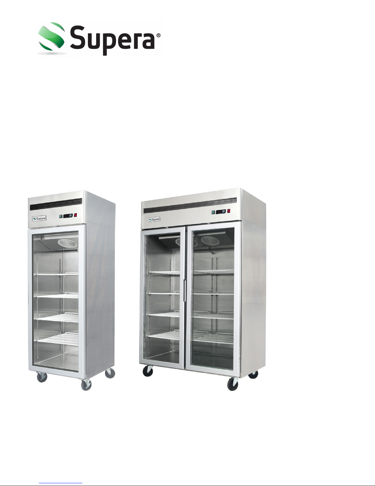
Instruction Manual
Glass Door Reach-Ins
Models:
GF1R-1
GF2R-1
G1R-1
G2R-1
SUPERA Customer Care Toll-Free Service Line:
information, please visit our website at
1-866-953-3288
For additional product and warranty
www.SuperaCo.com
Page 2

Contents
1. Preface ....................................................................................................................................... 3
2. Use of the Equipment ................................................................................................................ 3
3. Technical Features ..................................................................................................................... 4
4. Operation ................................................................................................................................... 4
5. Control Unit ................................................................................................................................ 4
6. Handling ..................................................................................................................................... 5
7. Installation Procedure ................................................................................................................ 5
8. Connecting to the Main Power Supply ...................................................................................... 5
9. Maintenance Instructions .......................................................................................................... 6
10. Troubleshooting ....................................................................................................................... 7
11. Technical service ...................................................................................................................... 7
12. Configuration Sketch Map ....................................................................................................... 7
Operating Instructions .................................................................................................................... 8
Technical Parameters .................................................................................................................... 11
Offical Approval and Rules ............................................................................................................ 12
©Supera
V.1.0 | October 2014
2
Page 3

1. Preface
This Instruction manual provides all the necessary information regarding:
• Use of the refrigerator
• Technical specifications
• Installation and handling
• Operator procedures and instructions maintenance operation
The manual is to be considered an integral part of the refrigerator and should be stored in a
safe place for further consult to permit a good working life of the refrigerator.
ATTENTION
The manufacturer cannot be held liable in the following cases:
• Improper installation (not in accordance with the guidelines indicated in this manual)
• Misuse of the refrigerator
• Power supply defects
• Improper or inadequate maintenance
• Unauthorized modification or tampering
• Use of non-original spare parts
• Partial or total failure to comply with the instructions
All electrical equipment can be hazardous to health. Current standards and legal requirements
must be complied with during the installation and use of any equipment.
2. Use of the Equipment
The refrigerators are for preserving fresh perishable foods, with a built-in refrigerated unit.
The operating temperature for refrigeration is:
• between +2°C and +10°C at room temperature of +32°C an 60%RD.
The operating temperature for frozen food maintenance is:
• between -6°C and -18°C at room temperature of +32°C an 60% RD.
©Supera
V.1.0 | October 2014
3
Page 4

3. Technical Features
The refrigerator is a ventilated system, the evaporator is in a separate insulated box on the top.
All the materials used in the manufacturing of this unit are guaranteed to be suitable for use
with perishable foods. The gases used in the refrigerators are R-134a; in the refrigerator for
frozen food maintenance is R-404a.
The refrigerating circuit is in compliance with the current normative.
4. Operation
The gas in the refrigerating circuit is first compressed, liquefied and then evaporated in the
ventilated evaporator, situated on the top of the container.
This cycle involves the absorption of heat from the air in the refrigerator compartment and is
then cooled. The heat produced is then dissipated to the outside environment by a condenser
unit located on the top of the refrigerator.
5. Control Unit
The refrigerator responds to commands from a "digital control unit" and a "main switch pilot
light" in the top panel of the refrigerator.
The "main switch pilot light" is for turning on the power supply.
The red pilot light comes on to indicate that the unit is connected to the main electricity and to
start work.
The red pilot light comes off to indicate that the unit is disconnected and doesn't work. The
"digital control unit" is for the regulation of all parameters to provide the correct working of the
refrigerator. Please consult all parameters in the attachment manual of the "digital control
unit".
This manual is part of the instruction manual and is very important in case of service.
Applied refrigerant belongs to non-flammable refrigerant.
©Supera
V.1.0 | October 2014
4
Page 5

6. Handli
The refrigerator will arrive in PET film and packed in cardboard box on a
wood pallet.
The refrigerator must be transported and handled with care to avoid
posing a hazard to persons or property.
Never place a refrigerator with an in-built refrigerated unit on its side or turn it upside down.
This may damage or impair operation of the refrigerated unit. We cannot be held liable for any
damage or defects arising directly or indirectly from improper handling of the equipment or
non-compliance with the safeguards illustrated above.
ng
7. Installation Procedure
Install the unit in the best ventilated part of the room. Don't install the refrigerator near a
direct heat source.
• Remove the straps securing the cardboard packing Remove the cardboard covering.
• Remove the PET protection film.
• Clean the refrigerator with mild detergent and then dry it with a soft cloth.
8. Connecting to the Main Power Supply
This operation must be carried out by qualified professionals.
The refrigerators are supplied complete with a power supply
cable for the connection to the main power supply. A
thermomagnetic circuit breaker (not supplied) must be
installed between the main power point and the power supply
cable of the refrigerator.
Before proceeding make sure that:
©Supera
V.1.0 | October 2014
5
Page 6

The main voltage corresponds to the voltage on the refrigerator 220V/50Hz/1 Ph;
To ensure proper operation it is essential for the power supply voltage to come within a range
of +/- 6% of the unit's rated voltage. The electric system to which the refrigerator is sized to
cater for the rated electric output of the buffet unit being installed. The electronic system to
which the refrigerator is connected is made in compliance with current standard requirements.
The electric connections and the installation of the thermomagnetic circuit breaker have been
done by qualified person.
Connecting steps:
• Install a thermomagnetic circuit breaker suited to the rated output of the unit being
installed
• Connect the refrigerator unit to the thermomagnetic circuit breaker outlet
• Check that the refrigerator is in order as demonstrated by the pilot light incorporated in
the main switch coming on
9. Maintenance Instructions
The smooth operation and life of the equipment are mainly determined by correct and regular
maintenance.
Cleaning:
Regular cleaning of the refrigerator unit is strongly recommended each month. Please follow
the instructions below.
• Disconnect the refrigerator power supply cable from the main
prior to carrying out any type of cleaning operation.
• Cleaning the refrigerator surface: Clean the refrigerator with
mild detergent and then dry it with a soft cloth. Do not use
abrasive detergents!
• Cleaning the inside of the refrigerator: Clean the inside area
each month with a food safe detergent
• Cleaning the condenser: For an efficient operation of the
refrigerator it is advisable to clean the condenser regularly
approximately every 4 months with a dry brush or vacuum cleaner.
©Supera
V.1.0 | October 2014
6
Page 7

10. Troubleshooting
Refrigerator stops working (light off):
• Power supply failure
Remedies:
• Check that the plug is inserted properly in the socket
• Check that the switch on/off
• Check that the mains voltage powers the plug
Refrigerator temperature go up:
• Unit to near to a heat source Condenser dirty or close
Remedies:
• Move the counter or the heat source further away
• Clean the condenser
When replacing the lamp: Please turn off the power, remove the screw off the lampshade with
a screwdriver and replace the broken bulb with a new one which applies the same electrical
parameter.
11. Technical service
For technical service please contact the dealers technical department. Please provide the serial
number on the unit and the date of purchase.
12. Configuration Sketch Map
©Supera V.1.0 | October 2014
7
Page 8

T Series Reach-Ins
Operating Instructions
1. New upright air-cooling refrigerator should
be opened and ventilated it before it is in
use. After that, users should use warm water
to clean the inside.
2. After connecting the power supply, press the
"POWER" switch on the controller keyboard
(Green Indicator Light ON), the fridge will begin to work. The microcomputer controller,
installed in the controller keyboard, will automatically adjust the temperature ranges.
This intelligent digital controller works as: if the temperature increases and reaches set
point plus differential the compressor is started and then turned off when the
temperature reaches the set point value again.
3. Microcomputer Controller Operation
Instruction:
4. Microcomputer panel sketch map, meanings
of running indicator light and LED showing.
©Supera V.1.0 | October 2014
8
Page 9

5. To display target set point, in programming mode it selects a parameter or
confirm an operation.
To start a manual defrost.
In programming mode it browse
the parameter codes of increased the
displayed value.
In programming mode it browses
the parameter codes or decreases the
displayed value.
To lock or unlock the keyboard.
To enter in program mode.
To return to room temperature
display.
6. How to set the point:
• Push and immediately release the SET key, the set point will be showed;
• Push and immediately release the SET key or wait about 5 seconds to return to
normal visualization.
7. How to change the setpoint :
• Push the SET key for more than 2 seconds to change the Set point value; The value
of the set point will be displayed and the "°C" or "°F" LED starts blinking;
• To change the Set value push the or arrows.
• To memorize the new set point value push the SET key again or wait 10 second
8. How to start a manual defrost:
• Push the DEF key for more than 2 seconds and a manual defrost will start.
9. How to change a parameter value:
• To change the parameter's value operate as follows:
• Enter the Programming mode by pressing the keys for 3s
(“° C" or "°F" LED starts blinking).
• Select the required parameter
• Press the "SET" key to display its value
• Use or to change its value
• Press "SET" to store the new value and move to the following parameter
• To exit: Press or wait 15 seconds without pressing a key
©Supera
V.1.0 | October 2014
9
Page 10

NOTE: The set value is stored even when the procedure is exited by waiting for the time-out to
expire.
10. To lock the keyboard:
• Keep the keys pressed for more than 3 seconds
• The "OF" message will be displayed and the keyboard will be locked. If a key is pressed
more than 3 seconds the "OF" message will be displayed.
11. To unlock the keyboard .
• Keep pressed together for more than 3s
• The + A keys till the "on" message will be displayed .
12. Alarm Signaling
O
Our prod
ucts have been modified precisely before leaving the factory, so
to avoid damaging the compressor unit or other malfunctions, users
should not modify the microcomputer parameters privately.
©Supera
V.1.0 | October 2014
10
Page 11

Technical Parameters
Supera Glass Door Reach-Ins
V.1.0 | October 2014©Supera
11
Page 12

Offical Approval and Rules
A product with the SUPERA name incorporates the best in durability and low maintenance. We recognize,
however, that replacement parts and occasional professional service may be necessary to extend the life of
this unit. When service is needed, contact a SUPERA Authorized Service Agency, or your dealer. To avoid
confusion, always refer to the model number, serial number, and type of unit.
Supera Customer Care Toll-Free Service Line:
For additional product and warranty information, please visit our website at:
1-866-953-3288
www.SuperaCo.com
V.1.0 | October 2014©Supera
12
 Loading...