

䢇 This product is not a safety sensor. Its use is not
intended or designed to protect life and prevent body
injury or property damage from dangerous parts of
machinery. It is a normal pressure detection sensor.
䢇 In case this sensor is used within Japan, SI unit most
be used since use of pressure units in Japan is
restricted to SI units.
Gauge pressure
0 to
ⳮ101.3kPa 0 to 100.0kPa 0 to 1.000MPa
5.1 to
ⳮ101.3kPa ⳮ5.0 to 100.0kPa ⳮ0.050 to 1.000MPa
490kPa 1.47MPa
Non-corrosive gas
kgf/cm
2
, bar, psi, mmHg, inHg kgf/cm2, bar, psi
12 to 24V DC % Ripple P-P 10% or less
50mA or less
<Asian, North American (Standard NPN output • Flat • IP67 types)>
NPN open-collector transistor
• Maximum sink current: 100mA
•
Applied voltage: 30V DC or less (between comparative output and 0V)
• Residual voltage: 1V or less (at 100mA sink current)
0.4V or less (at 16mA sink current)
Equipped with 4 types of modes: hysteresis mode, window comparator mode, dual output mode, automatic sensitivity
setting mode (selectable by key operation)
1 digit (However, variable in hysteresis mode and 2 digits when using psi unit)
Within
Ⳳ0.2% F.S.Ⳳ1 digit
2.5ms or less
Incorporated
Output voltage: 1 to 5V (over rated pressure range)
Zero-point: within 1VⳲ5% F.S.
Span: within 4V
Ⳳ5% F.S.
Linearity: within
Ⳳ1% F.S.
Output impedance: 1kΩ approx.
3
1
/2 digit red LED display (Sampling rate: 4 times/sec. approx.)
5.1 to
ⳮ101.3kPa ⳮ5.0 to 100.0kPa ⳮ0.050 to 1.000MPa
LED bar display in steps of 10% F.S. approx.
Orange LED (lights up when Comparative Output 1 is ON)
Green LED (lights up when Comparative Output 2 is ON)
Standard • Flat • Light weight types: IP40 (IEC), IP67 type: IP67 (IEC)
ⳮ10 toⳭ50⬚C (No dew condensation or icing allowed), Storage: ⳮ10 toⳭ60⬚C
35 to 85% RH, Storage: 35 to 85% RH
Over ambient temperature range
ⳮ10 toⳭ50⬚C: withinⳲ1% F.S. of detected pressure at 20⬚C
Standard • Flat • IP67 types: Rc (PT)
1
/8 female thread, Light weight type: M5 female thread
Standard type: NPTF
1
/8 female thread, Flat • IP67 types: NPT
1
1
/8 female thread
Flat • IP67 types: G (PF)
1
/8 female thread
Front case: ABS, Rear case: PPS (glass fiber reinforced), Display surface: Acrylic
Pressure port attachment: Die-cast zinc alloy [Light weight type: POM (glass fiber reinforced), pressure port is brass (nickel plated)]
Front cover (IP67 type only): Polycarbonate
0.15mm
2
5-core oil resistant cabtyre cable, 2m long (IP67 type: 5m long)
Extension up to total 100m is possible with 0.3mm
2
, or more, cable.
Standard type: 95g approx., Flat type: 120g approx., IP67 type: 370g approx., Light weight type: 70g approx.
Hexagon-socket-head plug for pressure port: 1 No. (Standard type only), Pressure unit label: 1 No.
5
1
Pressure
Output voltage (V)
High pressure
(Positive pressure type)
High vacuum
(Vacuum pressure type)
INSTRUCTION MANUAL
LED Display • Digital Pressure Sensor
DP2 Series
For use outside Japan
Thank you very much for using SUNX sensors. Please read
this Instruction Manual carefully and thoroughly for the
correct and optimum use of this sensor. Kindly keep this
manual in a convenient place for quick reference.
1
SPECIFICATIONS
Type of pressure
Rated pressure range
Set pressure range
Pressure withstandability
Applicable fluid
Selectable units
Supply voltage
Current consumption
Comparative outputs
Comparative Output 1
Comparative Output 2
Output modes
Hysteresis
Repeatability
Response time
Short-circuit protection
Analog voltage output
Display
Displayable pressure range
Analog bar display
Comparative Output 1
Comparative Output 2
Protection
Ambient temperature
Ambient humidity
Temperature characteristics
Asian
North American
European
Material
Cable
Cable extension
Weight
Accessories
Operation
indicators
Pressure
port
<North American (Standard PNP output type), European>
PNP open-collector transistor
• Maximum source current: 100mA
•
Applied voltage: 30V DC or less (between comparative output and ⳭV)
• Residual voltage: 2V or less (at 100mA source current)
Ⳮ10
ⳮ15
Type
Asian
North American (Note)
European
Vacuum pressure Positive pressure
ⳮ101kPa type 100kPa type 1MPa type
Standard Flat IP67
Light weight
Standard Flat IP67 Standard Flat IP67
DP2-20 DP2-60 DP2-80 DP2-21 DP2-41 DP2-61 DP2-22 DP2-42 DP2-62
DP2-20F(-P)
DP2-40N DP2-60N
DP2-21F(-P)
DP2-41N DP2-61N
DP2-22F(-P)
DP2-42N DP2-62N
DP2-40E DP2-60E DP2-41E DP2-61E DP2-42E DP2-62E
Item
Model No.
2
CAUTIONS
DP2 series is designed for use with non-corrosive gas.
It cannot be used for liquid or corrosive gas.
䢇 Use within the rated pressure range.
䢇 Do not apply pressure exceeding the pressure
withstandability value. The diaphragm will get damaged and
correct operation shall not be maintained.
䢇 Make sure to carry out the wiring in the power supply off
condition.
䢇 Take care that wrong wiring will damage the sensor.
䢇 Verify that the supply voltage variation is within the rating.
䢇 If power is supplied from a commercial switching regulator,
ensure that the frame ground (F.G.) terminal of the power
supply is connected to an actual ground.
䢇 In case noise generating equipment (switching regulator,
inverter motor, etc.) is used in the vicinity of this sensor,
connect the frame ground (F.G.) terminal of the equipment to
an actual ground.
䢇 Do not use during the initial transient time (0.5 sec.) after the
power supply is switched on.
䢇
Do not run the wires together with high-voltage lines or power
lines or put them in the same raceway. This can cause malfunction due to induction.
䢇 Cable extension, using 0.3mm2, or more, cable, should be
100m or less overall.
䢇 Avoid use of standard type, flat type and light weight type of
sensor in places where steam and dust is excessive.
䢇 Take care that the sensor does not come in direct contact
with water, oil, grease, or organic solvents, such as, thinner,
etc.
䢇 Do not insert wires, etc, into the pressure port. The
diaphragm will get damaged and correct operation shall not
be maintained.
䢇 Do not operate the keys with pointed or sharp objects.
3
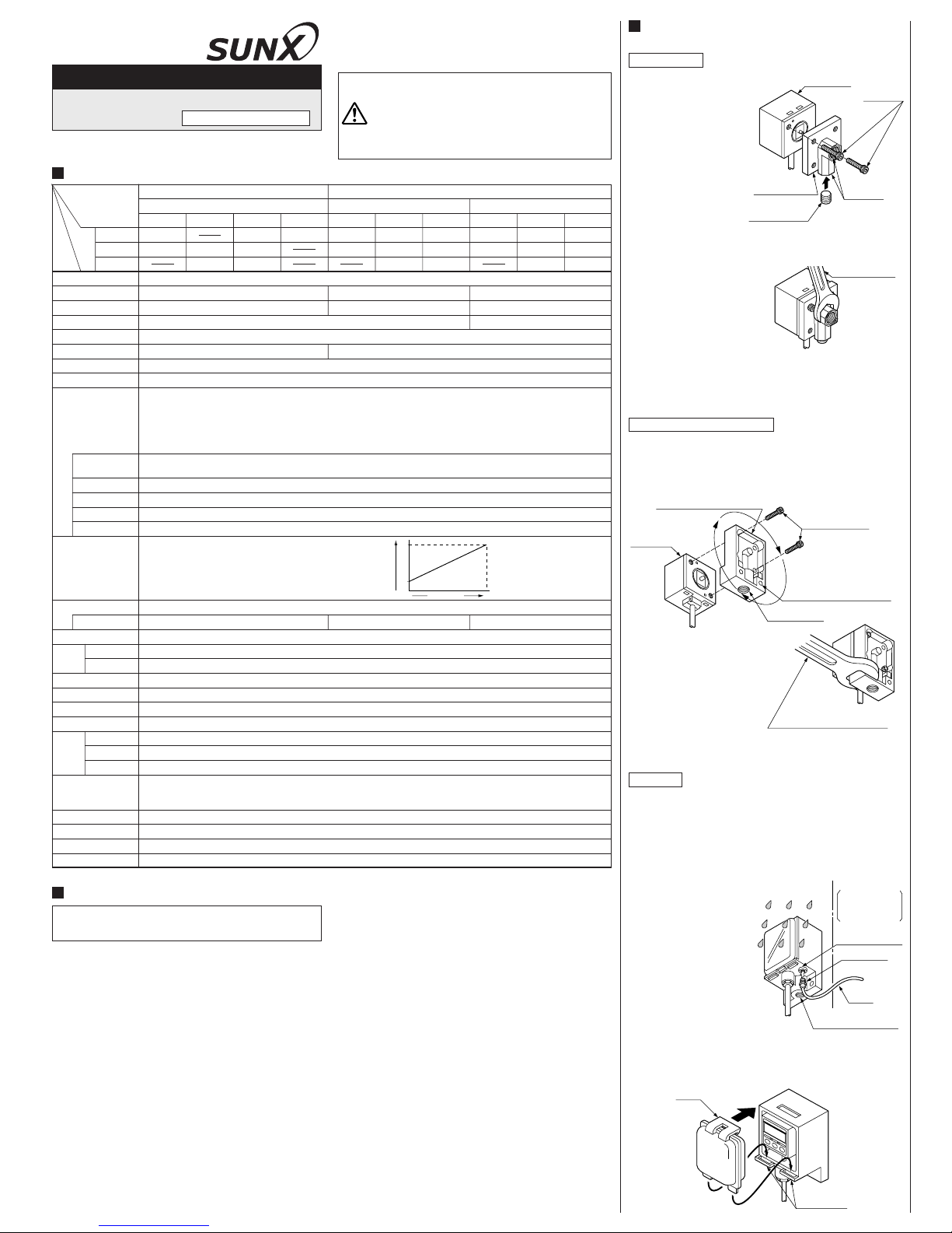
SETTING OF PRESSURE LEAD
DIRECTION AND PIPING
Standard type
䢇 Setting of pressure lead direction
• The pressure lead direc-
tion can be changed by
dismantling the pressure
port attachment and
changing the mounting
direction. The tightening
torque of the hexagonsocket-head bolt (length
9mm or less) should be
0.29N䡠m or less.
Note: Please make sure to close any unused pressure port with
the hexagon-socket-head plug supplied as accessory.
Flat type, Light weight type
䢇 Setting of pressure lead direction
• The pressure lead direction can be changed by dismantling
the pressure port attachment and changing the mounting
direction. The tightening torque of the hexagon-socket-head
bolt (length 9mm or less) should be 0.29N䡠m or less.
䢇 Piping
•
When connecting a coupling to the pressure port,
hold the pressure port
attachment with a 16mm
(Light weight type: 10mm)
spanner and make sure that
the tightening torque is
9.8N䡠m or less (Light weight
type: 1.47N䡠m or less). Also, in order to prevent any leakage,
wind a sealing tape on the coupling when connecting.
Hexagon-sockethead bolts
2-"4.3mm mounting holes
Pressure port
Pressure port attachment
Main body
16mm
(light weight type: 10mm)
spanner
Hexagonsockethead bolts
Main body
Pressure port
attachment
Hexagon-sockethead plug
Pressure
ports
䢇 Piping
• When connecting a
hexagon-socket-head plug
or coupling to the pressure
port, hold the hexagonal
part of the pressure port
with a 12mm spanner and
make sure that the
tightening torque is 9.8N䡠m
or less. Also, in order to prevent any leakage, wind a sealing
tape on the coupling when connecting.
However, sealing tape is not required for North American type
using NPTF 1/8 coupling. (Sealing tape is required if NPT1/8
coupling is used.)
12mm spanner
IP67 type
䢇 Piping for pressure measurement inlet port
• When connecting a coupling to the pressure measurement
inlet port, hold the pressure port attachment with a spanner
and make sure that the tightening torque is 9.8N䡠m or less.
Also, in order to prevent any leakage, wind a sealing tape on
the coupling when connecting.
䢇 Piping for atmospheric pressure inlet port
• If there is a possibility of
water entering into the
sensor enclosure through
the atmospheric pressure
inlet port, connect a tube to
the atmospheric pressure
inlet port through a M5
coupling and extend the
other end of the tube to a
safe place. In this case,
ensure that this end of the
tube does not get clogged.
䢇 Fitting of front cover
• Insert the bosses on the front cover into the guide holes at
the bottom of the pressure port attachment, and push in the
direction of the arrow to fit the hook.
When removing the front cover, release the hook first.
Atmospheric
pressure inlet port
Pressure measurement
inlet port
Tube
M5 coupling
Safe place,
where there is no
exposure to water
Guide holes
Hook
()
For use outside Japan
Note: Model Nos. of North American standard type having the suffix ‘-P’ are PNP output type.
MJE-DP2 No.0580-05
0
0
0
0
0
0
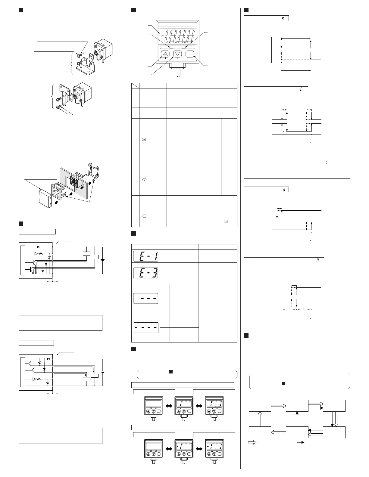
4
MOUNTING OF STANDARD TYPE SENSOR
䢇 A sensor mounting bracket MS-DPX and MS-DPX-4
(optional) may be used.
When mounting the sensor with the sensor mounting bracket,
etc., the tightening torque should be 1.2N·m or less.
䢇 Panel mounting bracket MS-DPX-2 (optional) and a front
protection cover DPX-04 (optional) are also available.
5
I/O CIRCUIT DIAGRAM
NPN output type
Tr2
Tr1
1kΩ
100mA max.
100mA max.
Users’ circuitInternal circuit
(Blue) 0V
(White) Comparative Output 2
(Black) Comparative Output 1
(Gray) Analog
voltage output
(Brown)
ⳭV
Color code
Load
Load
ZD2
ZD3
ZD1
D
12 to 24V DC
%
Ⳮ
ⳮ
Sensor circuit
Ⳮ10
ⳮ15
(Note)
Sensor mounting bracket
MS-DPX (optional)
M4 (length 6mm) pan head screw
(attached with MS-DPX)
Spring washer
(attached with MS-DPX)
D
P
2
-
2
0
–
1
0
1
.
3
k
P
a
O
U
T
2
O
U
T
1
M
O
D
E
0
A
D
J
Panel mounting bracket
MS-DPX-2 (optional)
(Suitable for 1 to 3.2mm thick panel)
D
P
2
2
0
–
1
0
1
.
3
k
P
a
O
U
T
2
O
U
T
1
M
O
D
E
0
-
A
D
J
Front protection cover
DPX-04 (optional)
Symbols…D: Reverse supply polarity protection diode
Z
D1, ZD2, ZD3: Surge absorption zener diode
Tr
1, Tr2: NPN output transistor
Note: The analog voltage output is not incorporated with a short-circuit
protection circuit. Do not directly connect a power supply or a
capacitive load. When using the analog voltage output, take
care to connect external equipment of proper input impedance.
Also, when a cable extension is used, voltage drop due to cable
resistance should be taken into account.
PNP output type
Users’ circuitInternal circuit
Color code
100mA max.
100mA max.
ZD1
ZD2
ZD3
Tr1
Load
Load
(Brown)ⳭV
(White) Comparative Output 2
(Black) Comparative Output 1
(Gray) Analog
voltage output (Note)
(Blue) 0V
12 to 24V DC
%
Ⳮ
ⳮ
Tr2
D
Sensor circuit
1kΩ
Ⳮ10
ⳮ15
Symbols…D: Reverse supply polarity protection diode
Z
D1, ZD2, ZD3: Surge absorption zener diode
Tr
1, Tr2: PNP output transistor
Note: The analog voltage output is not incorporated with a short-circuit
protection circuit. Do not directly connect a power supply or a
capacitive load. When using the analog voltage output, take
care to connect external equipment of proper input impedance.
Also, when a cable extension is used, voltage drop due to cable
resistance should be taken into account.
6
FUNCTIONAL DESCRIPTION OF
OPERATION PANEL
DP2-20
–101.3kPa
OUT2OUT1
MODE
0-ADJ
1
2
3
6
4
5
06H0129
Description Function
1
2
3
4
5
6
31/2 digit LED
display (Red)
Comparative Output 1
operation indicator
(Orange)
Comparative Output 2
operation indicator
(Green)
Increment key
()
Decrement key
()
Mode selection key
()
MODE
Displays measured pressure, settings, error messages and key-protect status.
Lights up when Comparative Output 1 is ON.
Lights up when Comparative Output 2 is ON.
• In the initial setting mode, pressing the
key changes the settable digit.
• In the Set Value 1, 2 modes, pressing
the key changes the set value to the
high pressure side in case of positive
pressure type sensor and to the high
vacuum side in case of vacuum pressure
type sensor.
•
In the sensing mode, if the key is pressed
continuously for 4 sec. or more, the display
shows peak hold value.
• In the initial setting mode, pressing the
key changes the set conditions.
• In the Set Value 1, 2 modes, pressing
the key changes the set value to the
low pressure side in case of positive
pressure type sensor and to the low
vacuum side in case of vacuum pressure
type sensor.
•
In the sensing mode, if the key is pressed
continuously for 4 sec. or more, the display
shows bottom hold value.
• Pressing the key changes the selected mode to
sensing mode, Set Value 1 (P1) set mode and Set
Value 2 (P2) set mode.
• In the sensing mode, if the key is pressed continuously for about 3 sec., key-protect can be
set/released.
• In the sensing mode, if the mode selection key is
pressed while pressing the increment key ( ) , the
initial setting mode is obtained.
In the sensing mode, if both the keys are pressed
simultaneously, zero-point adjustment is done.
7
ERROR MESSAGES
䢇 When an error occurs, take the following corrective action.
Error message Cause Corrective action
Overcurrent due to shortcircuit.
Pressure is being applied
during zero-point adjustment.
Positive
pressure
type
Vacuum
pressure
type
Positive
pressure
type
Vacuum
pressure
type
Applied pressure exceeds
the upper limit of displayable pressure range.
Applied pressure exceeds
the lower limit of displayable pressure range.
Applied pressure exceeds
the lower limit of displayable pressure range.
Applied pressure exceeds
the upper limit of displayable pressure range
.
Switch off the power supply
and check the load.
Applied pressure should be
brought within the rated
pressure range.
Applied pressure at the
pressure port should be
brought to atmospheric
pressure and zero-point
adjustment should be done
again.
8
ANALOG BAR DISPLAY
䢇
Pressure changes are displayed in an analog fashion by using LED bars.
Hence, any sudden changes in pressure can be detected at a glance.
䢇
The analog bar display shows the measured pressure, irrespective
of the pressure unit, in steps of 10% F.S. approx.
• Please refer to SETTING
2
Initial setting for the
procedure to change to analog bar display.
11
Analog bar display for positive pressure type sensor
Atm. pressure condition
Atm. pressure condition
High pressure condition
High vacuum condition
DP2-21
100kPa
OUT2OUT1
MODE
0-ADJ
DP2-21
100kPa
OUT2OUT1
MODE
0-ADJ
DP2-21
100kPa
OUT2OUT1
MODE
0-ADJ
06H0132
DP2-20
–101.3kPa
OUT2OUT1
MODE
0-ADJ
DP2-20
–101.3kPa
OUT2OUT1
MODE
0-ADJ
DP2-20
–101.3kPa
OUT2OUT1
MODE
0-ADJ
9
OUTPUT MODES & THEIR CHARACTERISTICS
Hysteresis mode ( )
䢇 The common hysteresis of the comparative outputs can be
set, as desired, with the set values.
Window comparator mode ( )
䢇
The comparative outputs can be turned ON or OFF by a pressure
which is within the pressure range set by Set Value 1 and Set Value 2.
Comparative
Output 1
Comparative
Output 2
ON
OFF
ON
OFF
0
Set Value 1 (P1) Set Value 2 (P2)
High pressure
(Positive pressure type)
High vacuum
(Vacuum pressure type)
Hysteresis
()
Hysteresis: 1 digit or more
2 digits or more when
using psi unit
Comparative
Output 1
Comparative
Output 2
ON
OFF
ON
OFF
0
Set Value 1 (P1)
Set Value 2 (P2)
High pressure
(Positive pressure type)
High vacuum
(Vacuum pressure type)
Hysteresis Hysteresis
Hysteresis: 1 digit
2 digits when
using psi unit
()
Comparative
Output 1
Comparative
Output 2
ON
OFF
ON
OFF
0
Set Value 1 (P1) Set Value 2 (P2)
High pressure
(Positive pressure type)
High vacuum
(Vacuum pressure type)
Hysteresis: 1 digit
2 digits when
using psi unit
Hysteresis
()
Dual output mode ( )
䢇 The outputs can be put to different use such as detection of
different kinds of objects, control function, alarm function etc.
Comparative
Output 1
Comparative
Output 2
ON
OFF
ON
OFF
0
Set Value 1 (P1) Set Value 2 (P2)
Set Value 3 (P3)
High pressure
(Positive pressure type)
High vacuum
(Vacuum pressure type)
Hysteresis
Hysteresis: 1 digit
2 digits when
using psi unit
()
Automatic sensitivity setting mode ( )
䢇 Using actual objects, if the pressure values for OK objects
and NG objects are input, then the sensor is automatically set
to the optimum pressure value (mid-value).
10
PRESSURE UNITS
䢇 The pressure unit can be selected as per customer’s
requirement.
䢇 In case of positive pressure type, the pressure unit can be
changed from International System of Units (SI) ‘kPa’ or
‘MPa’ to ‘kgf/cm
2
’, ‘bar’ or ‘psi’. In case of vacuum pressure
type, the pressure unit can be changed from International
System of Units (SI) ‘kPa’ to ‘kgf/cm
2
’, ‘bar’, ‘psi’, ‘mmHg’ or
‘inHg’.
•
When the pressure unit is changed, the set values and the
measured value are automatically converted.
• Please refer to SETTING
2
Initial setting for the
procedure to change the pressure unit.
11
inHg
kPa (Note)
kgf/cm
2
mmHg psi bar
: Positive pressure type: Vacuum pressure type
International System
of Units (SI)
• When operating in window comparator mode ( ) Set Value
1 (P1) and Set Value 2 (P2) should be set with a difference
of 3 digits or more. However, when the pressure unit is set
to ‘psi’, the difference should be 6 digits or more.
Note: MPa in case of DP2-22䡺, DP2-42䡺 and DP2-62䡺.
Analog bar display for vacuum pressure type sensor
Sensor mounting
bracket
MS-DPX-4 (optional)
M4 (length 6mm) pan head screw
(attached with MS-DPX-4)
Spring washer
(attached with MS-DPX-4)
Note: In case mounting brackets or screws other than the sensor
mounting bracket shown in the fiqure above are used, the length
of the screws inserted into the pressure port attachment should
be 5mm or less. If the length of the screws is longer than 5mm,
the sensor may be damaged.
<MS-DPX-4>
<
MS-DPX>

Adjust
zero-point
Commence
measurement
on completion
of setting
Enter
Set Value 1 (P1)
Set Value 2 (P2)
Set Value 3 (P3)
Set [Display],
[Output mode],
and [Unit]
DP2-20
–101.3kPa
OUT2OUT1
MODE
0-ADJ
06H0143
3rd digit 2nd digit
Change with key.
1st digit
06H0145
Unit Output mode Display
: kPa or
MPa
: kgf/cm
2
: bar
: psi
: Hysteresis
mode
: Window
comparator
mode
: Digital
display
: Analog
bar
display
: Dual output
mode
: Automatic
sensitivity
setting mode
: mmHg
: inHg
Positive
pressure type
Vacuum
pressure type
11
SETTING
䢇 If key-protect has been set, make sure to release key-
protect before operating the keys. (Please refer to KEY-
PROTECT FUNCTION for the procedure.)
䢇 The conditions which are set are stored in an EEPROM.
Kindly note that the EEPROM has a life span and its
guaranteed life is 100,000 write operation cycles.
15
1
Zero-point
adjustment
2
Initial
setting
3
Pressure
value setting
Measurement
1
Zero-point adjustment
䢇 The displayed pressure when the pressure port is left open is
adjusted to zero.
Set to sensing mode
DP2-20
–101.3kPa
OUT2OUT1
MODE
0-ADJ
• The sensor will automatically enter the
sensing mode when power is supplied.
• The figure on the left shows the display
when the pressure unit and display are set
to ‘kPa
’
and ‘digital display’, respectively.
2
Initial setting
䢇 Pressure [Unit], [Display] and [Output mode] of the
comparative outputs are set.
Set to initial setting mode
DP2-20
–101.3kPa
OUT2OUT1
MODE
0-ADJ
• In the sensing mode, press key while
pressing key.
•
Initial setting is displayed.
•
If sensor is being used for the first time,
is displayed.
Perform zero-point adjustment
DP2-20
–101.3kPa
OUT2OUT1
MODE
0-ADJ
•
Let the pressure port be at atmospheric
pressure (i.e., no applied pressure condition), and press, simultaneously, the increment and decrement keys continuously.
• is displayed and, when the finger is
released, zero-point adjustment is
completed and the sensor returns to the
sensing mode.
DP2-20
–101.3kPa
OUT2OUT1
MODE
0-ADJ
• If pressure has been applied during zeropoint adjustment, is displayed when
the keys are pressed. Bring the applied
pressure to atmospheric pressure (i.e., no
applied pressure condition) and carry out
the zero-point adjustment once again.
Set initial conditions
• The settable digit blinks.
• The settable digit changes when key
is pressed.
DP2-20
–101.3kPa
OUT2OUT1
MODE
0-ADJ
•
Change the setting of each digit as desired.
• The setting is changed when key is
pressed.
Set to sensing mode
DP2-20
–101.3kPa
OUT2OUT1
MODE
0-ADJ
• Press key.
• The
sensor returns to sensing mode after
the initial conditions have been set.
•
Since the initial conditions which have
been set are stored in an EEPROM, they
are not erased even if the power supply is
switched off.
•
The figure on the left shows the display
when the unit and display are set to ‘kPa’
and ‘digital display’, respectively.
MODE
MODE
Setting procedure
For the case when output mode is set to either the hysteresis mode
( ), window comparator mode ( ) or dual output mode ( ).
For the case when the output mode is set to automatic
sensitivity setting mode ( )
3
Setting of pressure values
䢇 [Set Value 1 (P1)] and [Set Value 2 (P2)] of the comparative
outputs are set.
䢇 Comparative outputs’[Set Value 1 (P1)], [Set Value 2 (P2)]
and [Set Value 3 (P3)] are set.
Set to sensing mode
DP2-20
–101.3kPa
OUT2OUT1
MODE
0-ADJ
• Press key.
•
The sensor returns to sensing mode after
Set Value 1 (P1) and Set Value 2 (P2)
have been set.
•
Since the values which have been set are
stored in an EEPROM, they are not
erased even if the power supply is
switched off.
MODE
• The setting of Set Value 2 (P2) with respect to Set Value 1
(P1) can only be towards the high pressure side in case of
the positive pressure type sensor and only towards the high
vacuum side in case of the vacuum pressure type sensor.
•
Set Value 1 (P1) and Set Value 2 (P2) can be made common
for all the output modes. However, when a changeover is
made to the automatic sensitivity setting mode, since Set
Value 3 (P3) has not been set, make sure to carry out the
pressure value settings for the automatic sensitivity mode.
• The setting of Set Value 2 (P2) with respect to Set Value 1
(P1) can only be towards the high pressure side in case of
the positive pressure type sensor and only towards the high
vacuum side in case of the vacuum pressure type sensor.
•
Set Value 3 (P3) is automatically set to the mid-value of Set
Value 1 (P1) and Set Value 2 (P2). However, if Set Value 1
(P1) is set to a value on the vacuum pressure side for a
positive pressure type sensor or to the positive pressure side
for a vacuum pressure type sensor, Set Value 3 (P3) is
automatically set to the mid-value of ‘zero’(atmospheric
pressure) and Set Value 2 (P2). Further, if both, Set Value 1
(P1) and Set Value 2 (P2) are set to a value on the vacuum
pressure side for a positive pressure type sensor or to the
positive pressure side for a vacuum pressure type sensor, Set
Value 3 (P3) is automatically set to ‘zero’(atmospheric
pressure).
•
The automatically set Set Value 3 (P3) can be changed manually.
• Since display of error messages is not possible during
pressure value setting in the automatic sensitivity setting
mode, make sure that the sensor is used within the rated
pressure range.
Set to Set Value 1 (P1) set mode
DP2-20
–101.3kPa
OUT2OUT1
MODE
0-ADJ
DP2-20
–101.3kPa
OUT2OUT1
MODE
0-ADJ
Displayed
alternately
• In the sensing mode, press key.
•
and Set Value 1 (P1) which is being
set are displayed alternately.
•
The figure on the left shows the display of
a vacuum pressure type sensor when the
pressure unit has been set to ‘kPa’.
Enter Set Value 1 (P1)
DP2-20
–101.3kPa
OUT2OUT1
MODE
0-ADJ
DP2-20
–101.3kPa
OUT2OUT1
MODE
0-ADJ
Displayed
alternately
• Enter using key and key.
• In case of the positive pressure type
sensor, if key is pressed once the set
value changes towards the high pressure
side by 1 digit and if key is pressed
once the set value changes towards the
low pressure side by 1 digit.
In case of the vacuum pressure type
sensor, if key is pressed once the set
value changes towards the high vacuum
side by 1 digit and if key is pressed
once the set value changes towards the
low vacuum side by 1 digit.
• If key or key is pressed continuously, the set value changes quickly.
•
If the set pressure range is exceeded,
either (upper limit exceeded) or
(lower limit exceeded) is displayed.
Set to Set Value 2 (P2) set mode
DP2-20
–101.3kPa
OUT2OUT1
MODE
0-ADJ
DP2-20
–101.3kPa
OUT2OUT1
MODE
0-ADJ
Displayed
alternately
• In the Set Value 1 (P1) set mode, press
key.
•
and Set Value 2 (P2) which is
being set are displayed alternately.
MODE
MODE
Enter Set Value 2 (P2)
DP2-20
–101.3kPa
OUT2OUT1
MODE
0-ADJ
DP2-20
–101.3kPa
OUT2OUT1
MODE
0-ADJ
Displayed
alternately
• Using key and key, enter in a
manner similar to that for entering Set
Value 1 (P1).
•
If the set pressure range is exceeded,
either (upper limit exceeded) or
(lower limit exceeded) is displayed.
• If the output mode has been set to the window comparator
mode ( ) in the initial setting mode, Set Value 1 (P1) and
Set Value 2 (P2) should be set with a difference of 3 digits
or more. However, when unit is set to ‘psi’, the difference
should be 6 digits or more.
Set to Set Value 1 (P1) set mode
DP2-20
–101.3kPa
OUT2OUT1
MODE
0-ADJ
DP2-20
–101.3kPa
OUT2OUT1
MODE
0-ADJ
Displayed
alternately
• In the sensing mode, press key.
•
and Set Value 1 (P1) which is being
set are displayed alternately.
•
The figure on the left shows the display of
a vacuum pressure type sensor when the
pressure unit has been set to ‘kPa’.
Enter Set Value 1 (P1)
DP2-20
–101.3kPa
OUT2OUT1
MODE
0-ADJ
DP2-20
–101.3kPa
OUT2OUT1
MODE
0-ADJ
Displayed
alternately
• Within the required permissible pressure
range, having created a pressure state
which is nearest to the atmospheric
pressure, press key.
•
The pressure value at the time of pressing
key is entered as Set Value 1 (P1). Set
Value 1 (P1) and are displayed
alternately.
•
If the set pressure range is exceeded,
either (upper limit exceeded) or
(lower limit exceeded) are displayed
and Set Value 1 (P1) is set automatically
to the upper or lower limit of the set
pressure range.
•
The setting of Set Value 1 (P1) can be
repeated several times in the Set Value 1
(P1) set mode.
Set to Set Value 2 (P2) set mode
DP2-20
–101.3kPa
OUT2OUT1
MODE
0-ADJ
DP2-20
–101.3kPa
OUT2OUT1
MODE
0-ADJ
Displayed
alternately
• In the Set Value 1 (P1) set mode, press
key.
•
and Set Value 2 (P2) which is being
set are displayed alternately.
MODE
MODE
Enter Set Value 2 (P2)
DP2-20
–101.3kPa
OUT2OUT1
MODE
0-ADJ
DP2-20
–101.3kPa
OUT2OUT1
MODE
0-ADJ
Displayed
alternately
• Within the required permissible pressure
range, having created a pressure state
which is nearest to the high pressure end
(for a positive pressure type sensor) or
the high vacuum end (for a vacuum
pressure type sensor), press key.
•
The pressure value at the time of pressing
key is entered as Set Value 2 (P2). Set
Value 2 (P2) and are displayed
alternately.
•
If the set pressure range is exceeded,
either (upper limit exceeded) or
(lower limit exceeded) are displayed
and Set Value 2 (P2) is set automatically
to the upper or lower limit of the set
pressure range.
•
The setting of Set Value 2 (P2) can be
repeated several times in the Set Value 2
(P2) set mode.

PRINTED IN JAPAN
http://www.sunx.co.jp/
Head Office
SUNX Limited
Phone: ⴐ81-(0)568-33-7861
FAX: ⴐ81-(0)568-33-8591
Overseas Sales Dept.
2431-1 Ushiyama-cho, Kasugai-shi, Aichi,
486-0901, Japan
Phone: ⴐ81-(0)568-33-7211
FAX: ⴐ81-(0)568-33-2631
12
PROCEDURE FOR CHECKING SET VALUES
Set to Set Value 3 (P3) set mode
DP2-20
–101.3kPa
OUT2OUT1
MODE
0-ADJ
DP2-20
–101.3kPa
OUT2OUT1
MODE
0-ADJ
Displayed
alternately
• In the Set Value 2 (P2) set mode, press
key.
•
and the automatically set Set Value
3 (P3) are displayed alternately.
•
In case
Set Value 1 (P1) = ⳮ50.0kPa
Set Value 2 (P2) = ⳮ100.0kPa
then
Set Value 3 (P3) =
ⳮ50.0Ⳮ(ⳮ100.0)
= ⳮ75.0kPa
2
Digits smaller than the displayed digits
are discarded.
MODE
In case Set Value 3 (P3) is to be changed
• The automatically set Set Value 3 (P3) can be manually changed to
a value between Set Value 1 (P1) and Set Value 2 (P2). However
Set Value 3 (P3) cannot be set to a value on the vacuum pressure
side for a positive pressure type sensor or to the positive pressure
side for a vacuum pressure type sensor.
Set to sensing mode
DP2-20
–101.3kPa
OUT2OUT1
MODE
0-ADJ
• Press key.
•
The sensor returns to the sensing mode
after Set Value 1 (P1), Set Value 2 (P2)
and Set Value 3 (P3) have been set.
•
Since the values which have been set are
stored in an EEPROM, they are not erased
even if the power supply is switched off.
MODE
䢇
The conditions which have been set in the initial setting and the
pressure settings can be checked by the following procedure.
• Please note that if any key, except key, is pressed in any
setting mode, the set conditions shall get changed.
MODE
Procedure to check initial conditions
Procedure to check set values
Set to sensing mode Set to sensing mode
Press key
while pressing
key.
Press key.
Sensor enters initial setting mode
Sensor enters Set Value 1 (P1) set mode
•
Initial conditions which have
been set are displayed and can
be checked.
•
Set Value 1 (P1) which has
been set is displayed and can
be checked.
Sensor returns to sensing mode
Sensor enters Set Value 2 (P2) set mode
•
Set Value 2 (P2) which has
been set is displayed and can
be checked.
Sensor enters Set Value 3 (P3) set mode
•
Set Value 3 (P3) which has
been set is displayed and can
be checked.
Sensor returns to sensing mode
MODE
Press key.
In case of auto-
matic sensitivity
setting mode only
MODE
MODE
Press key.
MODE
Press key.
MODE
Press key.
MODE
13
CONVERSION OF PRESSURE UNITS
䢇 In the DP2 series, the conversion to different units is automatically done on changing the setting of the pressure unit. However,
this conversion can also be obtained by multiplying the values by the coefficients given in the following table.
•
For example, if 2kPa is to be expressed in kgf/cm2, since 1kPa=1.01972⳯10ⳮ2kgf/cm2, 2kPa becomes 2⳯1.01972⳯10ⳮ2c 0.020kgf/cm
2
Conversion procedure
Conversion table for pressure units
kPa MPa kgf/cm
2
bar psi
mmHg
inHg atm
(Torr)
1kPa 1 1
⳯10
ⳮ3
1.01972⳯10ⳮ21⳯10ⳮ21.45038⳯10ⳮ17.50062 0.2953
9.86923⳯10
ⳮ3
1MPa 1⳯10
3
1 1.01972⳯10 1⳯10 1.45038⳯1027.50062⳯1030.2953⳯1039.86923
1kgf/cm
2
9.80665⳯10
9.80665⳯10
ⳮ2
1
9.80665⳯10ⳮ11.42234⳯10
7.35559⳯1022.8959⳯10
9.67841⳯10
ⳮ1
1bar 1⳯10
2
1⳯10
ⳮ1
1.01972 1 1.45038⳯10
7.50062⳯1022.953⳯10
9.86923⳯10
ⳮ1
1psi 6.89473
6.89473⳯10ⳮ37.03065⳯10ⳮ26.89473⳯10
ⳮ2
1 5.17147⳯10 2.036
6.80457⳯10
ⳮ2
1mmHg
1.33322⳯10ⳮ11.33322⳯10ⳮ41.35951⳯10ⳮ31.33322⳯10ⳮ31.93368⳯10
ⳮ2
1
3.9370⳯10ⳮ21.31579⳯10
ⳮ3
(
1Torr)
1inHg 3.3864
3.3864⳯10ⳮ33.4531⳯10ⳮ23.3864⳯10ⳮ20.4912 2.5400⳯10 1
3.342⳯10
ⳮ2
1atm
1.01325⳯1021.01325⳯10ⳮ11.03323 1.01325 1.46960⳯10
7.60000⳯1022.9921⳯10 1
14
PEAK HOLD & BOTTOM HOLD FUNCTIONS15KEY-PROTECT FUNCTION
䢇 Peak hold and bottom hold functions enable the display of the
peak value (maximum pressure value in case of the positive
pressure type sensor and maximum vacuum pressure value
in case of the vacuum pressure type sensor) and the bottom
value (minimum pressure value in case of the positive
pressure type sensor and minimum vacuum pressure value in
case of the vacuum pressure type sensor) of the varying
measured pressure.
䢇 These functions are convenient for finding the pressure
variation range or for determining the reference for pressure
settings.
䢇 Key-protect is a function which prevents any unintentional
change in the conditions which have been entered in each
setting mode by making the sensor not to respond to the key
operations.
16
LABEL FOR CHANGE IN PRESSURE UNIT
䢇 When a pressure unit other than ‘kPa’ or ‘MPa’ has been
selected in the initial setting mode, the label (supplied as
accessory) which corresponds to the selected unit should be
stuck at the position shown in the figure below.
• Please note that the peak value and the bottom value data
is erased when it is no longer displayed.
• The response time of the comparative outputs becomes
slower during the peak hold and bottom hold display.
• Since the key-protect information is stored in an EEPROM,
it is not erased even if the power supply is switched off.
• Please take care to remember if the key-protect function
has been set.
Peak hold display
Initiating peak hold display
Setting of key-protect
DP2-20
–101.3kPa
OUT2OUT1
MODE
0-ADJ
DP2-20
–101.3kPa
OUT2OUT1
MODE
0-ADJ
Displayed
alternately
DP2-20
–101.3kPa
OUT2OUT1
MODE
0-ADJ
• In the sensing mode, keep key pressed
until is displayed. (4 sec. approx.)
When the finger is released after is
displayed, the peak value and are
displayed alternately.
•
If the applied pressure exceeds the
displayable pressure range, error
message ( or ) and are
displayed alternately. In this case, bring
back the applied pressure to within the
rated pressure range.
•
The figure on the left shows the display of
a vacuum type sensor when the pressure
unit has been set to ‘kPa’.
DP2-20
–101.3kPa
OUT2OUT1
MODE
0-ADJ
• In the sensing mode, press key
continuously for about 3 sec. and release
it immediately when is displayed.
•
Key-protect is set and the sensor returns
to the sensing mode.
MODE
Ending peak hold display
• Press key.
[• Sensor returns to sensing mode.]
Bottom hold display
Initiating bottom hold display
DP2-20
–101.3kPa
OUT2OUT1
MODE
0-ADJ
DP2-20
–101.3kPa
OUT2OUT1
MODE
0-ADJ
Displayed
alternately
DP2-20
–101.3kPa
OUT2OUT1
MODE
0-ADJ
• In the sensing mode, keep key pressed
until is displayed. (4 sec. approx.)
When the finger is released after is
displayed, the bottom value and are
displayed alternately.
•
If the applied pressure exceeds the
displayable pressure range, error
message or and are
displayed alternately. In this case, bring
back the applied pressure to within the
rated pressure range.
•
The figure on the left shows the display of
a vacuum type sensor when the pressure
unit has been set to ‘kPa’.
Ending bottom hold display
• Press key.
[• Sensor returns to sensing mode.]
• When the keys are to be operated, make sure that keyprotect is released.
Release of key-protect
DP2-20
–101.3kPa
OUT2OUT1
MODE
0-ADJ
• In the sensing mode, press key
continuously for about 3 sec. and release
it immediately when is displayed.
•
Key-protect is released and the sensor
returns to the sensing mode.
MODE
Pressure unit label (accessory)
DP2-20
–101.3kPa
OUT2OUT1
MODE
0-ADJ
Comparative
Output 1
Comparative
Output 2
ON
OFF
ON
OFF
0
Set Value 1 (P1) Set Value 2 (P2)
Set Value 3 (P3)
High pressure
(Positive pressure type)
High vacuum
(Vacuum pressure type)
Hysteresis
Changeable
range
Hysteresis: 1 digit
2 digits when
psi unit is used
()
DP2-20
–101.3kPa
OUT2OUT1
MODE
0-ADJ
DP2-20
–101.3kPa
OUT2OUT1
MODE
0-ADJ
Displayed
alternately
• Enter using key and key.
• In case of a positive pressure type
sensor, if key is pressed once, the set
value changes towards the high pressure
side by 1 digit and if key is pressed
once, the set value changes towards the
low pressure side by 1 digit.
In case of a vacuum pressure type
sensor, if key is pressed once the set
value changes towards the high vacuum
side by 1 digit and if key is pressed
once the set value changes towards the
low vacuum side by 1 digit.
• If key or key is pressed continuously, the set value changes quickly.
•
If the set pressure range is exceeded,
either (upper limit exceeded) or
(lower limit exceeded) is displayed.
(
)
 Loading...