


 Loading...
CX-400
Instruction Manual
Bedienungsanleitung
Manual de Instrucciones
Manuel d’instructions
Manuale di istruzione
<![endif]>EN
<![if ! IE]><![endif]>DE
<![if ! IE]><![endif]>ES
<![if ! IE]><![endif]>FR
<![if ! IE]><![endif]>IT
INSTRUCTION MANUAL
Compact Photoelectric Sensor
CX-400 Series
MEUML-CX400 V1.0 Thank you very much for using SUNX products. Please read this Instruction Manual carefully and thoroughly for the correct and optimum use of this product. Kindly keep this manual in a convenient place for quick reference.
 WARNING
• Never use this product as a sensing device for personnel protection.
• In case of using sensing devices for personnel protection, use products which meet laws and standards, such as OSHA, ANSI or IEC etc., for personnel protection applicable in each region or country.
1 CAUTIONS
Make sure to carry out wiring with the power OFF. Incorrect wiring will damage the sensor.
Verify that the supply voltage including the ripple is within the rating.
If power is supplied from a commercial switching regulator, ensure that the frame ground (F.G.) terminal of the power supply is connected to an actual ground.
In case noise generating equipment (switching regulator, inverter motor, etc.) is used in the vicinity of this product, connect the frame ground (F.G.) terminal of the equipment to an actual ground.
Do not run the wires together with high-voltage lines or power lines or put them in the same raceway. This can cause malfunction due to induction. Do not use during the initial transient time (50ms) after the power supply is switched on.
This sensor is suitable for indoor use only.
You can extend the cable up to 100m max. with 0.3mm2 or more cable. However, in order to reduce noise, make the wiring as short as possible. Do not apply stress directly to the sensor cable joint by forcibly bending or pulling.
Do not use this sensor in places having excessive vapor, dust, etc., or where it may come in direct contact with water or corrosive gas.
Take care that the sensor does not come in direct contact with water, oil, grease, or organic solvents such as thinners, etc.
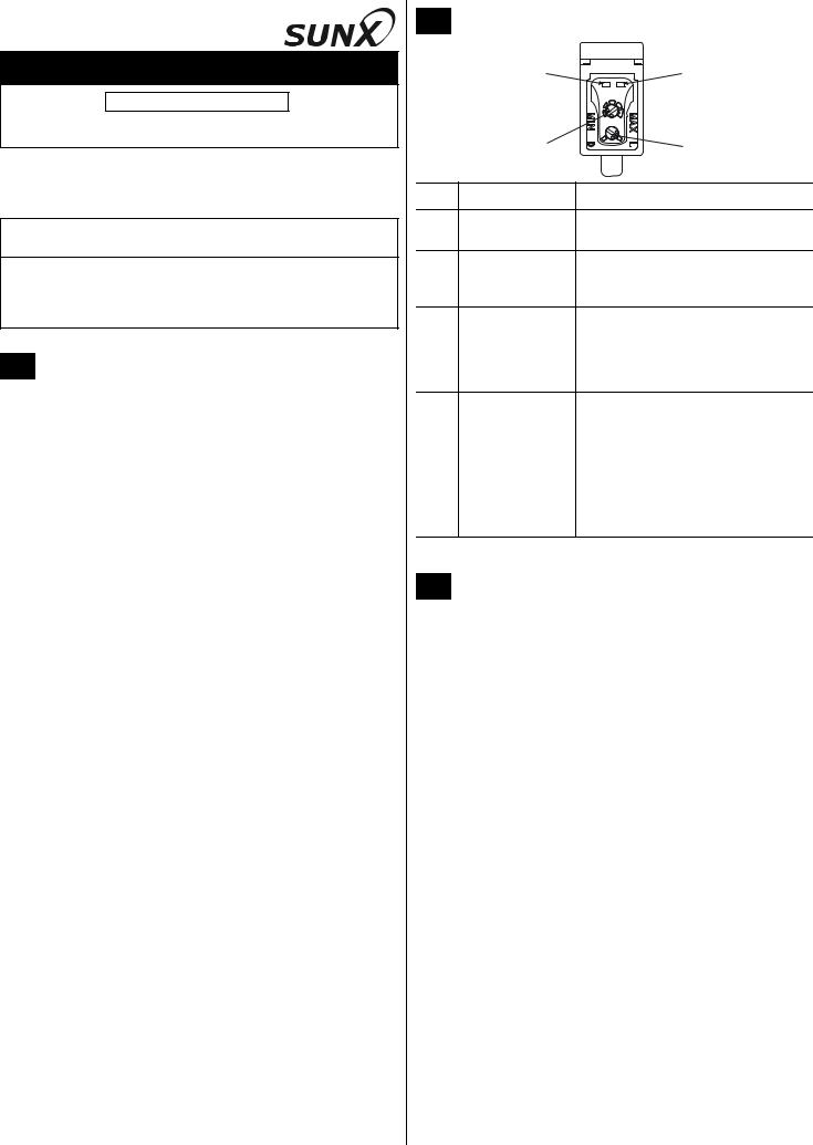
2 PART NAMES
|
1 |
2 |
|
3 |
4 |
|
|
|
No. |
Part |
Description |
1 |
Stability indicator |
Lights up under the stable Light or stable |
|
(green) |
Dark condition. |
2 |
Operation indicator |
• Reflective type, thru-beam receiver: |
|
(orange) |
lights up when the sensor output is ON. |
|
|
• Thru-beam emitter: power indicator. |
3 |
Sensitivity adjuster |
Reflective type, thru-beam receiver: |
|
|
sensing range increased when turned |
|
|
clockwise. |
|
|
See “SENSITIVITY ADJUSTMENT” on |
|
|
page 3. |
4 |
Operation mode |
Reflective type, thru-beam receiver: |
|
switch |
• L: Light-ON |
|
|
Light-ON mode is obtained when the |
|
|
operation mode switch is turned fully |
|
|
clockwise (L). |
|
|
• D: Dark-ON |
|
|
Dark-ON mode is obtained when the |
|
|
operation mode switch is turned fully |
|
|
counterclockwise (D). |
3 CONNECTOR CABLES
Connector cables for the M12 pigtailed type
Type |
Model no. |
Cable length |
|
|
|
|
|
2-core type |
CN-22-C2 |
2m |
|
|
|
||
CN-22-C5 |
5m |
||
|
|||
|
|
|
|
4-core type |
CN-24-C2 |
2m |
|
|
|
||
CN-24-C5 |
5m |
||
|
|||
|
|
|
|
Connector cables for the M8 connector type |
|
||
|
|
|
|
Type |
Model no. |
Cable length |
|
|
|
|
|
Straight type |
UZZ80820 |
2m |
|
|
|
||
UZZ80850 |
5m |
||
|
|||
|
|
|
|
Elbow type |
UZZ80821 |
2m |
|
|
|
||
UZZ80851 |
5m |
||
|
|||
|
|
|
|
Two sets of cables are required for the thru-beam type sensor.
1
4 I/O CIRCUIT DIAGRAMS
The following symbols are used in this section.
Symbol |
Meaning |
|
|
|
|
D |
Reverse supply polarity protection diode |
|
|||
ZD |
Surge absorption zener diode |
|
|
||
Tr |
NPN / PNP output transistor |
|
|
||
Pin assignment |
|
|
|
||
M12 pigtailed type |
Terminal name |
M8 connector type |
|||
|
1 |
1) +V |
2 |
4 |
|
2 |
2) Not connected |
||||
|
|
|
|||
|
|
3) 0V |
|
|
|
|
|
4) Output (see note) |
|
|
|
3 |
4 |
|
1 |
3 |
|
|
|
|
|
||
Only the thru-beam receiver incorporates the output.
NPN output type
Color code of cable with connector
|
D |
| <![if ! IE]> <![endif]>circuit |
|
| <![if ! IE]> <![endif]>Sensor |
Tr |
ZD |
(Brown / 1) +V
(Black / 4) |
Load |
Output (note)
100mA max.
(Blue / 3) 0V
+ |
12 to 24V DC |
- |
±10% |
Internal circuit

 Users' circuit
Only the thru-beam receiver incorporates the output.
PNP output type
Color code of cable with connector
| <![if ! IE]> <![endif]>circuit |
ZD |
|
Tr |
||
| <![if ! IE]> <![endif]>Sensor |
||
|
||
|
D |
(Brown / 1) +V
100mA max.
(Black / 4)
Output (note) Load
(Blue / 3) 0V
+12 to 24V DC
-±10%
Internal circuit

 Users' circuit
Only the thru-beam receiver incorporates the output.
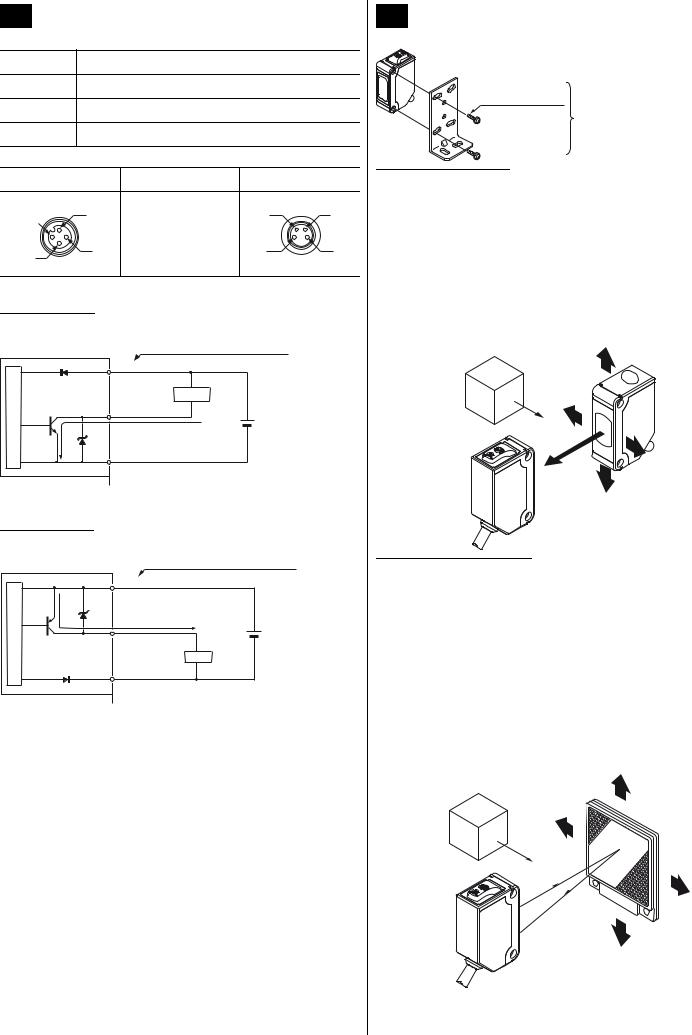
5 MOUNTING AND ADJUSTING
Mount the sensor with a tightening torque of 0.5N·m or less.
12mm M3 screws with washers
Sensor mounting bracket (optional)
Thru-beam type sensor
1 Set the operation mode switch to the Light-ON mode position (L side).
2Placing the emitter and the receiver face to face along a straight line. Move the emitter up, down, left and right to determine where light is received with the help of the receiver’s operation indicator (orange). Set the emitter in the middle of this area.
3 Adjust the angle of the emitter by twisting it up, down, left and right. 4 In a similar manner, adjust the angle of the receiver.
5 Check that the stability indicator (green) lights up.
6Choose the desired operation mode, Light-ON or Dark-ON, with the operation mode switch.
Object to be sensed
Emitter
Receiver
Retroreflective type sensor
Make sure to mount the sensor and the reflector at least 0.1mm apart.
1 Set the operation mode switch to the Light-ON mode position (L side).
2Placing the sensor and the reflector face to face along a straight line. Move the reflector up, down, left and right to determine where light is received the help of the operation indicator (orange). Set the reflector in the middle of this area.
3 Adjust the angle of the reflector by twisting it up, down, left and right. 4 In a similar manner, adjust the angle of the sensor.
5 Check that the stability indicator (green) lights up.
6Choose the deisred operation mode, Light-ON or Dark-ON, with the operation mode switch.
Object to be sensed
Reflector
Sensor
2

6 SENSITIVITY ADJUSTMENT
To understand sensitivity adjustment, you must first understand the difference between the “light received” and the “dark” condition.
Do not confuse the “light received” and “dark” condition with the operation modes “Light-ON” and “Dark-ON”!
|
Light received condition |
|
Dark condition |
||
| <![if ! IE]> <![endif]>Thru-beam |
Emitter |
Receiver |
|
Object to |
|
|
|
Emitter |
be sensed |
Receiver |
|
|
|
|
|
|
|
| <![if ! IE]> <![endif]>Retroreflective |
Sensor |
Reflector |
Sensor |
Object to |
Reflector |
|
|
be sensed |
|||
|
|
|
|
|
|
| <![if ! IE]> <![endif]>Diffuse reflective |
Sensor |
Object to |
Sensor |
|
|
be sensed |
|
|
|
||
|
|
|
|
||
|
|
|
|
|
|
Relationship between output and indicators
Light-ON |
Dark-ON |
Stability |
Operation |
Output |
Sensing |
Output |
Operation |
Stability |
|
indicator |
indicator |
condition |
indicator |
indicator |
|||
|
|
||||||
|
|
|
Stable |
|
|
|
|
|
|
ON |
light |
OFF |
|
|
|
|
|
Unstable |
|
|
|||
|
|
|
|
|
|
||
|
|
|
light |
|
|
|
|
|
|
|
Unstable |
|
|
|
|
|
|
OFF |
dark |
ON |
|
|
|
|
|
Stable |
|
|
|||
|
|
|
|
|
|
||
|
|
|
dark |
|
|
|
|
= lit, |
= unlit |
|
|
|
|
|
Use a standard screwdriver and turn the adjuster slowly. Using excessive force will damage the adjuster.
This procedure assumes that “Light-ON” is set for the operation mode.
If “Dark-ON” is the operation mode, the output will behave the other way around!
Sensitivity
Step Description
adjuster
1 |
|
Turn the sensitivity adjuster fully counter- |
|
|
clockwise to the minimum sensitivity posi- |
|
|
tion, MIN. |
2 |
|
In the “light received” condition, turn the |
|
|
sensitivity adjuster slowly clockwise to find |
|
|
point A where the sensor output turns |
|
|
ON.*1 |
3 |
|
In the “dark” condition, turn the sensitivity |
|
|
adjuster clockwise until the sensor output |
|
|
turns ON.*1 |
|
|
Turn it back slowly to confirm point B, |
|
|
where the sensor output just turns OFF.*1 |
|
|
If the sensor output does not turn ON even |
|
|
when the sensitivity adjuster is turned fully |
|
|
clockwise, point B is the position at MAX. |
4 |
Optimum positio |
The position exactly between points A and |
|
B is the optimum sensing position. |
|
|
|
*1Remember, this only applies if the operation mode is Light-ON.
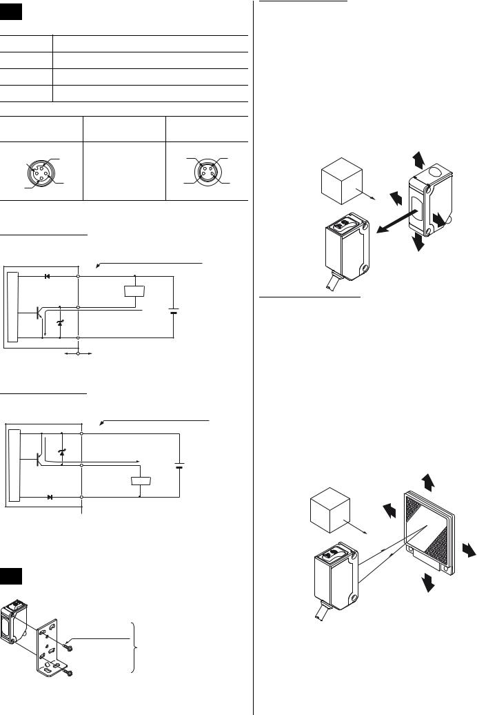
7AUTOMATIC INTERFERENCE PREVENTION FUNCTION
This function is not available for the thru-beam type sensor. See “INTERFERENCE PREVENTION FILTERS” on page 4.
The automatic interference prevention function allows you to mount up to two sets of sensors next to each other.
2 sensors mounted closely together
3
8RETROREFLECTIVE TYPE SENSOR WITH POLARIZING FILTERS
As light is polarized by a transparent film or membrane, CX-491 may not detect an object covered or wrapped by transparent film. Such objects include, for example:
Can wrapped by clear film
Aluminum sheet covered by plastic film
Gold or silver (glossy) labels or wrapping paper In such cases, take the following steps.
1 Tilt the sensor with respect to the object to be sensed. 2 Reduce the sensitivity.
3 Increase the distance between the sensor and the object to be sensed.
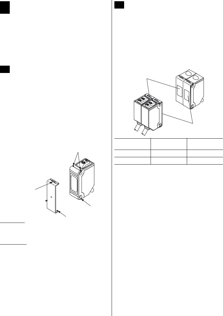
9SLIT MASKS
The slit mask is only available for the thru-beam type sensor.
Optional slit masks help the sensor detect small objects. However, the sensing range is reduced.
Type |
Model no. |
Slit size |
|
|
|
|
OS-CX-05 |
= 0.5mm |
|
|
|
Round slit mask |
OS-CX-1 |
= 1mm |
|
|
|
|
OS-CX-2 |
= 2mm |
|
|
|
|
OS-CX-05 x 6 |
0.5 × 6mm |
|
|
|
Rectangular slit mask |
OS-CX-1 x 6 |
1 × 6mm |
|
|
|
|
OS-CX-2 x 6 |
2 × 6mm |
|
|
|
3
4
Slit mask 
2
1
How to mount
1 Insert the hook (1) into the bottom groove (2).
2Press the slit mask until it snaps into the grooves (3) on the top of the main unit.
How to remove
1 Insert a screw driver into the tab (4). 2 Lift and remove carefully.
10INTERFERENCE PREVENTION FILTERS
Interference prevention filters are only available for the thru-beam type sensor.
By mounting interference prevention filters, two sets of thru-beam type sensors can be mounted close together. However, the sensing range is reduced.
The filters can be mounted using the same method as for slit masks. For details, see page 4, section 9, SLIT MASKS.
For interference prevention to work, the following conditions must be met.
The two sets of sensors must be fitted with different types of interference prevention filters.
Filters must be mounted on emitters and receivers.
PF-CX4-H
|
|
PF-CX4-V |
|
Model no. |
Direction of thru- |
Color of the bracket |
|
beam axis |
|||
|
|
||
PF-CX4-H |
Horizontal |
Light brown |
|
PF-CX4-V |
Vertical |
Silver |
The model no. is not shown on the interference prevention filters. Take care when mounting them on the sensors.
4

11 SPECIFICATIONS
|
|
|
|
Retroreflective type with |
|
Diffuse reflective |
Narrow view |
||
|
|
Thru-beam |
|
|
|
|
|
||
|
|
|
|
Short sensing |
|
Long sensing |
|||
|
|
|
polarizing filter*1 |
|
|
reflective |
|||
|
|
|
|
|
|
||||
Item |
|
|
|
|
range |
|
range |
|
|
|
|
|
|
|
|
|
|
||
|
|
CX-411 (NPN)*2 |
|
CX-491 (NPN)*2 |
|
CX-421 (NPN)*2 |
|
CX-422 (NPN)*2 |
CX-423 (NPN)*2 |
|
|
CX-411-P (PNP)*2 |
|
CX-491-P (PNP)*2 |
|
CX-421-P (PNP)*2 |
|
CX-422-P (PNP)*2 |
CX-423-P (PNP)*2 |
Sensing range |
10m |
|
3m*3 |
|
300mm*4 |
|
800mm*4 |
70 to 200mm*4 |
|
|
|
12mm or more opaque |
|
50mm or more opaque, |
|
Opaque, translucent or specular |
Opaque, translucent |
||
Object to be sensed |
object |
|
translucent or specular |
|
|
|
|
or transparent object |
|
|
|
object*3 |
|
|
|
|
(Min. 0.5mm |
||
|
|
|
|
|
|
|
|
||
|
|
|
|
|
|
|
|
|
copper wire) |
|
|
|
|
|
|
|
|||
Repeatability |
0.5mm or less |
|
1mm or less |
0.5mm or less |
|||||
(perpendicular to sensing axis) |
|
|
|
|
|
|
|
|
|
|
|
|
|
|
|
|
|||
Supply voltage |
|
|
12 to 24V DC ±10% Ripple P-P 10% or less |
|
|||||
|
|
|
|
|
|
|
|
|
|
Current consumption |
Emitter: 20mA or less |
|
20mA or less |
|
25mA or less |
20mA or less |
|||
Receiver: 20mA or less |
|
|
|
|
|
|
|
||
|
|
|
|
|
|
|
|
|
|
|
|
|
|
|
|
|
|
|
|
|
|
NPN output type |
|
|
|
PNP output type |
|
||
|
|
• NPN open-collector transistor |
|
• PNP open-collector transistor |
|
||||
|
|
• Maximum sink current: 100mA |
|
• Maximum source current: 100mA |
|
||||
Output |
• Applied voltage: 30V DC or less (between output and |
|
• Applied voltage: 30V DC or less (between output and +V) |
||||||
|
|
0V) |
|
|
|
• Residual voltage: 1V or less (at 100mA source current), 0.4V or |
|||
|
|
• Residual voltage: 1V or less (at 100mA sink current), |
|
less (at 16mA source current) |
|
||||
|
|
0.4V or less (at 16mA sink current) |
|
|
|
|
|
||
|
|
|
|
|
|
|
|
|
|
|
Output |
|
|
Light-ON or Dark-ON |
|
|
|||
|
operation |
|
|
|
|
|
|
|
|
|
|
|
|
|
|
|
|
||
|
Short- |
|
|
|
Incorporated |
|
|
||
|
circuit |
|
|
|
|
|
|
|
|
|
protection |
|
|
|
|
|
|
|
|
|
|
|
|
|
|
|
|
|
|
Response time |
|
|
|
1ms or less |
|
|
|||
|
|
||||||||
Operation indicator |
Orange LED, lights up when the output is ON. Thru-beam type sensor: located on the receiver. |
||||||||
|
|
|
|||||||
Stability indicator |
Green LED, lights up under stable light received condition or stable dark condition. Thru-beam type sensor: located on the |
||||||||
|
|
|
|
receiver |
|
|
|||
|
|
|
|
|
|
|
|
||
|
|
|
|
|
|
|
|
|
|
|
|
Green LED, lights up |
|
|
|
|
|
|
|
Power indicator |
when the power is ON. |
|
|
_____________________ |
|
||||
|
|
Located on the emitter |
|
|
|
|
|
|
|
|
|
|
|
|
|
|
|
|
|
Sensitivity adjuster |
|
|
|
Available. |
|
|
|||
|
|
|
|
|
|
|
|||
Automatic |
_____*5 |
|
Incorporated, two sets of sensors can be mounted close together. |
||||||
interference |
|
|
|
|
|
|
|
|
|
prevention function |
|
|
|
|
|
|
|
|
|
|
|
|
|
|
|
|
|
|
|
Protection |
|
|
|
IP67 (IEC) |
|
|
|||
|
|
|
|
||||||
Ambient temperature |
|
-25 to +55°C (No dew condensation or icing allowed), Storage: -30 to +70°C |
|
||||||
|
|
|
|
|
|
||||
Ambient humidity |
|
|
35 to 85% RH, Storage: 35 to 85% RH |
|
|
||||
|
|
|
|
|
|
|
|||
Emitting element |
Red LED (modulated) |
|
Infrared LED (modulated) |
Red LED |
|||||
|
|
|
|
|
|
|
(modulated) |
||
|
|
|
|
|
|
|
|
|
|
|
|
|
|
|
|
|
|||
Material |
|
|
Enclosure: PBT, Lens: Acrylic, Indicator cover: Acrylic |
|
|||||
|
|
|
|||||||
Cable |
0.2mm2 3-core (thru-beam type sensor emitter: 2-core) cabtyre cable, 2m long |
|
|||||||
Weight |
Emitter: 45g approx. |
|
|
|
50g approx. |
|
|||
Receiver: 50g approx. |
|
|
|
|
|
|
|
||
|
|
|
|
|
|
|
|
|
|
|
|
|
|
|
|
|
|
|
|
Accessory |
_____ |
|
RF-230 (Reflector): 1 pc. |
|
|
|
_____ |
|
|
|
|
|
|
|
|
|
|
|
|
*1The retroreflective type sensor with polarizing filters may not stably detect specular or glossy objects through transparent film since light is polarized by the transparent film. For details, see page 4, section 8, RETROREFLECTIVE TYPE SENSOR WITH POLARIZING FILTERS.
*2Model nos. with the suffix -J indicate the M12 pigtailed type. The suffix -Z indicates the M8 connector type. *3The sensing range and the sensing object for the retroreflective type sensor is specified for the RF-230 reflector.
5

*4The sensing range of the diffuse reflective type sensor and the narrowview reflective type sensor is specified for white non-glossy paper (200 x 200mm). *5By mounting interference prevention filters, two sets of the sensors can be mounted close together. For details, see page 4, section 10, INTERFERENCE
PREVENTION FILTERS.
SUNX Limited |
URL: sunx.jp |
Overseas Sales Dept. (Head Office)
2431-1 Ushiyama-cho, Kasugai-shi, Aichi, 486-0901, Japan
Phone: +81-(0)568-33-7861 FAX: +81-(0)568-33-8591
Europe Headquarter: Panasonic Electric Works Europe AG www.panasonic-electric-works.com
6 Rudolf-Diesel-Ring 2, D-83607 Holzkirchen, Germany Phone: +49-8024-648-0

BEDIENUNGSANLEITUNG
Kompakter Optosensor
Serie CX-400
MEUML-CX400 V1.0 Danke, dass Sie sich für ein SUNX-Produkt entschieden haben. Bitte lesen Sie diese Bedienungsanleitung, für die optimale Verwendung dieses Produkts, sorgfältig durch. Heben Sie diese Bedienungsanleitung zum Nachlesen griffbereit auf.
 WARNUNG
• Benutzen Sie dieses Produkt nicht zum Schutz von Personen.
• Wenn Sie einen Sensor zum Personenschutz verwenden möchten, sollten Sie Produkte verwenden, die den diesbezüglichen Gesetzen und Standards, wie etwa OSHA, ANSI oder IEC, entsprechen .
1 VORSICHTSMASSNAHMEN
Führen Sie die Verdrahtung nur bei ausgeschalteter Stromversorgung durch.
Falsche Verdrahtungen können den Sensor beschädigen.
Die Spannungsversorgung muss innerhalb der angegebenen Werte inklusive Restwelligkeit liegen.
Wird der Strom von einem handelsüblichen Schaltregler bereitgestellt, stellen Sie sicher, dass die Geräteerde (F.G.) der Spannungsversorgung an eine Schutzerde angeschlossen ist.
Falls elektrische Bauteile (Schaltregler, Frequenzumrichter, etc.) in der Nähe des Produkts verwendet werden, die Störstrahlungen erzeugen, müssen Sie den Erdungsanschluss der Bauteile an eine vorhandene Schutzerde anschließen.
Verlegen Sie die Kabel nicht zusammen mit Hochspannungsleitungen und legen Sie diese nicht in dieselbe Kabelschiene. Damit keine Spannungen induziert werden, dürfen sich in der Nähe der Leitungen keine Starkstromkabel oder Hochspannungsleitungen befinden. Dies kann zu Fehlfunktionen führen.
Während des Initialisierungsvorgangs (50ms nach dem Einschalten der Spannungsversorgung) dürfen keine Einstellungen und Messungen erfolgen.
Dieser Sensor darf nur in Innenräumen verwendet werden.
Das Kabel mit einer Stärke von mindestens 0,3mm2 darf bis maximal 100m verlängert werden. Um Störstrahlungen zu vermeiden, sollte das Kabel jedoch möglichst kurz gehalten werden.
Beanspruchen Sie die Kabelverbindungsstelle des Sensors nicht durch gewaltsames Verbiegen oder Ziehen.
Montageorte mit übermäßig viel Dampf, Staub, etc. sind ungeeignet. Vermeiden Sie auch, dass der Sensor korrodierenden Dämpfen ausgesetzt wird.
Der Sensor darf ferner nicht mit Wasser, Öl, Fett oder organischen Lösungsmitteln, wie Verdünner, in Berührung kommen.
2 BAUTEILE
|
1 |
2 |
|
3 |
4 |
|
|
|
Nr. |
Bauteil |
Beschreibung |
1 |
Stabilitätsanzeige |
Leuchtet, wenn die Hell-/Dunkelbedingun- |
|
(grün) |
gen stabil sind. |
2 |
Betriebsanzeige |
• Empfänger der Reflexions- |
|
(orange) |
Lichtschranke, Einweg- |
|
|
Lichtschranke: Leuchtet, wenn der |
|
|
Ausgang auf EIN schaltet. |
|
|
• Sender der Einweg-Lichtschranke: |
|
|
Stromversorgungsanzeige. |
3 |
Empfindlich- |
Empfänger der Reflexions-Licht- |
|
keitspotenziometer |
schranke, Einweg-Lichtschranke: Dre- |
|
|
hen im Uhrzeigersinn erhöht die |
|
|
Reichweite. |
|
|
Siehe “EMPFINDLICHKEIT ANPASSEN” |
|
|
auf Seite 3. |
4 |
Hell-Dunkel-Schal- |
Empfänger der Reflexions-Licht- |
|
ter |
schranke, Einweg-Lichtschranke: |
|
|
• L: Hell-EIN |
|
|
Der Modus Hell-EIN wird aktiviert, wenn |
|
|
Sie den Hell-Dunkel-Schalter im |
|
|
Uhrzeigersinn bis zum Anschlag drehen |
|
|
(L). |
|
|
• D: Dunkel-EIN |
|
|
Der Modus Dunkel-EIN wird aktiviert, |
|
|
wenn Sie den Hell-Dunkel-Schalter |
|
|
entgegen dem Uhrzeigersinn bis zum |
|
|
Anschlag drehen (D). |
3 ANSCHLUSSKABEL
Anschluss des Kabeltyps M12
Typ |
Modellnr. |
Kabellänge |
|
|
|
|
|
2-adriges Kabel |
CN-22-C2 |
2m |
|
|
|
||
CN-22-C5 |
5m |
||
|
|||
|
|
|
|
4-adriges Kabel |
CN-24-C2 |
2m |
|
|
|
||
CN-24-C5 |
5m |
||
|
|||
|
|
|
|
Anschluss des Steckertyps M8 |
|
||
Typ |
Modellnr. |
Kabellänge |
|
|
|
|
|
Gerade |
UZZ80820 |
2m |
|
|
|
||
UZZ80850 |
5m |
||
|
|||
|
|
|
|
Gewinkelt |
UZZ80821 |
2m |
|
|
|
||
UZZ80851 |
5m |
||
|
|||
|
|
|
|
Für die Einweg-Lichtschranke sind zwei Kabelsets erforderlich.
1
4 E/A SCHALTPLÄNE
In diesem Abschnitt werden folgende Symbole verwendet.
Symbol Beschreibung
D Verpolungsschutzdiode
ZD |
Zenerdiode (Spannungsspitzenschutz) |
|
||||
Tr |
NPN/PNP-Ausgang Transistor |
|
|
|||
Pin-Belegung |
|
|
|
|
|
|
Kabeltyp M12 |
Anschlussbezeich- |
Steckertyp M8 |
||||
nung |
|
|||||
|
|
|
|
|
||
|
1 |
1) +V |
|
2 |
4 |
|
2 |
2) Nicht verbunden |
|||||
|
|
|
||||
|
|
3) 0V |
|
|
|
|
|
|
4) Ausgang |
(siehe |
|
|
|
3 |
4 |
Hinweis) |
|
1 |
3 |
|
|
|
|
|
|
||
Nur der Empfänger der Einweg-Lichtschranke besitzt einen Ausgang.
Typ mit NPN-Ausgang
|
|
Farbcodierung des Kabels mit Steckverbinder |
||
| <![if ! IE]> <![endif]>Sensorschaltkreis |
D |
(Braun / 1) +V |
|
|
|
(Blau / 3) 0V |
|
|
|
|
|
(Schwarz / 4) Last |
|
|
|
|
Ausgang (siehe Hinweis) |
+ |
12 bis 24V DC |
|
Tr |
100mA max. |
- |
±10% |
|
ZD |
|
|
|
Interner Schaltkreis |
Anwenderschaltkreis |
|
|
|
Nur der Empfänger der Einweg-Lichtschranke besitzt einen Ausgang.
Typ mit PNP-Ausgang
Farbcodierung des Kabels mit Steckverbinder
| <![if ! IE]> <![endif]>Sensorschaltkreis |
ZD |
Tr |
|
|
|
|
D |
(Braun / 1) +V
100mA max.
(Schwarz / 4) Ausgang
(siehe Hinweis) Last (Blau / 3) 0V
+12 bis 24V DC
-±10%
Interner Schaltkreis

 Anwenderschaltkreis
Nur der Empfänger der Einweg-Lichtschranke besitzt einen Ausgang.
5 MONTAGE UND AUSRICHTUNG
Montieren Sie den Sensor mit einem max. Anzugsdrehmoment von 0,5N·m.
12mm M3-Schrauben mit Beilagscheiben
Montagewinkel (optionales Zubehör)
Einweg-Lichtschranke
1Drehen Sie den Hell-/Dunkel-Schalter in die Position (L), um den Modus Hell-EIN zu aktivieren.
2Platzieren Sie Sender und Empfänger so, dass sie in einer geraden Linie gegenüber liegen. Bewegen Sie den Sender nach oben, unten, links und rechts, um mit Hilfe der Betriebsanzeige (orange) des Empfängers festzustellen, in welcher Position das Licht empfangen wird. Platzieren Sie den Sender in der Mitte des Empfangsbereichs.
3Passen Sie den Ausrichtungswinkel des Senders an, indem Sie ihn nach oben, unten, links und rechts drehen.
4 Passen Sie den Ausrichtungswinkel des Empfängers ebenso an.
5 Stellen Sie sicher, dass die Stabilitätsanzeige grün leuchtet.
6Wählen Sie den benötigten Betriebsmodus, Hell-EIN oder Dunkel-EIN, mit dem Hell-Dunkel-Schalter aus.
Zu erkennendes Objekt
Sender
Empfänger
Reflexions-Lichtschranke
Montieren Sie Sensor und Reflektor mit einem Abstand von mindestens 0,1mm.
1Drehen Sie den Hell-/Dunkel-Schalter in die Position (L), um den Modus Hell-EIN zu aktivieren.
2Platzieren Sie Sensor und Reflektor so, dass sie in einer geraden Linie gegenüber liegen. Bewegen Sie den Reflektor nach oben, unten, links und rechts, um mit Hilfe der Betriebsanzeige (orange) festzustellen, in welcher Position das Licht empfangen wird. Platzieren Sie den Reflektor in der Mitte des Empfangsbereichs.
3Passen Sie den Ausrichtungswinkel des Reflektors an, indem Sie ihn nach oben, unten, links und rechts drehen.
4 Passen Sie den Ausrichtungswinkel des Sensors ebenso an.
5 Stellen Sie sicher, dass die Stabilitätsanzeige grün leuchtet.
6Wählen Sie den benötigten Betriebsmodus, Hell-EIN oder Dunkel-EIN, mit dem Hell-Dunkel-Schalter aus.
Zu erkennendes Objekt
Reflektor
Sensor
2

6 EMPFINDLICHKEIT ANPASSEN
Zur Anpassung der Empfindlichkeit ist es wichtig, den Unterschied zwischen dem Status "Hell" und dem Status "Dunkel" zu verstehen. Verwechseln Sie die Status "Hell" und "Dunkel" nicht mit der Betriebsanzeige “Hell-EIN” and “Dunkel-EIN”!
|
Status "Hell" |
|
Status "Dunkel" |
|||
| <![if ! IE]> <![endif]>Einweg-Lichtschranke |
Sender |
Empfänger |
|
Zu |
|
|
|
|
Sender |
erkennendes |
Empfän- |
||
|
|
Objekt |
||||
|
|
|
|
|||
|
|
|
|
|
||
| <![if ! IE]> <![endif]>Reflexions-Lichtschranke |
Sensor |
Reflektor |
|
Zu |
|
|
Sensor |
erkennendes |
Reflektor |
||||
|
|
|||||
|
|
|
Objekt |
|
||
|
|
|
|
|
||
| <![if ! IE]> <![endif]>Lichttaster |
|
Zu |
Sensor |
|
||
Sensor |
erkennendes |
|
|
|
||
|
Objekt |
|
|
|
||
|
|
|
|
|
||
Verhältnis zwischen Ausgang und Anzeigen
Hell-EIN |
Dunkel-EIN |
Stabili- |
Betriebs- |
|
Messbe- |
|
Betriebs- |
Stabili- |
|
tätsan- |
Ausgang |
Ausgang |
tätsan- |
||||
anzeige |
dingung |
anzeige |
|||||
zeige |
|
|
zeige |
||||
|
|
|
|
|
|||
|
|
|
Stabiles |
|
|
|
|
|
|
EIN |
Licht |
OFF |
|
|
|
|
|
Instabile |
|
|
|||
|
|
|
|
|
|
||
|
|
|
Helligkeit |
|
|
|
|
|
|
|
Instabile |
|
|
|
|
|
|
|
Dunkel- |
|
|
|
|
|
|
OFF |
heit |
EIN |
|
|
|
|
|
Instabile |
|
|
|||
|
|
|
|
|
|
||
|
|
|
Dunkel- |
|
|
|
|
|
|
|
heit |
|
|
|
 = LED leuchtet,
  = LED leuchtet nicht
Verwenden Sie einen handelsüblichen Schraubendreher und
drehen Sie den Potenziometer vorsichtig. Bei zu großer Krafteinwirkung kann er beschädigt werden.
Diese Vorgehensweise setzt voraus, dass der Betriebsmodus "Hell-EIN" aktiv ist.
Wenn der Betriebsmodus “Dunkel-EIN” aktiv ist, verhält sich der Ausgang umgekehrt!
Empfindlich-
Schritt keitspotenziBeschreibung ometer
1 |
|
Drehen Sie den Empfindlichkeitspotenzio- |
|
|
meter entgegen dem Uhrzeigersinn bis |
|
|
zum Anschlag in die Position der gerings- |
|
|
ten Empfindlichkeit (MIN). |
2 |
|
Im Status "Hell" drehen Sie den Empfind- |
|
|
lichkeitspotenziometer langsam im Uhrzei- |
|
|
gersinn bis Punkt A gefunden ist, an dem |
|
|
der Ausgang auf EIN schaltet.*1 |
3 |
|
Im Status "Dunkel" drehen Sie den Emp- |
|
|
findlichkeitspotenziometer langsam im |
|
|
Uhrzeigersinn bis der Ausgang auf EIN |
|
|
schaltet.*1 |
|
|
Drehen Sie ihn dann langsam zurück, um |
|
|
Punkt B zu finden, an dem der Ausgang |
|
|
auf AUS schaltet.*1 |
|
|
Wenn der Sensor nicht EIN schaltet, auch |
|
|
wenn der Potenziometer im Uhrzeigersinn |
|
|
bis zum Anschlag gedreht ist, dann ist |
|
|
Punkt B die Position bei MAX. |
4 |
Position optimal |
Der Punkt, der genau zwischen den ermit- |
|
telten Positionen A und B liegt, ist die opti- |
|
|
|
|
|
|
male Erkennungsposition. |
*1Beachten Sie, dass dies nur für den Betriebsmodus Hell-EIN gilt.
7AUTOMATISCHE LICHTINTERFERENZUNTERDRÜCKUNG
Diese Funktion steht für die Einweg-Lichtschranke nicht zur
Verfügung. Siehe “FILTER ZUM SCHUTZ VOR LICHTINTERFERENZEN” auf Seite 4.
Durch die automatische Lichtinterferenz-Unterdrückung ist es möglich, zwei Sensorssysteme nebeneinander zu montieren.
2 Sensoren nah aneinander montiert
3
Loading...