

Sunx CX-411, CX-411-P, CX-412, CX-412-P, CX-491 Instruction Manual
...
Thank you very much for using SUNX products.
Please read this Instruction Manual carefully and
thoroughly for the correct and optimum use of this
product. Kindly keep this manual in a convenient
place for quick reference.
CAUTIONS
2
٨
٨
٨
٨
٨
٨
Make sure to carry out wiring in the power supply off condition.
Take care that wrong wiring will damage the sensor.
Verify that the supply voltage variation is within
the rating.
If power is supplied from a commercial switching
regulator, ensure that the frame ground (F.G.)
terminal of the power supply is connected to an
actual ground.
In case noise generating equipment (switching
regulator, inverter motor, etc.) is used in the vicinity of this product, connect the frame ground (F.G.)
terminal of the equipment to an actual ground.
Do not run the wires together with high-voltage
lines or power lines or put them in the same raceway. This can cause malfunction due to induction.
٨
٨
٨
٨
٨
٨
٨
٨
Take care that the sensor is not directly exposed to fluorescent lamp from a rapid-starter lamp or a high frequency
lighting device, as it may affect the sensing performance.
Do not use during the initial transient time (50ms)
after the power supply is switched on.
Extension up to total 100m, or less, is possible with
0.3mm
2
, or more, cable. However, in order to reduce noise, make the wiring as short as possible.
Make sure that stress by forcible bend or pulling is
not applied directly to the sensor cable joint.
This sensor is suitable for indoor use only.
Do not use this sensor in places having excessive
vapor, dust, etc., or where it may come in direct
contact with water, or corrosive gas.
Take care that the sensor does not come in direct contact with
water, oil, grease, or organic solvents, such as, thinner, etc.
When connecting the mating cable to the connector type
sensor, the tightening torque should be 0.4N㨯m or less.
INSTRUCTION MANUAL
CX-400 Series
Amplifier Built-in
Photoelectric Sensor
٨٨Never use this product as a sensing
device for personnel protection.
In case of using sensing devices for personnel
protection, use products which meet standards,
such as OSHA, ANSI or IEC etc., for personnel
protection applicable in each region or country.
WARNING
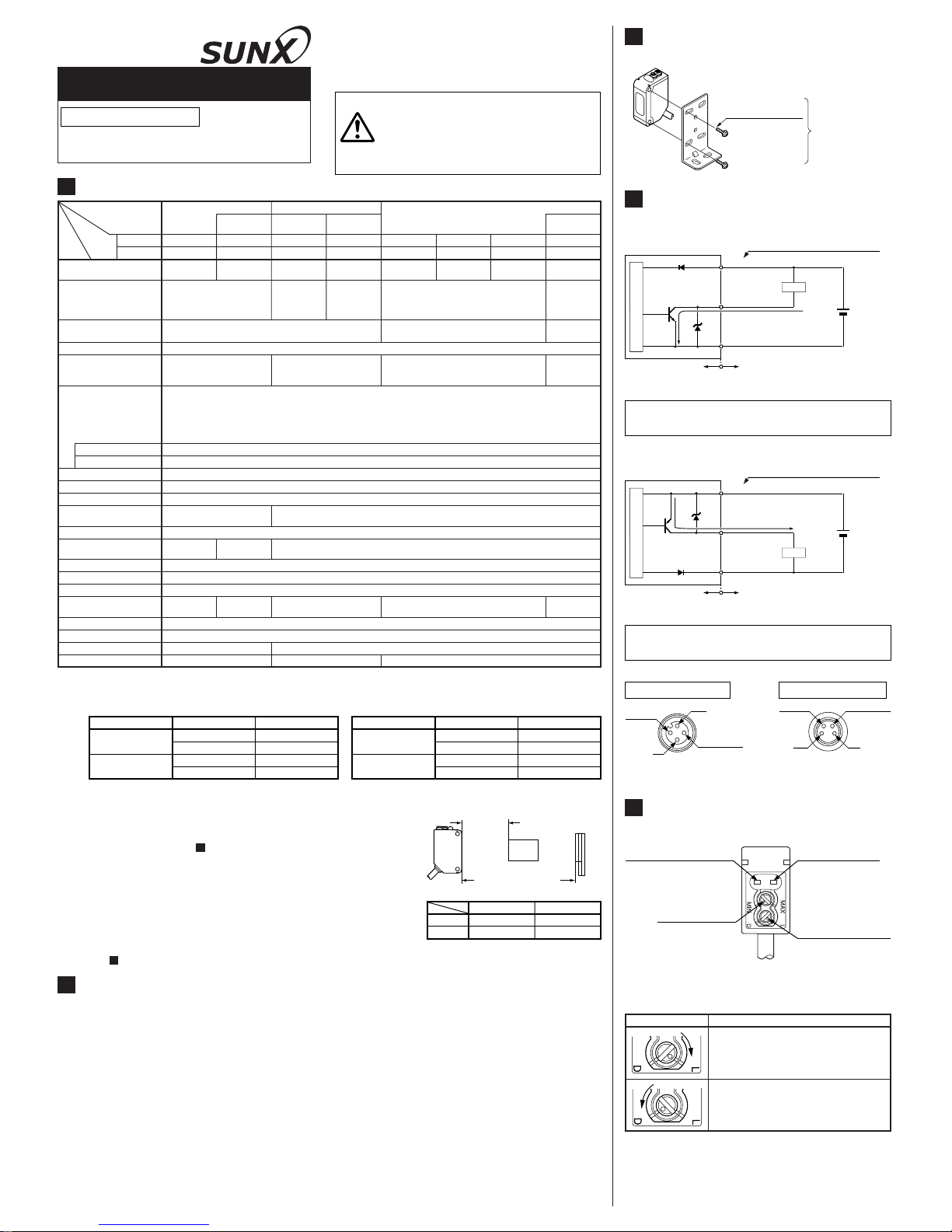
I/O CIRCUIT DIAGRAMS
4
٨ Connector pin position of the connector type
M12 pigtailed type
Not connected
2
Output (Note)
㧠
V
1
0V
3
M8 connector type
Not connected
2
Output (Note)
㧠
V
1
0V
3
Note: The thru-beam type sensor emitter does not incorporate the
output.
٨ NPN output type
D
T
r
ZD
+
-
12 to 24V DC
r10%
Internal circuit Users' circuit
Load
(Black / 4)
Output(Note)
(Blue / 3)0V
(Brown / 1) +V
Color code / Connector pin No. of
the connector type
100mA max.
Sensor circuit
Note: The thru-beam type sensor emitter does not incorporate the
output.
Symbols...D
Z
D
Tr
: Reverse supply polarity protection diode
: Surge absorption zener diode
: NPN output transistor
Note: The thru-beam type sensor emitter does not incorporate the
output.
٨ PNP output type
Internal circuit Users' circuit
Color code / Connector pin No. of
the connector type
D
T
r
ZD
+
-
12 to 24V DC
r10%
Load
(Black/4)
Output (Note)
(Blue / 3) 0V
(Brown / 1) +V
100mA max.
Sensor circuit
Symbols...D
Z
D
Tr
: Reverse supply polarity protection diode
: Surge absorption zener diode
: PNP output transistor
ADJUSTMENTS
5
٨ Operation mode switch
Operation mode switch
Description
Light-ON mode is obtained when the operation mode switch (located on the receiver) is
turned fully clockwise (L side).
Dark-ON mode is obtained when the operation mode switch (located on the receiver) is
turned fully counterclockwise (D side).
٨ Part description
Operation mode switch
(Note 1)
L: Light-ON
D: Dark-ON
Operation indicator
(Orange) (Note 2)
Lights up when the
sensing output is
ON
Sensitivity adjuster
(Note 1)
Sensing range becomes longer when
turned clockwise
Stability indicator (Green)
(Note 1)
Lights up under the stable
light condition or the stable
dark condition
Notes: 1)2)Not incorporated on the thru-beam type sensor emitter.
It is the power indicator (green: lights up when the power
is ON) for the thru-beam type sensor emitter.
SPECIFICATIONS
1
Automatic interference
prevention function
Long sensing range
70 to 200mm
(Note 4)
800mm
(Note 4)
15m
5m
(Note 3)
300mm
(Note 4)
10m
3m
(Note 3)
100mm
(Note 4)
Sensing range
Narrow-view
CX-422
CX-422-P
CX-423
CX-423-P
CX-412
CX-412-P
CX-491
CX-491-P
CX-493
CX-493-P
CX-424
CX-424-P
CX-421
CX-421-P
CX-411
PNP output
NPN output
Model No.
(Note 1)
CX-411-P
Item
With polarizing
filters (Note 2)
Long sensing range
RetroreflectiveThru-beam Diffuse reflective
Type
20mA or less
25mA or less
12 to 24V DCr10% Ripple P-P 10% or lessSupply voltage
20mA or lessCurrent consumption
Emitter: 20mA or less
(CX-412غ: 25mA or less)
Receiver: 20mA or less
1mmorless
0.5mm or less
0.5mm or less
Repeatability
(perpendicular to sensing axis)
Opaque,
translucent or
transparent
object (Note 5)
Ǿ50mm or
more opaque
or translucent
object (Note 3)
Ǿ12mm or more opaque
object
Ǿ50mm or more
opaque, translucent or specular
object (Note 3)
Opaque, translucent or transparent
object
Sensing object
Infrared LED
(modulated)
0.2mm
2
3-core (thru-beam type sensor emitter: 2-core) cabtyre cable, 2m longCable
Enclosure: PBT, Lens: Acrylic, Indicator cover: Acrylic
Red LED
(modulated)
Red LED
(modulated)
Red LED (modulated) Infrared LED (modulated)Emitting element
IP67 (IEC)Protection
-25to+55 (No dew condensation or icing allowed), Storage: -30 to +70Ambient temperature
35 to 85% RH, Storage: 35 to 85% RHAmbient humidity
Incorporated (Two units of sensors can be mounted closely.)
Continuously variable adjusterSensitivity adjuster
Green LED (lights up when the
power is ON), located on the emitter
Power indicator
Green LED (lights up under stable light received condition or stable dark condition), thru-beam type sensor: located on the receiver
Stability indicator
Orange LED (lights up when the output is ON), thru-beam type sensor: located on the receiverOperation indicator
1ms or less
㧙
㧙
㧙㧙
㧙
(Note 6)
Response time
Switchable either Light-ON or Dark-ON
Incorporated
Output
Output operation
Short-circuit protection
<NPN output type>
NPN open-collector transistor
Maximum sink current: 100mA
Applied voltage: 30V DC or less (between output and 0V)
Residual voltage: 1V or less (at 100mA sink current)
0.4V or less (at 16mA sink current)
<PNP output type>
PNP open-collector transistor
Maximum source current: 100mA
Applied voltage: 30V DC or less (between output and +V)
Residual voltage: 1V or less (at 100mA source current)
0.4V or less (at 16mA source current)
RF-230 (Reflector): 1 pc.
Material
50g approx.
Emitter: 45g approx., Receiver: 50g approx.
Weight
Accessory
Notes: 1) The model No. with suffix '-J' is the M12 pigtailed type, '-Z' is the M8 connector type.
(e.g.) M12 pigtailed type: CX-411-J, M8 connector type: CX-411-Z
Use the connection cables as shown below. (Two sets are required for the thru-beam type sensor.)
<Connection cable for the M12 pigtailed type>
Type Model No. Cable length
2-core type
CN-22-C2 2m
CN-22-C5 5m
4-core type
CN-24-C2 2m
CN-24-C5 5m
<Connection cable for the M8 connector type>
Type Model No. Cable length
Straight type
CN-24A-C2 2m
CN-24A-C5 5m
Elbow type
CN-24AL-C2 2m
CN-24AL-C5 5m
2)
3)
4)
5)
6)
The model No. with suffix 'E' shown on the label affixed to the thru-beam type sensor is the emitter, ' D' shown on the label is the receiver.
Thru-beam type sensor emitter: CX-41غE, Thru-beam type sensor receiver: CX-41غD
The model No. of retroreflective type sensor with the suffix '-Y' is the sensor without the RF-230 reflector.
(e.g.) CX-491-Y
The retroreflective type sensor with polarizing filters may not stably detect specular
or glossy objects through transparent film since light is polarized by the transparent
film. For details, refer to ' RETROREFLECTIVE TYPE SENSOR WITH POLAR-
IZING FILTERS'.
The sensing range and the sensing object of the retroreflective type sensor is specified
fot the RF-230 reflector. The sensing range represents the actual sensing range of the
sensor. The sensing ranges itemized in 'A' of the table below may vary depending of the
shape of sensing object. Be sure to check the operation with the actual sensing object.
The sensing range of the diffuse reflective type sensor is specified for white nonglossy paper (200 200mm) as the object.
The minimum sensing object of the diffuse reflectivenarrow-view type sensor is
Ǿ0.5mm copper wire.
By mounting interference prevention filters (PF-CX4-غ), two sets of the sensor can be mounted close together. For details, refer
to ' INTERFERENCE PREVENTION FILTER (OPTIONAL)'.
8
10
Sensing range
(A)
Reflector setting range
(B)
Sensor Reflector
Sensing
object
A
B
3m
0.1 to 3m5m0.1to5m
CX-491غ CX-493غ
MOUNTING
3
٨ The tightening torque should be 0.5N㨯m or less.
Sensor mounting
bracket
(Optional)
M3 (length 12mm)
screw with washers
Phone: 800.894.0412 - Fax: 888.723.4773 - Web: www.clrwtr.com - Email: info@clrwtr.com
RETROREFLECTIVE TYPE SENSOR WITH POLARIZING FILTERS
(CX-491š)
8
٨ As light is polarized by a transparent film or mem-
brane, CX-491غ may not detect an object covered
or wrapped by transparent film. In that case, take
the following measures.
<Example of sensing objects>
Can wrapped by clear film
Aluminum sheet covered by plastic film
Gold or silver color (glossy) labels or wrapping
paper
<Measures>
Tilt the sensor with respect to the sensing object
upon fitting.
Reduce the sensitivity.
Increase the distance between the sensor and the
sensing object.
How to mount
SLIT MASK (OPTIONAL)
(Exclusively for thru-beam type sensor)
9
٨ With the slit mask (OS-CX-غ), the sensor can
detect a small object.
However, the sensing range is reduced when
the slit mask is mounted.
ԘԙInsert the fixing hook into the fixing groove.
Then, pressing the slit mask against the main
unit, insert the fixing tab into the fixing groove.
ԘԙInsert a screwdriver into the removing tab.
Pull forward while lifting the removing tab.
How to remove
Type Model No. Slit size
Round slit mask
OS-CX-05 Ǿ0.5mm
OS-CX-1 Ǿ1mm
OS-CX-2 Ǿ2mm
Rectangular slit
mask
OS-CX-05g6 0.56mm
OS-CX-1g6 16mm
OS-CX-2g6 26mm
Fixing groove
Fixing tab
Removing tab
Slit mask
Fixing groove
Fixing hook
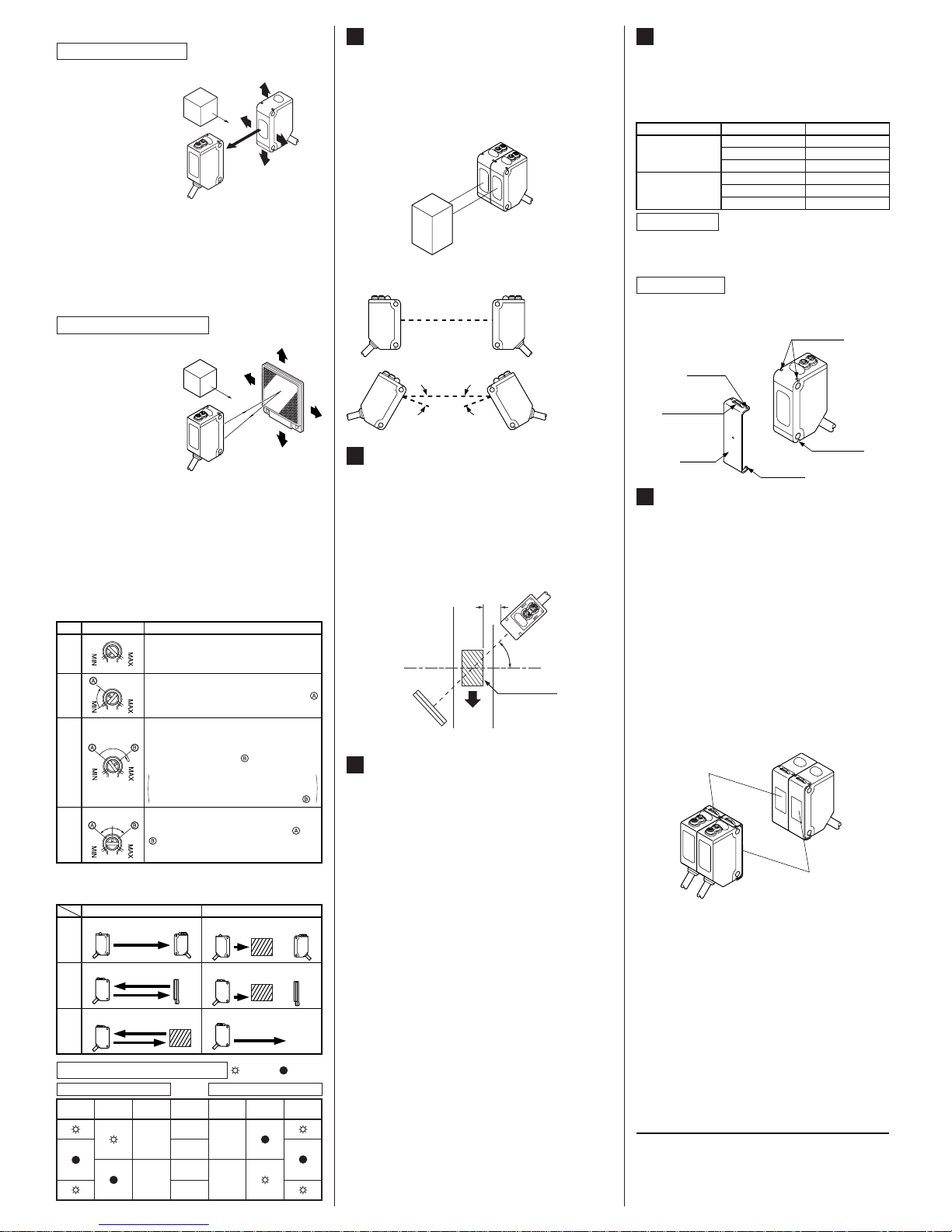
INTERFERENCE PREVENTION FILTER (OPTIONAL)
(Exclusively for CX-411š)
10
٨
٨
٨
By mounting the interference prevention filters
(PF-CX4-غ), two sets of the CX-411غ can be
mounted close together.
However, the sensing range is reduced when
the interference prevention filter is mounted.
The filters can be mounted by the same method
as for the slit masks.
Since there are two types of the interference
prevention filter, the two sets of sensors should
be fitted with different types of interference prevention filters, as shown in the figure below.
The interference prevention does not work even
if the filters are mounted for emitters only, receivers only or the same model No. of the interference prevention filters are mounted on both
the sets of the sensor.
Fitted with
PF-CX4-H
Fitted with
PF-CX4-V
٨ Sensitivity adjustment
Note: Use the 'minus' adjusting screwdriver (please arrange sepa-
rately) to turn the adjuster slowly. Turning with excessive
strength will cause damage to the adjuster.
Ԙ
ԙ
Ԛ
ԛ
Turn the sensitivity adjuster fully counterclockwise to the minimum sensitivity position, MIN.
In the light received condition, turn the sensitivity
adjuster slowly clockwise and confirm the point
where the sensor enters the 'Light' state operation.
In the dark condition, turn the sensitivity adjuster further clockwise until the sensor enters the 'Light' state operation and then bring
it back to confirm point where the sensor
just returns to the 'Dark' state operation.
If the sensor does not enter the 'Light' state
operation even when the sensitivity adjuster is
turned fully clockwise, the position is point .
The position at the middle of points and
is the optimum sensing position.
Step
Sensitivity adjuster
Description
Optimum position
Diffuse
reflective
Thru-beam
Retroreflective
Light received condition Dark condition
Emitter Receiver
Sensing
object
Sensor
Sensor Reflector
Emitter Receiver
Sensing
object
Sensor
Sensing
object
Sensor Reflector
Relation between output and indicators
In case of Light-ON In case of Dark-ON
: Lights up,
: Turns off
Stable light
receiving
Stable dark
receiving
Unstable light
receiving
Unstable dark
receiving
Stability
indicator
Operation
indicator
Output
ON OFF
OFF ON
Stability
indicator
Operation
indicator
Output
Sensing
condition
LONG SENSING RANGE RETROREFLECTIVE TYPE SENSOR
(CX-493š)
7
٨ Please take care of the following points when
detecting materials having a gloss.
ԘԙMake 'L', shown in the diagram, sufficiently
long.
Install at an angle of 10 to 30 degrees to the
sensing object.
* CX-491غ do not need the above adjustment.
L
10 to 30q
Sensing
object
Reflector
Glossy surface
SUNX Limited
٨ Beam alignment
Ԙ
ԙ
Ԛ
ԛ
Ԝ
ԝ
Set the operation mode switch to the Light-ON mode
position (L side).
Placing the emitter
and the receiver face
to face along a straight
line, move the emitter
in the up, down, left
and right directions, in
order to determine the
range of the light received condition with
the help of the operation indicator (orange).
Then, set
the emitter at the center of this range.
Similarly, adjust for up, down, left and right angular
movement of the emitter.
Further, perform the angular adjustment for the receiver also.
Check that the stability indicator (green) lights up.
Choose the operation mode, Light-ON or Dark-ON, as
per your requirement, with the operation mode switch.
Sensing object
Emitter
Receiver
Thru-beam type sensor
Ԙ
ԙ
Ԛ
ԛ
Ԝ
ԝ
Set the operation mode switch to the Light-ON mode
position (L side).
Placing the sensor
and the reflector
face to face along a
straight line, move
the reflector in the
up, down, left and
right directions, in
order to determine
the range of the
light received condition with the help of
the operation indicator (orange). Then, set the reflector at the center of this range.
Similarly, adjust for up, down, left and right angular
movement of the reflector.
Further, perform the angular adjustment for the
sensor also.
Check that the stability indicator (green) lights up.
Choose the operation mode, Light-ON or Dark-ON, as
per your requirement, with the operation mode switch.
Retroreflective type sensor
Reflector
Sensor
AUTOMATIC INTERFERENCE
PREVENTION FUNCTION
(Excluding thru-beam type sensor)
6
Note: If two diffuse reflective type sensor are mounted facing each
other, they should be angled so as not to receive the beam
from the opposing sensor or to detect its front face.
٨ Retroreflective type sensor and diffuse reflective
type sensor incorporate this function. Up to two
sets of sensor can be mounted closely.
(Thru-beam type sensor does not have this function.)
Close mounting of two sensors
No good
ǰ ǰ
Good
Phone: 800.894.0412 - Fax: 888.723.4773 - Web: www.clrwtr.com - Email: info@clrwtr.com
 Loading...