

Thank you very much for using SUNX products. Please read this Instruction Manual carefully and
thoroughly for the correct and optimum use of this product. Kindly keep this manual in a convenient
place for quick reference.
٨٨Never use this product as a sensing device for personnel protection.
In case of using sensing devices for personnel protection, use products which
meet standards, such as OSHA, ANSI or IEC etc., for personnel protection
applicable in each region or country.
WARNING
When detecting a specular object (aluminum
or copper foil, etc.) or an object having a
glossy surface or coating, please take care
that there are cases when the object may
not be detected due to a small change in
angle, wrinkles on the object surface, etc.
٨
MOUNTING
2
٨
The tightening torque should be 0.5N㨯m or less.
Sensor mounting bracket
MS-CX-3
(Optional)
M3 (length 12mm)
screw with washers
٨ Care must be taken regarding the sensor
mounting direction with respect to the
object's direction of movement.
Sensing
object
Sensing
object
Sensing object
Do not make the sensor
detect an object in this
direction because it may
cause unstable operation.
Notes: 1) The model No. with suffix '-Z'㩷is M8 plug-in connecotor type.
(Example)CX-441-P-Z
For the M8 plug-in connector type, use the following mating cables.
CN-24A-C2 (Straight type, 4-core, cable length 2m) CN-24AL-C2 (Elbow type, 4-core, cable length 2m)
CN-24A-C5 (Straight type, 4-core, cable length 5m) CN-24AL-C5 (Elbow type, 4-core, cable length 5m)
23.1mm
Ǿmm
Ǿ9mm
20.5mm
Ǿmm
Ǿ9mm
31.4mm
2)3)The adjustable range stands for the maximum sensing range which can be set with the distance adjuster.
The detection may be unstable depending on the mounting conditions or the sensing object to be used. In the
state that this product is mounted, be sure to check the operation with the actual sensing object to be used.
When a specular body is present below the
sensor, use the sensor by tiling it slightly
upwards to avoid wrong operation.
٨
Tilt
Specular
face
Specular
face
٨
٨
If a specular body is present in the
background, wrong operation may be
caused due to a small change in the angle
of the background body. In that case, install
the sensor at an inclination and confirm the
operation with the actual sensing object.
Take care that there is a non-detactable
area right in front of the sensor.
٨
٨
٨
٨
Make sure that the power supply is off while
wiring and adjusting.
Take care that wrong wiring will damage the
sensor.
Verify that the supply voltage variation is
within the rating.
If power is supplied from a commercial
switching regulator, ensure that the frame
ground (F.G.) terminal of the power supply
is connected to an actual ground.
CAUTIONS
3
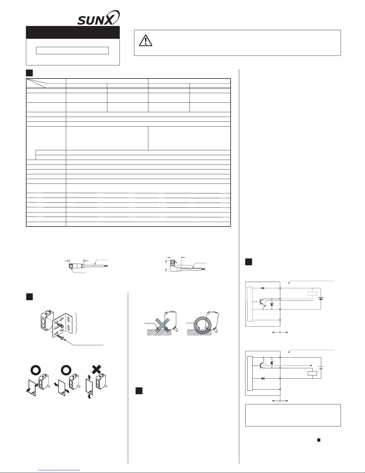
SPECIFICATIONS
1
Incorporated (Note 3)
Orange LED (lights up when the output is ON)
Green LED (lights up under stable operating condition)
5-turn mechanical adjuster
BGS/FGS function Switchable with wiring of sensing mode selection input
-20 to +55 (No dew condensation or icing allowed), Storage: -25 to +70
Enclosure: PBT, Front cover: Polycarbonate, Display cover: Polycarbonate
1ms or less
Incorporated
Operation indicator
Response time
Stability indicator
Distance adjuster
Sensing mode
Automatic interference
prevention function
2 to 50mm 20 to 300mm 2 to 50mm 20 to 300mm
Hysteresis
(with white non-glossy paper)
Type
Adjustable range (Note 2)
NPN output
PNP output
CX-442-PCX-441
20 to 50mm 40 to 300mm 20 to 50mm 40 to 300mm
CX-442 CX-441-P
Model No. (Note 1)
Item
2% or less of
operation distance
5% or less of
operation distance
2% or less of
operation distance
5% or less of
operation distance
Supply voltage
Repeatability
12 to 24V DCr10%ޓRipple P-P 10% or less
Along sensing axis: 1mm or less, Perpendicular to sensing axis: 0.2mm or less (with white non-glossy paper)
Output
Switchable either Detection-ON or Detection-OFF
Output operation
Short-circuit protection
NPN open-collector transistor
Maximum sink current: 100mA
Applied voltage: 30V DC or less (between output and 0V)
Residual voltage: 1V or less (at 100mA sink current)
ޓޓޓޓޓޓ
0.4V or less (at 16mA sink current)
PNP open-collector transistor
Maximum source current: 100mA
Applied voltage: 30V DC or less (between output and +V)
Residual voltage: 1V or less (at 100mA source current)
ޓޓޓޓޓޓ
0.4V or less (at 16mA source current)
25mA or less
Power consumption
Protection
55g approx.
Weight
IP67IEC
35 to 85% RH, Storage: 35 to 85% RH
Ambient temperature
Ambient humidity
Red LED (modulated)
Emitting element
0.2mm
2
4-core cabtyre cable, 2m long
Cable
Material
Sensing range
(with white non-glossy paper)
12 to 24V DC
r1
0%
D
1
Tr
1
(
Brown /
1
) 㧗V
(Black /
4)
Output
(Blue / 3) 0V
Z
D1
100mA max.
Color code/Connector pin No.
of the plug
-in connector type
Load
(Pink / 2
) Sensing mode selection input
(
Note)
Users' circuit
12 to 24V DC
r10%
(Pink / 2) Sensing mode selection input
(Note)
D2
(Brown / 1) 㧗V
(Black / 4)Output
(Blue / 3) 0V
Users' circuit
Z
D2
100mA max.
Color code/Connector pin No.
of the plug-in connector type
Tr2
Load
Note:
The sensing mode (BGS/FGS function) can be
selected by wiring of the sensing mode selection
input (pink / 2). For details, refer to ' BGS/FGS
FUNCTION'.
6
D1, D2
ZD1, ZD2
Tr1
Tr2
:
:
Reverse supply polarity protection diode
Surge absorption zener diode
NPN output transistor
PNP output transistor
:
:
٨
٨
٨
٨
٨
٨
٨
٨
٨
٨
٨
In case noise generating equipment
(switching regulator, inverter motor, etc.) is
used in the vicinity of this product, connect
the frame ground (F.G.) terminal of the
equipment to an actual ground.
Cable extension is possible up to total 100m
with 0.3mm
2
,
or more, cable. However, in
order to reduce noise, make the wiring as
short as possible.
Do not run the wires together with highvoltage lines or po
wer lines or put them in
the same raceway. This can ca
use
malfunction due to induction.
Take care that the sensor is not directly
exposed to fluorescent light from a rapid-starter
lamp or a high frequency lighting device, as it
may affect the
sensing performance.
Do not use during the initial transient time
(50ms) after the power supply is switched on.
This sensor is suitable for indoor use only.
A mechanical structure is employed for the
distance adjuster of this product. Take care
not to drop the product.
Do not use this sensor in places having excessive
vapor, dust, etc., or where it may come in direct
contact with water, or corrosive gas.
Take care that the sensor does not come in
direct contact with water, oil, grease, or
organic solvents, such as, thinner, etc.
This sensor cannot be used in an
environment containing inflammable or
explosive gases.
Never disassemble or modify the sensor.
4
I/O CIRCUIT DIAGRAMS
Internal circuit
NPN output type
٨
Sensor circuit
PNP output type
٨
Internal circuit
Sensor circuit
Symbols...
INSTRUCTION MANUAL
CX-44š
Compact Photoelectric sensor CX-400 series
Adjustable Range Reflective Type
٨
In the condition where the sensing
surface
of the sensor is facing right
ward, face the
' ' logo marked
on the connector to
the front and connect them. (Refer to the
figure below.)
'㩷㩷㩷㩷㩷㩷㩷㩷㩷㩷㩷㩷㩷㩷 '
logo
Connector arrangement of the
connection cable
for M8 plug-in
connector type
Sensing
surface
Connector pin
arrangement of
the sensor side
connector
M8 PLUG-IN CONNECTOR TYPE
10
٨
Before connecting the M8 plug-in connector
type (CX-44غ-Z) with the optional connection
cable for M8 plug-in connector type (CN-24A-C
غ
CN-24AL-Cغ), be sure to check the posi-
tion of the connector pins on the sensor
side connector and the connector of the
connection cable. If those are connected
improperly, the connector pins of the sensor may get damaged.
PRINTED IN JAPAN
Head Office
2431-1 Ushiyama-cho, Kasugai-shi, Aichi, 486-0901,
Japan
Phone: +81-(0)568-33-7211 FAX: +81-(0)568-33-2631
Overseas Sales Dept.
Phone: +81-(0)568-33-7861 FAX: +81-(0)568-33-8591
http://www.sunx.co.jp/
SUNX Limited
ޛIn case BGS function is usedޜޛIn case FGS function is used
ޜ
Brown
Black
Blue
Pink
+V
Ou
tput
0V
Brown
Black
Blue
Pink
+V
Output
0V
ޛBGS functionޜ
This function is used when the sensing object
is apart from the background.
ޛFGS function
ޜ
This function i
s used
when the sensing object
contacts the background
or the sensing object is
glossy, etc.
Sensing
object
Background
Sensing object
Background
OPERATION MODE SWITCH
7
Description
Detection-ON mode is obtained when
the switch is turned fully clockwise.
(L side)
Detection-OFF mode is obtained when
the switch is turned fully counterclockwise. (D side)
Operation
mode switch
Note:
Turn the distance adjuster gradually and lightly
with a screwdriver (please arrange separately).
If the operation mode switch is over turned or
pressed heavily, it may be damaged.
٨
Depends on a selection of either BGS or FGS
function, the output operation changes as follows.
Sensing range
Non-detectable
area
Adjusted distance
ON
OFF
ON
OFF
ON
OFF
ON
OFF
L-ON
D-ON
BGS
L-ON
D-ON
FGS
PART DESCRIPTION
5
Distance adjuster (5-turn)
Operation
mode switch
Operation indicator
(Orange)
Stability indicator (Green)
2
4
1
+V
3
0V
Output
Sensing mode
selection input
Connector pin position (M8 plug-in connector type)
٨
BGS/FGS FUNCTION
6
٨
This sensor incorporates BGS/FGS function.
Select either BGS or FGS function depending
on the positions of the background and sensing object. BGS/FGS function can be selected by wiring of the sensing mode selection
input (pink / 2), as shown in the figure below.
Note:
When this product is used, be sure to wire the
sensing mode selection input (pink / 2).
STABILITY INDICATOR
8
٨
Since the CX-44غ use a 2-segment
photodiode as its receiving element, and
sensing is done based on the difference in
the incident beam angle of the reflected
beam from the sensing object, the output
and the operation indicator (orange) operate
according to the object distance.
Further, the stability indicator (green) shows
the margin to the setting distance.
Setting distance
Sensing
object
Stable
operating
condition
Stable operating
condition
Unstable operating
condition
Output
(operation indicator)
(In case of Detection-ON)
Stability indicator
ON (lights up)
OFF (lights off)
Lights up
Lights off
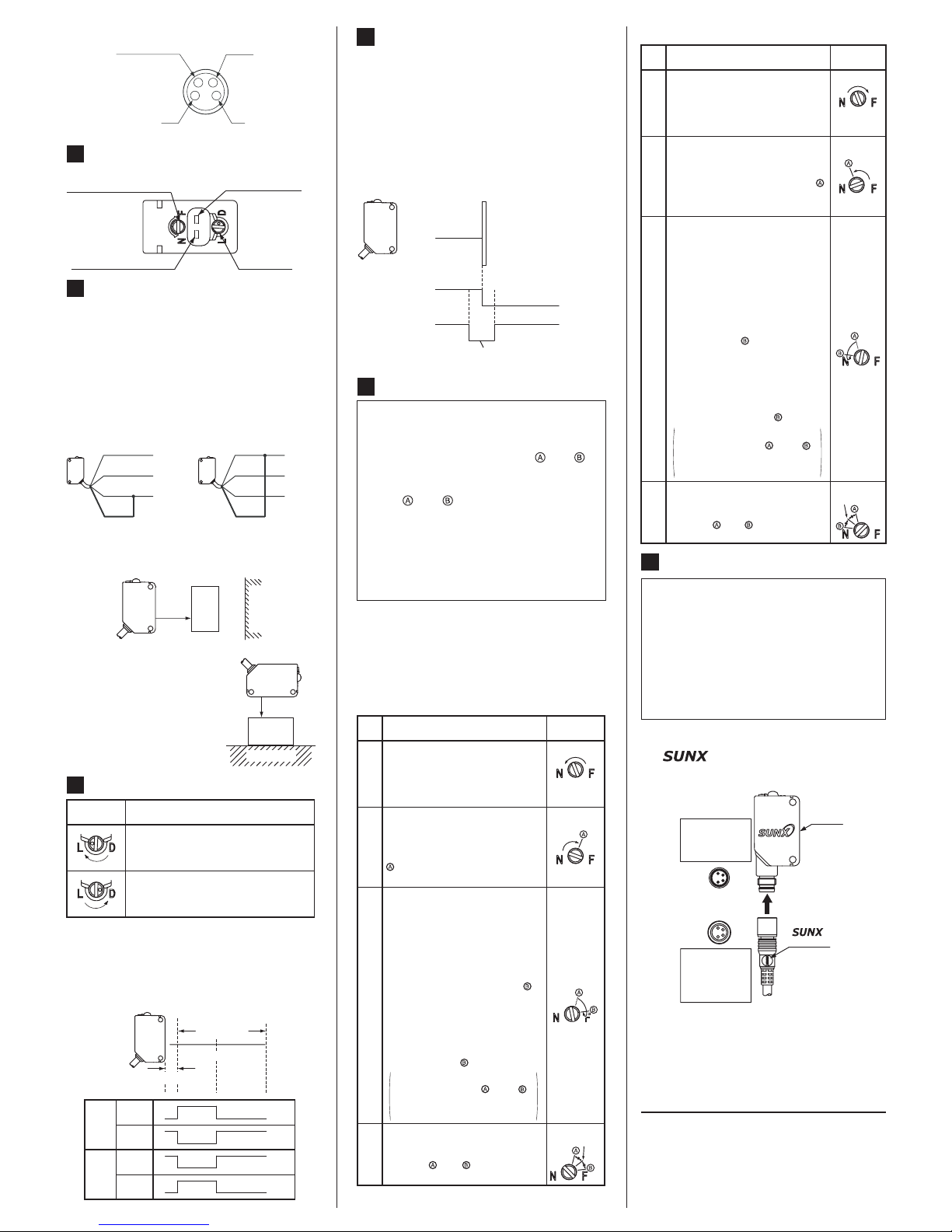
DISTANCE ADJUSTMENT
9
٨
Turn the distance adjuster gradually and lightly with a screwdriver (please arrange separately). In order to protect itself, the distance
adjuster idles if turned fully.
If the adjuster is idled when distance adjustment is done, carry out the adjustment again.
٨
٨
٨
When this product is used, be sure to carry
out the distance adjustment.
Since the distance adjuster of this sensor is a
5-turn adjuster, when the point and is
adjusted as explained in the table below,
there may be more than 1 turn between the
point and .
Therefore, make sure to remember the turns
of both points to find the optimum position.
Be sure to wire the sensing mode selection
input (Pink/2) before distance adjustment. If
the wiring is done after the distance
adjustment, the sensing area is changed.
Turn fully
Ԙ
ԙ
Ԛ
Description
Turn the distance adjuster fully
counterclockwise to the minimum
sensing range position.
(40mm ap-
prox., 20mm approx. for CX-441غ
Distance
adjuster
Step
Place an object at the required
distance from the sensor, turn the
distance adjuster gradually
clockwise, and find out point
where the sensor changes to
the detecting condition.
Remove the object, turn the adjuster clockwise further until the
sensor goes into the detecting
state again. Once it has entered,
turn the adjuster backward a little until the sensor returns to the
undetecting condition. That
posi-
tion is designated as point
.
When the sensor does not go into the detecting condition even if
the adjuster is fully turned clockwise, the position where the adjuster was fully turned is regarded as the point .
ԛ
The optimum position to stably
detect objects is the center point
between and .
Optimum
position
There may be more than 1 turn
between the point and ,
since this sensor incorporates
5-turn adjuster.
٨ In case BGS functin is used.
٨
In case FGS functin is used.
Ԙ
ԙ
Ԛ
Description
Turn the distance adjuster fully
clockwise to the maximum sensing range position.
(300mm ap-
prox., 50mm approx. for CX-441غ
Distance
adjuster
Step
In the state where the sensor detects the background, turn the
distance adjuster gradually counterclockwise, and find out point
where the sensor changes to the
undetecting condition.
Turn fully
Optimum
position
ԛ
The optimum position to stably
detect objects is the center point
between and .
There may be more than 1 turn
between the point and ,
since this sensor incorporates
5-turn adjuster.
Place an object at the required distance from the sensor
, turn the
adjuster counterclockwise further until the sensor goes into
the undetecting condition again.
Once it has entered, turn the adjuster backward a little until the
sensor returns to the detecting
condition.That position is designated as point . When the sensor does not go into the undetecting condition even if the
adjuster is fully turned counterclockwise, the position where
the adjuster was fully turned is
regarded as the point .
 Loading...